Assembly: Basic Assembly Access
This section describes the Creo TOOLKIT functions that access the contents of a Creo Parametric assembly. Before you read this section, you should be familiar with the following documentation:
•  User Interface: Selection
•  Core: Coordinate Systems and Transformations
•  Core: 3D Geometry
Structure of Assemblies and Assembly Objects
The object ProAssembly is an instance of ProSolid and shares the same declaration. The ProAssembly object can therefore be used as input to any of the ProSolid and ProMdl functions applicable to assemblies. In particular, because you can use the function ProSolidFeatVisit() to traverse features, you can extract the assembly datum features and their geometry in the same way as for parts (described in detail in the section on Core: 3D Geometry).
However, assemblies do not contain active geometry items other than those in datums—that is, no “solid” geometry as described in the Core: 3D Geometry and Element Trees: Principles of Feature Creation sections. Therefore, the function ProSolidBodySurfaceVisit() will not find any surfaces, and solid assembly features such as holes and slots will not contain active surfaces or edges.
The solid geometry of an assembly is contained entirely in its components. Each component is a feature of type PRO_FEAT_COMPONENT, which is a reference to a part or another assembly, plus a set of parametric constraints for determining its geometric location within the parent assembly.
Assembly features that are solid, such as holes and slots, and therefore affect the solid geometry of parts in the assembly hierarchy, do not themselves contain the geometry items that describe those modifications. These items are always contained in the parts whose geometry is modified, within local features created for that purpose of type PRO_FEAT_ASSEM_CUT.
The most important Creo TOOLKIT functions for assemblies are those that operate on the components of an assembly. The object ProAsmcomp, which is an instance of ProFeature and shares its DHandle declaration, is defined for that purpose. Each assembly component is treated as a variety of feature, and the integer identifier of the component is also the feature identifier.
An assembly component can be another assembly. In general, therefore, an assembly can contain a hierarchy of assemblies and parts at many levels, in which some assemblies and parts may appear more than once. To identify the role of any database item in the context of the root assembly, it is not enough to have the integer identifier of the item and the handle to its owning part or assembly, as would be provided by its ProFeature or ProGeomitem description. It is also necessary to give the full path of the assembly-component references down from the root assembly to the part or assembly that owns the database item. The object ProAsmcomppath, which is used as the input to Creo TOOLKIT assembly functions, accomplishes this purpose.
The declaration of ProAsmcomppath is as follows:
     typedef struct pro_comp_path
     {
       ProSolid    owner;
       ProIdTable  comp_id_table;
       int         table_num;
     } ProAsmcomppath;
The data structure fields are as follows:
•  owner—Identifies the root assembly
•  comp_id_table (the component identifier table)—An integer array that contains the identifiers of the components that form the path from the root assembly down to the component part or assembly being referred to
•  table_num—Specifies the number of component identifiers in the comp_id_table array
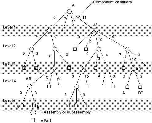
The following figure Sample Assembly Hierarchy shows an assembly hierarchy with two examples of the contents of a ProAsmcomppath object.
Sample Assembly Hierarchy
Image
In the assembly shown in Figure 12-1, Sample Assembly Hierarchy subassembly C is component identifier 11 within assembly A, Part B is component identifier 3 within assembly AB, and s on. The subassembly AB occurs twice. To refer to the two occurrnces of part B, use the following:
Component BComponent B"
table_num = 5          table_num = 4
comp_id_tab[0] = 2     comp_id_tab[0] = 11
comp_id_tab[1] = 2     comp_id_tab[1] = 6
comp_id_tab[2] = 5     comp_id_tab[2] = 12
comp_id_tab[3] = 2     comp_id_tab[3] = 3
comp_id_tab[4] = 3
A ProAsmcomppath structure in which table_num is set to 1 contains the same information as a ProAsmcomp object.
The object ProAsmcomppath is one of the main ingredients in the ProSelection object, as described in The Selection Object.
Visiting Assembly Components
Functions Introduced:
Each component of an assembly is also a feature of that assembly. Therefore, to visit the components, visit the features using ProSolidFeatVisit() and find those features whose type is PRO_FEAT_COMPONENT using the function ProFeatureTypeGet(). You can convert the ProFeature object for each component to the ProAsmcomp object by casting.
Properties Related to Component Purpose
Functions Introduced:
To create a ProAsmcomppath object for the component, use the function ProAsmcomppathInit() and set the component identifier table to contain only a single component identifier.
The function ProAsmcompMdlMdlnameGet() retrieves the model name and type for the component. If an assembly component is missing on retrieval, the function ProAsmcompMdlMdlnameGet() still provides information about the component while the function ProAsmcompMdlGet() fails to retrieve a valid model handle.
The function ProAsmcompMdlGet() provides the ProMdl handle to the part or assembly being referenced by the component. To traverse the components at all levels in the assembly hierarchy, make a recursive function to perform these steps:
1. Call ProAsmcompMdlGet() for each component of the root assembly to find the model for the component.
2. Call ProMdlTypeGet() to find out if the model is a part or an assembly.
3. If the model is an assembly, traverse each component by calling ProSolidFeatVisit() again.
The function ProAsmcomppathMdlGet() retrieves a model specified by ProAsmcomppath and is useful when analyzing a ProSelection object that refers to an assembly.
The function ProAsmcompTypeGet() yields the type of the assembly component. Examples of the possible types are as follows:
•  PRO_ASM_COMP_TYPE_WORKPIECE—Workpiece
•  PRO_ASM_COMP_TYPE_REF_MODEL—Reference model
•  PRO_ASM_COMP_TYPE_FIXTURE—Fixture
•  PRO_ASM_COMP_TYPE_MOLD_BASE—Mold base
•  PRO_ASM_COMP_TYPE_MOLD_COMP—Mold component
•  PRO_ASM_COMP_TYPE_MOLD_ASSEM—Mold assembly
•  PRO_ASM_COMP_TYPE_GEN_ASSEM—General assembly
•  PRO_ASM_COMP_TYPE_CAST_ASSEM—Cast assembly
•  PRO_ASM_COMP_TYPE_DIE_BLOCK—Die block
•  PRO_ASM_COMP_TYPE_DIE_COMP—Die component
•  PRO_ASM_COMP_TYPE_SAND_CORE—Sand core
•  PRO_ASM_COMP_TYPE_CAST_RESULT—Cast result
•  PRO_ASM_COMP_TYPE_FROM_MOTION—Component for use by Creo Simulate.
•  PRO_ASM_COMP_TYPE_NO_DEF_ASSUM—Component for which Creo Parametric cannot apply default assumptions.
The function ProAsmcompMdldataGet() takes the handle to the assembly component as its input argument and retrieves the following information:
•  r_mdl_type—Specifies the type of the model using the enumerated data type ProMdlType.
•  r_mdl_filetype—Specifies the file type of the component using the enumerated data type ProMdlfileType.
•  r_mdl_name—Specifies the name of the component. You must free this argument using the function ProWstringFree().
Component Placement
The function ProAsmcompIsBulkitem() reports whether an assembly component is a bulk item. A bulk item is a non-geometric assembly feature that should appear in an assembly bill of materials.
Use the function ProAsmcompIsPackaged() to determine whether the specified component is packaged.
Simplified Representations
The function ProAsmcompIsUnderconstrained() determines whether the specified component is underconstrained, that is, it has one or more constraints but they are not sufficient to fully constraint the component location.
The function ProAsmcompIsFrozen() determines whether the specified component is frozen. The frozen component behaves similar to the packaged component and does not follow the constraints that you specify.
From Creo Parametric 3.0 onward, the frozen status in components is set only during the regeneration of the model. You cannot use the freeze commands in the Creo Parametric user interface, to set the frozen status on a component. By default, behavior of the configuration option freeze_failed_assy_comp is ignored. For the models created in releases prior to Creo Parametric 3.0, the frozen status of components is retained during model retrieval.
The configuration option allow_freeze_failed_assy_comp allows you to restore the behavior of the configuration option freeze_failed_assy_comp and freeze commands in the Creo Parametric user interface. The valid values are:
•  yes—Specifies that the behavior of the configuration option freeze_failed_assy_comp is available. The freeze commands in the Creo Parametric user interface are also available. The valid values for the configuration option freeze_failed_assy_comp are:
  yes—Automatically freezes any component that fails retrieval into the assembly at its last known location.
  no—Requires you to perform specific actions to fix the assembly or freeze the component that fails retrieval.
•  no—This is the default value. Specifies that the behavior of the configuration option freeze_failed_assy_comp is ignored.
The functions ProAsmcompIsUnplaced() and ProAsmcompIsPlaced() determine whether the specified component is unplaced or placed respectively. Unplaced components belong to an assembly without being assembled or packaged.
The function ProAsmcompIsSubstitute() determines whether the specified component is substituted. When you substitute a component in a simplified representation, you temporarily exclude the substituted component and superimpose the substituting component in its place.
The function ProAsmcompVisibilityGet() to skip components of the master representation that are not shown in the representation when you traverse the assembly components of a simplified representation.
Modifying Component Properties
The function ProAsmcompTypeSet() enables you to set the type of a component.
The function ProAsmcompFillFromMdl() copies the template model into the model of the component.
Note
The function returns the error PRO_TK_UNSUPPORTED when the model to which the template model is being copied is an unsupported model. For example, it is an embedded model.
Use the function ProAsmcompMakeUniqueSubasm() to create a unique instance of a sub-assembly by specifying the path of the sub-assembly. The function ProAsmcompRmvUniqueSubasm() removes the instance of the sub-assembly.
The function ProAsmcompSetPlaced() forces Creo Parametric to consider a particular component to be placed or unplaced.
Example 1: Listing the Members of an Assembly
The sample code in the file UgAsmCompVisit.c located at <creo_toolkit_loadpoint>/protk_appls/pt_userguide/ptu_asmt, recursively lists the components of an assembly and writes the name of the solid for each component.
Locations of Assembly Components
Functions Introduced:
The function ProAsmcomppathTrfGet() provides the transformation matrix that describes the coordinate transformation between the coordinate system of an assembly component and that of the root assembly. As its name implies, its input is a ProAsmcomppath object, so it can be applied to a component at any level within an assembly hierarchy. It has an option to provide the transformation from bottom to top, or from top to bottom. (To apply the transformation, use the function ProPntTrfEval() or ProVectorTrfEval(), described in the section Coordinate Systems.)
In effect, this function describes the current position and orientation of the assembly component in the root assembly.
Use the function ProAsmpathProarrayFree() to free the memory allocated to the ProArray of type ProAsmpath.
Example 2: Finding the Position of a Component
The sample code in the file UgAsmcompTransfGet.c located at <creo_toolkit_loadpoint>/protk_appls/pt_userguide/ptu_asm shows a function that finds the matrix that describes the position of an assembly component in its parent assembly.
Assembling Components
To assemble components into an assembly, use the methods of feature creation. These methods are described in detail in section Assembly: Assembling Components.
Redefining and Rerouting Components
The functions used to redefine and reroute components are described in the section Assembly: Assembling Components.
Deleting Components
Function Introduced:
The function ProFeatureDelete() deletes components. It has the same options as described in the sectionchapter Core: Features.
Flexible Components
A flexible component allows variance of items such as features, dimensions, annotations, and parameters of a model in the context of an assembly.
The object ProAsmitem describes the contents of a variant item in an assembly component. The declaration for this object is as follows:
typedef struct pro_asm_item 
{
   ProModelitem item;
   ProName      name; /* used for PRO_PARAMETER in 
                         this case item->type == PRO_PART or PRO_ASSEMBLY */
   ProAsmcomppath path;
}  ProAsmitem;
Refer to the section Exploded State Objects for the declaration of the ProModelitem object. The field name in the ProAsmitem object is used only in case of PRO_PARAMETER; wherein the field type in the ProModelitem object is either PRO_PART or PRO_ASSEMBLY.
In case of parameter initialization, the field name specifies the parameter name and the fields type and id in the ProModelitem object initiate the model on which the parameter is defined. For non-parameter items such as features, dimensions, and annotations, the fields owner, type and id in the ProModelitem object have the same values as the values of the input arguments for the function ProModelitemInit().
The field path specifies the path from the top-level component model. This field is empty if the variant items are defined on the top-level component model.
Functions Introduced:
Use the function ProAsmcompAsmitemInit() to initialize the ProAsmitem object that describes the contents of a variant item in an assembly component.
The function ProAsmcompFlexibleSet() converts a specified assembly component to a flexible component based on an array of specified variant items.
Use the function ProAsmcompFlexibleUnset() to convert a flexible assembly component to a regular component.
Use the function ProAsmcompIsFlexible() to identify if the specified assembly component is a flexible component. The function returns PRO_B_TRUE if the component is a flexible component, otherwise it returns PRO_B_FALSE.
The function ProAsmcompFlexiblemodelAdd() creates a flexible model from the specified model of the flexible component.
Note
The model is temporarily converted into a flexible model in order to allow you to define variant items on it using the existing Creo TOOLKIT functions for variant items. If no variant items are added, the temporary flexible model becomes a regular one upon regeneration. You can convert a model into a temporary flexible model only via Creo TOOLKIT. For information on the functions that can be used to access and modify the variant items in a flexible assembly component, refer to the section Inheritance Feature and Flexible Component Variant Items.
The function ProAsmcompVarieditemsToModelAdd() adds an array of specified variant items to the predefined flexibility definition of the specified component model. All varied items are replaced by the provided ones.
The function ProAsmcompFlexibleWithPredefineditemsSet() converts a specified assembly component to a flexible component using the predefined flexibility definition of the variant items in the component model.
Embedded Components and Inseparable Assemblies
An embedded component is a copy of the component model that becomes a part of its parent assembly. The parent assembly can be the top-level assembly or a subassembly.
In an inseparable assembly some components are embedded in the assembly. It is a single file that contains the embedded components in the assembly. The assembly structure is visible in the Model Tree.
The inseparable assembly is created in the open session of Creo Parametric and must be saved to be used again. When you embed a component in an assembly, you copy the model to the assembly file. The original model is not affected and continues to exist in your database. The new embedded copy is not dependent on the original model. If you no longer need the original model, you can erase it from the session and remove it from the database. When you embed a component, the name of the embedded copy is appended to include the name of the owner assembly.
Functions Introduced:
Use the function ProAsmcompEmbed() to embed selected components in its owner assembly. The input arguments follow:
•  comp_sel—Selection of components specified using the array of ProSelection object.
•  embed_recursivelyProBoolean that is used only when the input argument comp_sel is a subassembly selection.
  If the value of embed_recursively is set to PRO_B_FALSE and comp_sel is a subassembly selection, only the subassembly is embedded.
  If the value of embed_recursively is set to PRO_B_TRUE and comp_sel is a subassembly selection, the subassembly and all the possible components are embedded.
The function ProAsmcompExtract() extracts the embedded component from the owner assembly. The input argument follow:
•  comp_sel—Selection of components specified using the array of ProSelection object.
•  newMdlName—Name of the new model.
The extracted component becomes a standalone model and replaces the embedded component in the assembly. This name of the new model is specified using the input argument newMdlName.
The function returns the error PRO_TK_NO_CHANGE if the selected component is not embedded in the owner assembly.
The function ProAsmcompEmbeddedOwnerMdlGet() returns the handle of the nonembedded owner model for the specified embedded model.
Refer to the Creo Parametric online help, for more information about Inseparable Assemblies and Embedded Components.
Exploded Assemblies
An exploded view of an assembly shows each component of the model separated from the other components. An exploded view affects the appearance of the assembly only. The design intent and the true distance between the assembly components do not change.
Functions Introduced:
The functions ProAssemblyExplode() and ProAssemblyUnexplode() enable you to explode and unexplode an assembly. The function ProAssemblyIsExploded() identifies whether the specified assembly is exploded. Use this function in the assembly mode only.
The exploded status of an assembly depends on the mode. If an assembly is opened in the drawing mode, the state of the assembly in the drawing view is displayed. The drawing view does not represent the actual exploded state of the assembly. Use the function ProDrawingViewExplodedGet() to get the exploded state of an assembly for a specified drawing view.
Note
These functions explode the assembly using the default exploded state of the assembly. Creo Parametric defines the positions of an assembly component in the default exploded state.
Exploded State Objects
The structure ProExpldstate describes the contents of an exploded state object. This object uses the same declaration as the ProModelitem, ProGeomitem, and ProFeature objects, which is as follows:
typedef struct pro_model_item
{
  ProType  type;
  int      id;
  ProMdl   owner;
} ProExpldstate;
Visiting Exploded States
Function Introduced:
The function ProSolidExpldstateVisit() enables you to visit all the exploded states in the specified solid, except for the default exploded state. For a detailed explanation of visiting functions, see the section Visit Functions in the Fundamentals section.
Accessing Exploded States
Functions Introduced:
The function ProExpldstateInit() returns the handle to a specified exploded state representation of a solid. It takes the following input arguments:
•  expld_name—Specifies the name of the exploded state. If you specify this value, then the function ignores the next argument expld_id.
•  expld_id—Specifies the identifier of the exploded state. This argument is applicable only if the argument expld_name is NULL.
•  p_solid—Specifies the Creo Parametric solid that contains the exploded state. This argument cannot be NULL.
The function ProExpldstateActivate() activates a specified exploded state representation of a solid.
The function ProExpldstateSelect() enables you to select a specific exploded state from the list of defined exploded states.
The function ProExpldstateActiveGet() retrieves the current active exploded state for the specified solid.
The functions ProExpldstateNameGet() and ProExpldstateNameSet() return and set, respectively, the name of the exploded state.
The function ProExpldstateExplodedcomponentsGet() returns an array of assembly component paths that are included in the exploded state.
The function ProExpldStateExplodeLinesGet() returns an array of explode lines for the specified exploded state.
The functions ProExpldstateMovesGet() and ProExpldstateMovesSet() retrieve and assign, respectively, the array of moves of an exploded state.
In order to define an exploded position of an assembly component (or a set of assembly components), you need to perform a sequence of moves. For example, you can move the assembly component over the X-axis, rotate over a selected edge, and then move over the Y-axis. In this case, the final position of the assembly component (or a set of assembly components) is attained by three moves.
The ProExpldAnimMoveData object describes the moves of an exploded state. The fields in this object are as follows:
•  comp_set—Specifies an array of paths of the assembly components, in the form of the ProAsmcomppath objects.
•  move—Specifies the move of the exploded state. It is given by the ProExpldAnimMove object. This object contains the following fields:
  move_type—Specifies the move type in terms of the enumerated type ProExpldAnimMoveType. The move can be one of the following types:
  PRO_EXPLDANIM_MOVE_TRANSLATE
  PRO_EXPLDANIM_MOVE_ROTATE
  direction—Depending upon the selected move type, this field specifies the translation direction or the rotational axis.
  value—Depending upon the selected move type, this field specifies the translational distance or the rotation angle.
The function ProExpldAnimDataTranslatemoveInit() creates a translational move based on the specified direction of the translation and the specified array of the assembly components to which this move is applied.
The function ProExpldAnimDataRotatemoveInit() creates a rotational move based on the specified rotational axis, rotation angle, and the specified array of the assembly components to which this move is applied.
The function ProExpldanimmovedataProarrayFree() clears the array of assigned ProExpldAnimMoveData objects.
Manipulating Exploded States
Functions Introduced:
The function ProExpldstateCreate() creates a new exploded state based on the values of the following input arguments:
•  p_solid—Specifies the assembly in which the exploded state is created. This argument cannot be NULL.
•  name—Specifies the name of the exploded state. This argument also cannot be NULL.
•  p_move_arr—Specifies an array of ProExpldAnimMoveData objects.
Use the function ProExpldstateDelete() to delete a specified exploded state.
Merge and Cutout
The Merge and Cutout function has been deprecated. Use the Merge feature element tree to create merge or cutout feature. See the section Merge Feature in Element Trees: Edit Menu Features for more details.
Automatic Interchange
Functions Introduced:
In Creo Parametric, it is possible to interchange an assembly component with another model that contains equivalent assembly constraints. The Creo TOOLKIT function that performs this action is ProAssemblyAutointerchange(). Depending on the type of component interchange, the assembly constraints may need to be respecified for the replacement model.
Instances in a family table share the same assembly constraints. Consequently, you can automatically replace an assembly component with another instance in the component's family table without respecifying any assembly constraints. Simply retrieve the handle for the replacement instance and pass this handle to ProAssemblyAutointerchange().
If the assembly component and replacement model are not instances in the same family table, you can define the necessary relationships between them interactively and save them in an Interchange Assembly. (See the Assembly Modeling User’s Guide for details.) To perform an interchange using models in an interchange assembly, first retrieve the interchange assembly (using the function ProMdlnameRetrieve()), and then pass the handle of the replacement model to function ProAssemblyAutointerchange(). Note that the interchange assembly must be in memory before the call to ProAssemblyAutointerchange().
An interchange assembly is not the same as an interchange domain. Interchange domains (.int files) contain interchange information, but they can no longer be created using Creo Parametric. However, it is possible to use ProAssemblyAutointerchange() to interchange models using an existing interchange domain.