Coordinate System Transformations
Functions Introduced:
All coordinate systems are treated in Creo TOOLKIT as if they were three-dimensional. Therefore, a point in any of the coordinate systems described is always represented in
C by the following type:
typedef double ProPoint3d[3]Vectors are distinguished for clarity by a different, though equivalent, declaration:
typedef double ProVector[3], Screen, window and section coordinates contain a Z value whose positive direction is normal to the screen or the sketch.
The value of Z is not generally important when specifying a screen location as an input to a function, but it is useful in
other situations. For example, if the user selects a datum plane, you can find out which side is towards the user by calculating
the normal to the plane, transforming to screen coordinates, then looking at the sign of the Z coordinate.
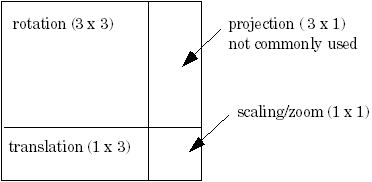
A transformation between two coordinate systems is represented by a 4x4 matrix, with the following type:
typedef double ProMatrix[4][4];This combines the conventional 3x3 matrix that describes the relative orientation of the two systems, and the vector that
describes the shift between them.
Transformation Matrix

Creo TOOLKIT provides two utilities for performing coordinate transformations. The function ProPntTrfEval() transforms a three-dimensional point, and ProVectorTrfEval() transforms a three-dimensional vector.
The source code for other utilities that manipulate transformation matrices is located in the file Matrix.c located at <creo_toolkit_loadpoint>/protk_appls/pt_examples/pt_utils/Util.
The following sections describe the functions needed to obtain the transformation matrix between two different coordinate
systems in Creo Parametric.
Transforming Solid to Screen Coordinates
Functions Introduced:
The view matrix describes the transformation from solid to screen coordinates. The function ProViewMatrixGet() provides the view matrix for the specified view. Example 1: Solid Coordinates to Screen Coordinates shows a function that transforms a point, using theProViewMatrixGet() function, and an example user function.
The function ProViewMatrixSet() changes the orientation of the solid model on the screen.
Example 1: Solid Coordinates to Screen Coordinates
The sample code in the file UgFundSolid2Screen.c located at <creo_toolkit_loadpoint>/protk_appls/pt_userguide/ptu_fundament shows how to transform solid coordinates to screen coordinates.
Example 2: Transform from Solid Coordinates to Screen Coordinates
The sample code in the file UgFundCsysTrf.c located at <creo_toolkit_loadpoint>/protk_appls/pt_userguide/ptu_fundament shows how to extract a selected point from the surface of a solid model, transform it from solid coordinates to screen coordinates,
write the results into a file and display it.
Transforming Screen to Window Coordinates
Functions Introduced:
Transformation from screen to window coordinates consists solely of a zoom factor and pan in X and Y.
The function ProWindowCurrentMatrixGet() gets the transformation matrix for the window. A pan and zoom transformation matrix consists of:
| • | The scale factor, running down the diagonal of the matrix. For example, to zoom in by a factor of 2, the value 2.0 will be down the diagonal in the elements (0,0), (1,1), and (2,2). |
| • | The translation factor (pan) in the elements (3,0) - X and (3,1) - Y. |
| • | The element at (3,3) should be 1.0. |
The function ProWindowPanZoomMatrixSet() can change the pan and zoom of the window. The matrix should contain only the elements listed above, for function ProWindowCurrentMatrixGet().
Transforming from Drawing View to Screen Coordinates in a Drawing
Function Introduced:
The function ProDrawingViewTransformGet() performs the transformation from drawing view coordinates (solid) to screen coordinates. It describes where a particular
point on the solid will be in the drawing for a particular view of the solid.
Transforming from Screen to Drawing Coordinates in a Drawing
Function Introduced:
The function ProDrawingSheetTrfGet() returns the matrix that transforms screen coordinates to drawing coordinates. The function performs this transformation for
the first sheet.
Example 3: Screen Coordinates to Drawing Coordinates
The sample code in the file UgFundScreen2Drw.c located at <creo_toolkit_loadpoint>/protk_appls/pt_userguide/ptu_fundament allows you to transform the screen coordinates to drawing coordinates.
Example 4: Transform from Screen Coordinates to Drawing Coordinates
The sample code in the file UgFundCsysTrf.c located at <creo_toolkit_loadpoint>/protk_appls/pt_userguide/ptu_fundament allows you to select a point from the screen, transform it from screen coordinates to drawing coordinates, write the results
into a file and display it.
Transforming Coordinates of an Assembly Member
Function Introduced:
The function ProAsmcomppathTrfGet() provides the matrix for transforming from the solid coordinate system of the assembly member to the solid coordinates of
the parent assembly, or the reverse.
Transforming to Coordinate System Datum Coordinates
Functions Introduced:
The function ProCsysDataGet() provides the location and orientation of the coordinate system datum in the solid coordinate system of the solid that contains
it. The location is in terms of the directions of the three axes, and the position of the origin. When these four vectors
are made into a transformation matrix using the function ProMatrixInit(), that matrix defines the transformation of a point described relative to the coordinate system datum back to solid coordinates.
To transform the other way, which is the more usual requirement, you need to invert the matrix. The example function ProUtilMatrixInvert(), inverts the specified matrix.
Transforming Coordinates of Sketched Entities
Function Introduced:
The function ProSectionLocationGet() provides the matrix for transforming from the solid coordinate system to the sketch coordinate system, or the reverse.
Example 5: Using Several Coordinate Transforms
The sample code in the file UgGraphZoomAtPoint.c located at <creo_toolkit_loadpoint>/protk_appls/pt_userguide/ptu_graphics demonstrates how to use several coordinate transformations. The function will zoom in on a solid model, with the results
centered at the selected location.