The Element Tree for an Assembly Component
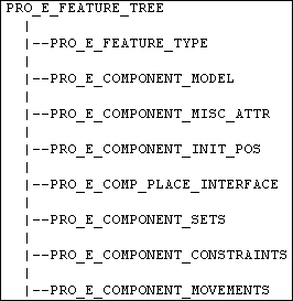
The element tree for a component assembly is documented in the header file ProAsmcomp.h and is shown in the following figure.
Top-level Feature Element tree for Component Assembly

Attributes
The element PRO_E_MISC_ATTR defines the type of component being assembled. You can also access this property through ProAsmcompTypeGet() and ProAsmcompTypeSet().
Initial Position
The element PRO_E_COMPONENT_INIT_POS defines the absolute position of the component in the absence of any parametric constraints. Its value is a ProMatrix object describing the component position. If you supply this element but no PRO_E_COMPONENT_CONSTRAINT elements, the component is assembled as packaged at this location.
If you under constrain the component, the value of this element is used in conjunction with the constraints to set the packaged
position for the component.
Constraint Sets and Mechanism Connections
The element PRO_E_COMPONENT_SETS is an array of elements of type PRO_E_COMPONENT_SET. Each of these elements is a predefined set of constraints.
Although you can define a user-defined type of constraint set containing any type and combination of constraints, the set
element is also important when used to create predefined types of sets in Creo Parametric.
Mechanism uses predefined set types to represent connections. The connection can also contain elements describing mechanism
motion axes stored for the connection.
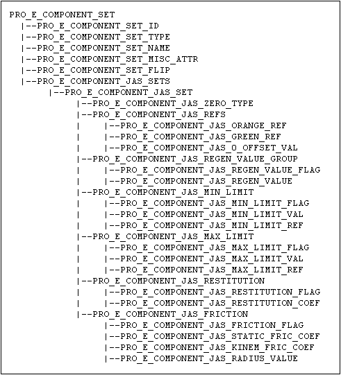
PRO_E_COMPONENT_SET

Each component set contains the following elements:
| • | PRO_E_COMPONENT_SET_ID—Specifies the component set id. This value is generated automatically by Creo Parametric upon creation of the set. The set ids should remain the same when redefining the component. |
| • | PRO_E_COMPONENT_SET_TYPE—Specifies the component set type. The following table describes the valid values in details. |
|
Component Set Type
|
Description
|
|---|---|
|
PRO_ASM_SET_TYPE_FIXED
|
A "Rigid" Mechanism connection: Connects two components so that they do not move relatively to each other.
|
|
PRO_ASM_SET_TYPE_PIN
|
A "Pin" Mechanism connection: Connects a component to a referenced axis so that the component rotates or moves along this
axis with one degree of freedom.
|
|
PRO_ASM_SET_TYPE_SLIDER
|
A "Slider" Mechanism connection: Connects a component to a referenced axis so that the component moves along the axis with
one degree of freedom.
|
|
PRO_ASM_SET_TYPE_CYLINDRICAL
|
A "Slider" Mechanism connection: Connects a component so that it moves along and rotates about a specific axis with two degrees
of freedom.
|
|
PRO_ASM_SET_TYPE_PLANAR
|
A "Planar" Mechanism connection: Connects components so that they move in a plane relatively to each other with two degrees
of freedom in the plane and one degree of freedom around an axis perpendicular to it.
|
|
PRO_ASM_SET_TYPE_BALL
|
A "Ball" Mechanism connection: Connects a component so that it can rotate in any direction with three degrees of freedom (360?
rotation).
|
|
PRO_ASM_SET_TYPE_WELD
|
A "Weld" Mechanism connection: Connects a component to another so that they do not move relatively to each other.
|
|
PRO_ASM_SET_TYPE_BEARING
|
A "Bearing" Mechanism connection: A combination of Ball and Slider connections with four degrees of freedom.
|
|
PRO_ASM_SET_TYPE_GENERAL
|
A "General" Mechanism connection: Has one or two configurable constraints that are identical to those in a user-defined set.
|
|
PRO_ASM_SET_TYPE_6DOF
|
A "Six Degrees of Freedom" Mechanism connection: Does not affect the motion of the component in relation to the assembly because
no constraints are applied.
|
|
PRO_ASM_SET_TYPE_GIMBAL
|
A “Gimbal” Mechanism connection: This connection behaves similar to the "Six Degrees of Freedom" connection except that in
Gimbal connection the translational degrees of freedom are locked.
|
|
PRO_ASM_SET_TYPE_SLOT
|
A "Slot" Mechanism connection: A point on a non straight trajectory. This connection has four degrees of freedom, where the
point follows the trajectory in three directions.
|
|
PRO_ASM_SET_USER_DEFINED_TYPE
|
A user defined constraint set. Legacy components which do not have defined Mechanism connections will always use this type.
|
| • | PRO_E_COMPONENT_SET_NAME—Specifies the name of the component set. |
| • | PRO_E_COMPONENT_SET_MISC_ATTR—Specifies the component set attributes. Currently, these attributes are limited to flags which enable or disable the set. |
| • | PRO_E_COMPONENT_JAS_SETS is an array of compound elements of type PRO_E_COMPONENT_JAS_SET which indicate Joint Axis Set (JAS). It represents the motion axis settings for the Mechanism connection. It consists of
the following elements—
|
Placement Constraints
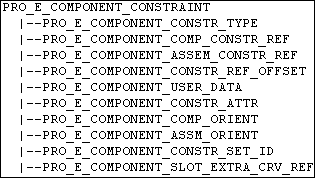
The element PRO_E_COMPONENT_CONSTRAINTS is an array of elements of type PRO_E_COMPONENT_CONSTRAINT, each representing a single component placement constraint.
PRO_E_COMPONENT_CONSTRAINT

Each constraint element contains the following elements:
| • | PRO_E_COMPONENT_CONSTR_TYPE—See discussion regarding Assembling a Component Parametrically. |
| • | PRO_E_COMPONENT_COMP_CONSTR_REF—Identifies the geometry item in the component referenced by the constraint. This element is of type Selection. |
| • | PRO_E_COMPONENT_ASSEM_CONSTR_REF—Identifies the constraint reference in the assembly. Note
this reference must include a component path referencing the top level assembly, even if the reference belongs directly to
the top level assembly.
|
| • | PRO_E_COMPONENT_CONSTR_REF_OFFSET—Gives the offset value, if the constraint type is an offset. |
| • | PRO_E_COMPONENT_USER_DATA—Specifies user data. |
| • | PRO_E_COMPONENT_CONSTR_ATTR—See discussion under Assembling a Component Parametrically. |
| • | The elements PRO_E_COMPONENT_COMP_ORIENT and PRO_E_COMPONENT_ASSM_ORIENT indicate which side of a referenced surface to be used. These values have different meanings for user-defined constraint sets and mechanism connections. See discussion under ProAsmcompconstraintAsmreferenceGet() and ProAsmcompconstraintCompreferenceGet(). |
| • | PRO_E_COMPONENT_CONSTR_SET_ID—Specifies the index of the member of the array of PRO_E_COMPONENT_SET elements that owns the constraint. |
| • | PRO_E_COMPONENT_SLOT_EXTRA_CRV_REF—Specifies the extra curve references used by a Slot connection only. This is a multivalued element. |
Component Movement in Assembly
The element PRO_E_COMPONENT_MOVEMENTS is an array of elements of type PRO_E_COMPONENT_MOVEMENT which represent movements applied to the component being assembled.
PRO_E_COMPONENT_MOVEMENT

Each movement element contains the following elements:
| • | PRO_E_COMPONENT_MOVEMENT_TYPE specifies allowed movement types |
Use the following options to move the component parallel to the reference selected and are of the following values:
| • | PRO_ASM_TRANSLATE_X |
| • | PRO_ASM_TRANSLATE_Y |
| • | PRO_ASM_TRANSLATE_Z |
Use the following options to rotate the component about the selected references.
| • | PRO_ASM_ROTATE_X |
| • | PRO_ASM_ROTATE_Y |
| • | PRO_ASM_ROTATE_Z |
| • | PRO_ASM_TWIST_FIT |
| • | PRO_E_COMPONENT_MOVEMENT_REF specifies the translational and rotational motion references. |
| • | PRO_E_COMPONENT_MOVEMENT_VALUE |
Placement via Interface
The element PRO_E_COMP_PLACE_INTERFACE is a compound element that defines an alternative assembly technique: using component interfaces to define the placement
instead of traditional constraints.
PRO_E_COMP_PLACE_INTERFACE

The element contains the following elements:
| • | PRO_E_COMP_PLACE_INTERFACE_TYPE—Specifies the interface types as follows:
Note
If this value is not set (set to 0) then component interfaces are not used to define this component.
|
| • | PRO_E_COMP_PLACE_INTERFACE_COMP—Specifies the component model interface. This should contain the component interface feature. |
| • | PRO_E_COMP_PLACE_INTERFACE_ASSEMS—Specifies an array of assembly references. If the placement type is PRO_ASM_INTFC_TO_GEOM this contains 1 or more geometric references from the assembly. If the placement type is PRO_ASM_INTFC_TO_INTFC this contains a single reference element containing the component interface feature. |