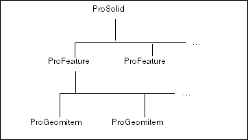
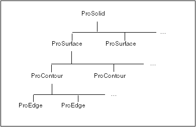
• | ProSurface—Surface, datum surface, or datum plane |
• | ProEdge—Edge |
• | ProCurve—Datum curve |
• | ProCompcrv—Composite datum curve |
• | ProQuilt—Quilt |
• | ProAxis—Axis |
• | ProPoint—Datum point |
• | ProCsys—Datum coordinate system |
|
|
|
|
|
|
|
|
|
|
|
|
|
|
|
|
• | surface—Specifies the surface of the contour. |
• | edge—Specifies the handle of the edge. |
|
|
|
|
|
|
• | An array of the XYZ coordinates of the vertices between the tessellations |
• | The two surfaces that neighbor the edge (as also provided by ProEdgeNeighborsGet()). If the edge is a single-sided edge, then the output argument returns only one surface. |
• | An array of uv pairs for the tessellation vertices in the first neighboring surface |
• | An array of uv pairs for the second neighboring surface |
• | The number of tessellation vertices |
|
|
|
|
|
|
|
|
|
|
|
|
• | PRO_SRFTESS_DEFAULT_PROJECTION—Provides the UV parameters for the tessellation points that map to a plane whose U and V extents are [0,1] each. This is the default projection. |
• | PRO_SRFTESS_PLANAR_PROJECTION—Projects the UV parameters using a planar transform, where u=x, v=y, and z is ignored. |
• | PRO_SRFTESS_CYLINDRICAL_PROJECTION—Projects the UV parameters using a cylindrical transform, where x=r*cos(theta), y=r*sin(theta), u=theta, v=z, and r is ignored. |
• | PRO_SRFTESS_SPHERICAL_PROJECTION—Projects the UV parameters onto a sphere, where x=r*cos(theta)*sin(phi), y=r*sin(theta)*sin(phi), z=r*cos(phi), u=theta, v=phi, and r is ignored. |
• | PRO_SRFTESS_NO_PROJECTION—Provides the unmodified UV parameters for the tessellation points. This is similar to using the function ProSurfaceParamEval(). |
• | PRO_SRFTESS_BOX_PROJECTION—Projects the UV parameters using the box transform. The box transformation uses planar projection to project a point from the face of the box onto the model or surface, which is opposite to the face of the box, where u = x, v = y, and z is ignored. |
• | If the function ProSurfacetessellationinputUvprojectionSet() is not used, the output tessellation will not contain any UV parameters and the function ProTessellationParamsGet() will not return any values. |
• | Specify the unmodified UV parameters obtained using PRO_SRFTESS_NO_PROJECTION as the input u and v values for the functions ProSurfaceXyzdataEval(), ProSurfaceUvpntVerify(), ProSurfaceDiameterEval(), and ProSurfacePrincipalCrvtEval(). |
|
|
|
|
|
|
• | The X, Y, and Z coordinates of the point, with respect to the model coordinates |
• | The first partial derivatives of X, Y, and Z, with respect to u and v |
• | The second partial derivatives of X, Y, and Z, with respect to u and v |
• | A unit vector in the direction of the outward normal to the surface at that point |
• | The X, Y, and Z coordinates of the point, with respect to the model coordinates |
• | The first partial derivatives of X, Y, and Z, with respect to t |
• | The second partial derivatives of X, Y, and Z, with respect to t |
• | A unit vector in the direction of the edge |
|
|
|
|
typedef struct geom_item_data_struct
{
ProType obj_type;
union
{
ProCurvedata *p_curve_data;
ProSurfacedata *p_surface_data;
ProCsysdata *p_csys_data;
} data;
} ProGeomitemdata;
1. | Get the type of equation used to describe the edge using the function ProEdgeTypeGet(). The possible types for a solid edge are as follows:
|
2. | Get the data structure for the geometry using the function ProEdgeDataGet(). For an edge, the type field is set to PRO_EDGE, and the relevant field from the union is p_curve_data. The type for that field, ProCurvedata, is itself a union that contains a field for each type of edge equation. For example, if the edge type is PRO_ENT_ARC, the relevant field in the ProCurvedata structure is the one called arc, of type ProArcdata. Each such structure contains fields for the coefficients and constants in the relevant equations (described in the Geometry Representations section), and share the same names. |
3. | When you have read the information you need from the ProGeomitemdata structure, free the memory using ProGeomitemdataFree(). |
|
|
|
|
|
|
|
• | PRO_SRF_PLANE—A plane |
• | PRO_SRF_CYL—A cylinder |
• | PRO_SRF_CONE—A cone |
• | PRO_SRF_TORUS—A torus |
• | PRO_SRF_COONS—A Coons patch |
• | PRO_SRF_SPL—A spline surface |
• | PRO_SRF_FIL—A fillet surface |
• | PRO_SRF_RUL—A ruled surface |
• | PRO_SRF_REV—A surface of revolution |
• | PRO_SRF_TABCYL—A tabulated cylinder |
• | PRO_SRF_B_SPL—A nonuniform rational B-spline (NURBS) |
• | PRO_SRF_CYL_SPL—A cylindrical spline surface |
• | periodic_in_u—Specifies if the surface is periodic in U-direction. |
• | period_in_u—Specifies the value of period in U-direction. |
• | periodic_in_v—Specifies if the surface is periodic in V-direction. |
• | period_in_v—Specifies the value of period in V-direction. |
|
|
|
|
|
|
|
|
|
|
• | p_quilt_data—The quilt data. |
• | body_or_quilt—Type of quilt data as PRO_BODY or PRO_QUILT. |
|
|
|
|
|
|
|
|
|
|
• | ProCurveTypeGet() is analogous to ProEdgeTypeGet(). |
• | ProCurveDataGet() is analogous to ProEdgeDataGet(). |
• | The value PRO_ENT_CMP_CRV specifies a composite curve. |
• | The value PRO_ENT_PARAM_CRV specifies a parametrized curve (x(t), y(t), z(t)), where x, y, and z are user-defined functions. |
• | The value PRO_ENT_SRF_CRV specifies a parameterized curve (u(t), v(t)) that exists on a surface, where u and v are user-defined functions. |
• | p_curve—The component curve. |
• | p_direction—The direction of the component. |
• | p_curve—The component curve data structure is defined by the ProCurvedata. |
• | direction—The direction of the component is defined by the ProCurveDir. |
|
|
|
|
|
|
|
|
|
|
|
|
|
|
|
|
|
• | Cylinder—The cylinder radius |
• | Torus—The distance from the axis to the generating arc |
• | Cone—The distance of the point specified from the axis |
• | Surface of revolution—The distance of the point specified from the axis |
• | Only the ProContourBoundbox3dCompute() function takes into account internal voids. |
• | The outline returned by the function ProContourBoundbox3dCompute() represents the outline box used by Creo Parametric embedded algorithms, and hence it can be slightly bigger than the outline computed directly from the surface parameters. |
• | If the selected item is a cylindrical surface, measures the distance from the central axis of the cylindrical surface. Specify PRO_B_FALSE to measure from the surface instead of the axis. |
• | If the selected item is an arc, measures the distance from the center of a circle or an arc-shaped curve or edge. Specify PRO_B_FALSE to measure from the edge instead of the center. |
• | If the selected item is a planar surface or a plane, extends the selected surface or plane to infinity in both directions only for the purpose of measuring distance. You can now measure the distance normal to the reference entity. |
• | If the selected item is linear, extends the selected straight edge or curve to infinity in both directions only for the purpose of measuring distance. You can now measure the distance normal to the reference entity. |
• | p_result—Distance between the two items |
• | pnt_1 and pnt_2—Critical point for the first and second selected items. Critical point is the actual point used for measurement. |
• | param_1 and param_2—UV parameter of the critical point for the first and second selected items |
|
|
|
|
|
|
|
|
|
|
|
|
• | PRO_FIT_PART—Computes interference between the pairs of parts in an assembly. The interference is computed only for those pairs whose volume can be calculated. The pairs whose volume could not be calculated are removed. |
• | PRO_FIT_SUB_ASSEMBLY—Computes interference between the pairs of subassemblies in an assembly, that is, computes interference between parts of different subassemblies. The interference is computed only for pairs whose volume can be calculated. The pairs whose volume could not be calculated are removed. |
• | PRO_FIT_PART_DETAILED—Computes interference between the pairs of parts in an assembly. The interference is computed for all the pairs irrespective of whether the volume can be calculated. |
• | PRO_FIT_SUB_ASSEMBLY_DETAILED—Computes interference between the pairs of subassemblies in an assembly, that is, computes interference between parts of different subassemblies. The interference is computed for all the pairs irrespective of whether the volume can be calculated. |
• | sel_1—The first part or solid body. |
• | sel_2—The second part or solid body. |
• | set_facets—The option to include facets for parts. |
• | set_quilts—The option to include quilts for parts. Note
Set the ProBoolean arguments set_facets and set_quilts to PRO_B_TRUE to include facets or quilts in the model, respectively.
|
• | inetrf_data — Specifies a pointer to the interference data. |
• | color— Specifies the color to use for highlighting the interference. |
• | hilite— Specifies if the curves and surfaces that interfere with the selected quilt must be displayed or hidden. Specify PRO_B_TRUE for displaying the interfering component and PRO_B_FALSE for hiding it. |
• | interf_data— Pointer to the interference data for the corresponding component that interferes with the quilt. |
• | p_body—Pointer to the solid body in the specified component. |
• | color— Specifies the color to be used for highlighting the interference and is defined by the enumerated data type ProColortype. |
• | hilite— Specifies if the curves and surfaces that interfere with the selected quilt must be displayed or hidden. Specify PRO_B_TRUE for displaying the interference geometry of the specified body and PRO_B_FALSE for hiding it. |
typedef struct pro_model_item
{
ProType type;
int id;
ProMdl owner;
} ProFacetSet;