Production Applications: Sheetmetal
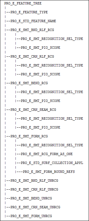
This section describes the sheet metal geometry analysis and bend table functions. It also introduces and describes the feature element trees for the sheet metal features.
Geometry Analysis
Creo TOOLKIT geometry analysis functions provide for analysis of sheet metal part geometry and ensure effective customization of sheet metal parts. These analyses include extracting part thickness data and obtaining edge and surface data for sheet metal components.
In addition, sheet metal bend edge and bend surface functions support analyses that:
•  Extract bend information associated with bend lines (K-factor, Y-factor, bend deduction, bend allowance).
•  Find bend lines when a part is in a flat state.
•  Map flat state IDs to bent state IDs.
Functions Introduced:
The function ProSmtPartThicknessGet() returns the dimension that defines the thickness of the specified sheet metal component. If the model contains the thickness parameter, then this dimension cannot be modified directly. Use the function ProParameterValueWithUnitsSet() to assign the value of the thickness parameter. If you specify a non sheet metal part, ProSmtPartThicknessGet() returns PRO_TK_BAD_CONTEXT.
The function ProSmtSurfaceTypeGet() returns the type of the specified solid surface. This enables you to determine whether a surface is created by a sheet metal feature, and to distinguish among the different types of sheet metal surfaces, such as side, white, and green.
The possible values are as follows:
•  PRO_SMT_SURF_NON_SMT—The surface was created by a solid feature.
•  PRO_SMT_SURF_SIDE—The surface is a side surface created by a sheet metal feature.
•  PRO_SMT_SURF_FACE—The surface is the face (green) surface created by a sheet metal feature.
•  PRO_SMT_SURF_OFFSET—The surface is the offset (white) surface created by a sheet metal feature.
The function ProSmtedgeContourGet() returns a complete contour that contains the specified edge. This function returns PRO_TK_BAD_CONTEXT if the edge is not on the green or white side of the specified part.
The function ProSmtOppsurfGet() returns a surface that is opposite (offset to) the specified surface.
The function ProSmtOppedgeGet() returns the edge that is opposite (offset to) the specified edge. Edge data for function ProSmtOppedgeGet() uses the following definitions:
•  An edge is lying on a green surface if one of its surfaces has SHEETMETAL TYPE = FACE.
•  An edge is lying on a white surface if one of its surfaces has SHEETMETAL TYPE = OFFSET.
•  The opposite edge to an edge must be on the surface opposite the original edge's surface and must be a geometrical offset of the original edge.
•  An edge is in a peripheral contour if, and only if the following are true:
  It is in the part geometry.
  Exactly one of its surfaces is either FACE or OFFSET.
The function ProSmtBendsrfParentGet() returns the parent of the specified surface. For example, if the specified surface is in bent position, this function returns the surface that is the most recent, unbent equivalent of the specified surface. See notes below.
The function ProSmtBendsrfChildGet() returns the active (visible) child surface of the specified, inactive (invisible) surface. A surface is active (visible) if it is in the part geometry list. See notes below.
The function ProSmtBendedgeParentGet() returns the parent of the specified edge. For example, if the specified edge is in bent position, this function returns the edge that is the most recent, unbent equivalent of the specified edge. See notes below.
The function ProSmtBendedgeChildGet() returns the active (visible) child edge of the specified, inactive (invisible) edge. An edge is active (visible) if both its surfaces are active and the edge is contained in the contours of both surfaces. See notes below.
•  Edges and surfaces in quilt geometry are also visible, but they are invalid as input to sheet metal functions.
•  Surface and edge parent and child functions use the following definitions:
  An edge or surface has a parent if the edge or surface is a result of bending or unbending another edge or surface.
  If an edge or surface is active and is a result of bending or unbending, any parent of this edge or surface that is in the chain of bends or unbends has this edge or surface as the active child.
The function ProSmtMdlIsFlatStateInstance() checks if the model is a flat state instance model.
The function ProFaminstanceIsFlatState() checks if the family instance of the model is a sheet metal flat instance or not.
The function ProSmtBendsrfInfoGet() gets all the information about the specified bend surface in a sheet metal part. You can specify as input, the face surface PRO_SMT_SURF_FACE or, the offset surface PRO_SMT_SURF_OFFSET which is created by the sheet metal feature. The cylindrical and planar surfaces, which are created by unbending the cylindrical surfaces, can be specified as input.
The following information is collected:
•  radius—Specifies the bend radius.
•  is_inside_radius—Specifies PRO_B_TRUE if the bend radius is inside. It returns PRO_B_FALSE if the bend radius is outside.
•  angle—Specifies the bend angle in degrees.
•  dev_length—Specifies the developed length of the surface.
•  dev_len_info—Specifies a structure, that contains information about the values of various parameters, which were used to calculate the developed length. The structure ProSmtDvlLenCalcInfo contains the following information:
  method—Specifies the method used to calculate the developed length. The method is specified using the enumerated data type ProDvlLenMethod.
  model—Specifies the model, whose bend allowance settings are used to calculate the developed length. Usually, the model is the part that owns the specified bend surface. A model can also be a reference part, when the specified surface has been copied from a reference part. Here the developed length is calculated according to the bend allowance settings of the reference part, or the bend allowance settings of a feature in the reference part.
  y_factor_value—Specifies the value of K-factor or Y-factor used to calculate the developed length.
Note
y_factor_value is specified only if the method used to calculate developed length is PRO_DVL_LEN_DRIVEN_BY_Y_FACTOR.
  bend_table—Specifies the name of the bend table that controls the bend allowance calculations for the developed length.
  formula—Specifies the formula that was used to calculate the developed length.
  allowance—Specifies the value of bend allowance from the bend table.
  dimension—Specifies the dimension ID associated with the developed length. If the method used to calculate developed length is PRO_DVL_LEN_DRIVEN_BY_DIMENSION, then developed length is specified manually by the user.
  driven_by_part_settings—Specifies if the developed length is driven by bend allowance settings of a part or by bend allowance settings of a feature. PRO_B_TRUE indicates that the bend allowance settings of a part are used.
Bend Tables and Dimensions
Bend table functions support reading in or removing bent table data for a sheet metal part or feature in the part.
Sheet metal dimension functions find or set whether or not developed length dimensions are driven.
Functions Introduced:
The function ProSmtPartBendtableApply() applies the specified bent table to the sheet metal part. The input argument from_file specifies whether the bend table is to be applied from memory or from the specified file.
The function ProSmtPartBendtableRemove() removes the specified bend table from the sheet metal part and the part uses the Y Factor.
The function ProSmtFeatureBendtableApply() applies the specified bent table to the sheet metal part feature. The input argument from_file specifies whether the bend table is to be applied from memory or from the specified file.
The function ProSmtFeatureBendtableRemove() sets a sheet metal feature to use the part bend table instead of the feature bend table.
The function ProSmtFeatureDevldimsGet() returns the developed length dimensions for the specified sheet metal bend or wall feature. It also returns the surfaces whose developed length these dimensions define.
The function ProSmtDevldimIsDriven() specifies whether a developed length dimension is driven or not. Use the function ProSmtDevldimDrivenSet() to set a developed length dimension to driven.
Bend Allowance Parameters
You can set the sheet metal bend allowance properties using the bend allowance parameters. These parameters can be defined using the ProParameter functions. For more information on Parameters, refer to the section Core: Parameters.
You cannot edit these bend allowance parameters.
Bend Allowance Type
Parameter Name—SMT_PART_BEND_ALLOW_FACTOR_TYPE
The parameter allows you to set the bend allowance type. You can set whether the K factor or Y factor must be used.
Type—String
Values—K factor or Y factor
Default Value—Y factor
Bend Allowance Factor Value
Parameter Name—SMT_PART_BEND_ALLOWANCE_FACTOR
The parameter allows you to set the value of the bend allowance factor.
Type—Real number
Values—Numeric value
Default Value—0.5
Bend Allowance Table Name
Parameter Name—SMT_PART_BEND_TABLE_NAME
The parameter allows you to define the name of the bend allowance table.
Type—String
Values—Can be empty or list of all the names of the bend tables from the part.
Default Value—Empty
Unattached Planar Wall Feature
A planar wall is a planar section of a sheet metal part. It can either be a primary wall (the first wall in the design), or a secondary wall (which is dependent on the primary wall). Planar walls can take any flat shape.
Creo TOOLKIT supports planar walls that are created using the Fill Tool or the Planar Wall tool. Planar walls created using the Fill Tool are unattached and may be the primary wall. Wall created using the Flat Wall tool are secondary walls that are attached to existing wall edges, and may or may not have a bend applied.
Unattached Planar Wall based on the Fill Tool
A sheet metal planar wall created based on the fill tool shares most of the same elements as the standard fill feature documented in the header file ProFlatSrf.h. The element tree should include some of the following sheet metal specific elements to generate a sheet metal feature:
•  PRO_E_IS_UNATTACHED_WALL—Has a Boolean value that specifies whether the feature is actually a flat wall.
•  PRO_E_STD_DIRECTION—Specifies the material creation direction of the sheet metal flat wall, which allows you to control the thickness of the first sheet metal wall.
•  PRO_E_STD_SMT_THICKNESS—Has a double value that specifies the wall thickness. If this feature is not the first wall feature in the part, the thickness value is irrelevant and can be 0.0. The feature inherits the thickness of the first wall feature. This element is not required and cannot be modified if the sheet metal thickness parameter is already assigned in the model.
•  PRO_E_STD_SMT_SWAP_DRV_SIDE—Specifies whether to swap the sides of the driving and the offset surfaces (the green and white surfaces of the wall).
•  PRO_E_BODY—Compound element for body options.
  PRO_E_BODY_USE—Mandatory. The valid values are :
  PRO_BODY_USE_NEW—New body created and newly created geometry is added to the new body. Always marks first wall.
  PRO_BODY_USE_SELECTED—Feature adds it's geometry to single selected body.
  PRO_E_BODY_SELECTED—Reference to the selected bodies. Mandatory if PRO_E_BODY_USE is set to PRO_BODY_USE_SELECTED, ignored otherwise. Single reference allowed.
•  PRO_E_SMT_NEW_BODY_LINKED—Specifies if the sheetmetal body is linked to a part. Mandatory if PRO_E_BODY_USE is set to PRO_BODY_USE_NEW.
For details on standard fill features, refer to the section Fill Feature.
Feature Element Tree for the Attached Flat Wall Feature
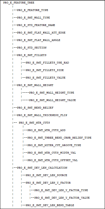
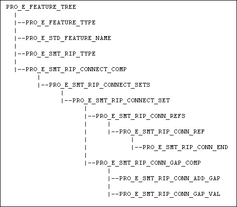
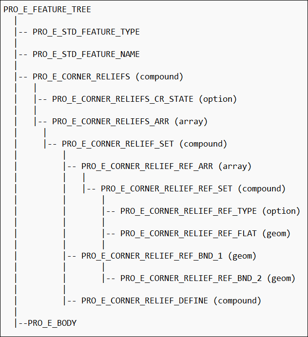
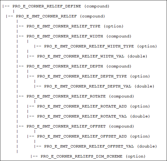
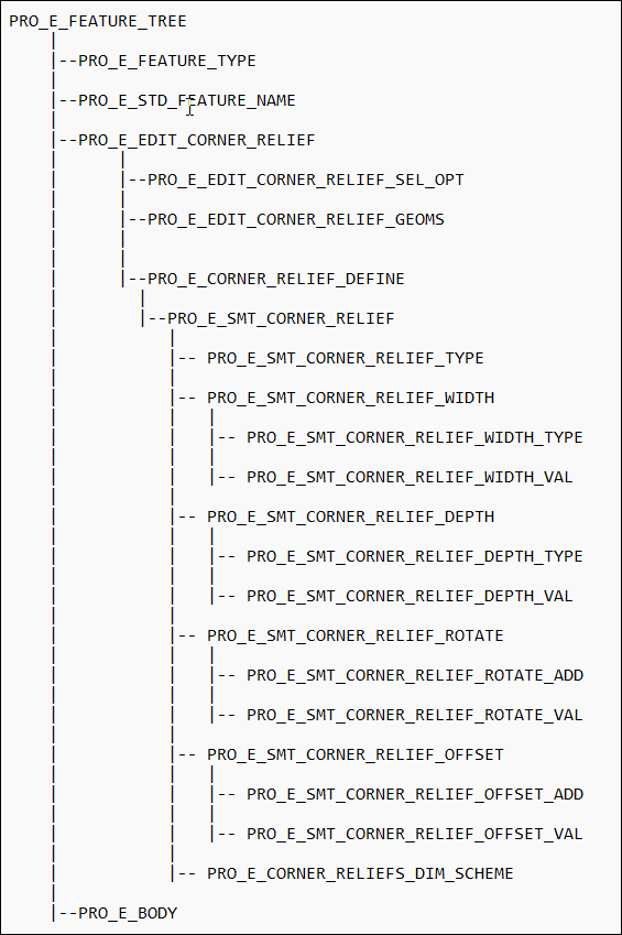
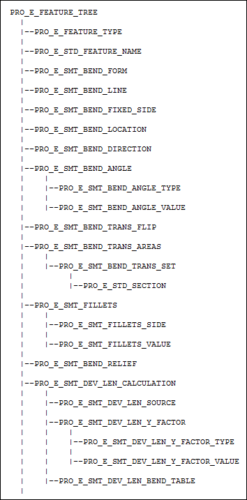
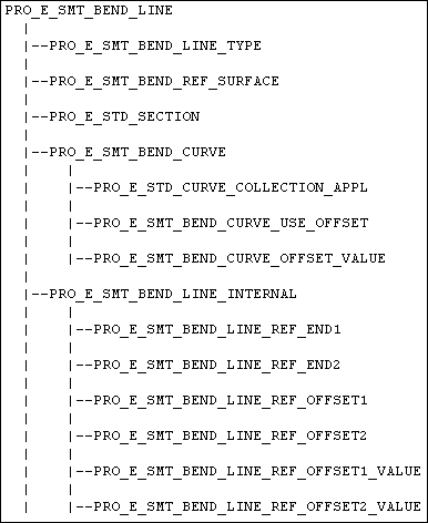
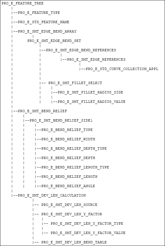
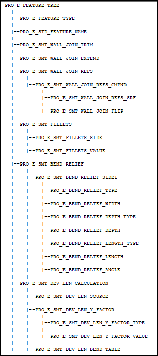
The element tree for Flat Wall feature is documented in the header file ProSmtFlatWall.h and has a simple structure. The following figure demonstrates the feature element tree structure:
Feature Element tree for Flat Wall Feature
Image
Image
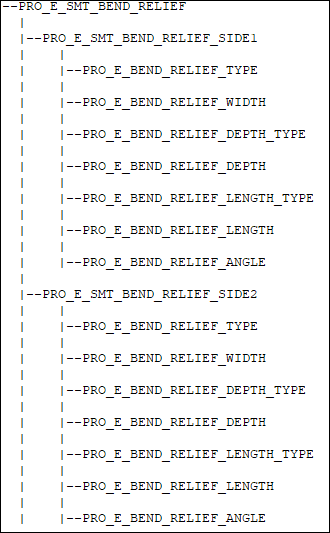
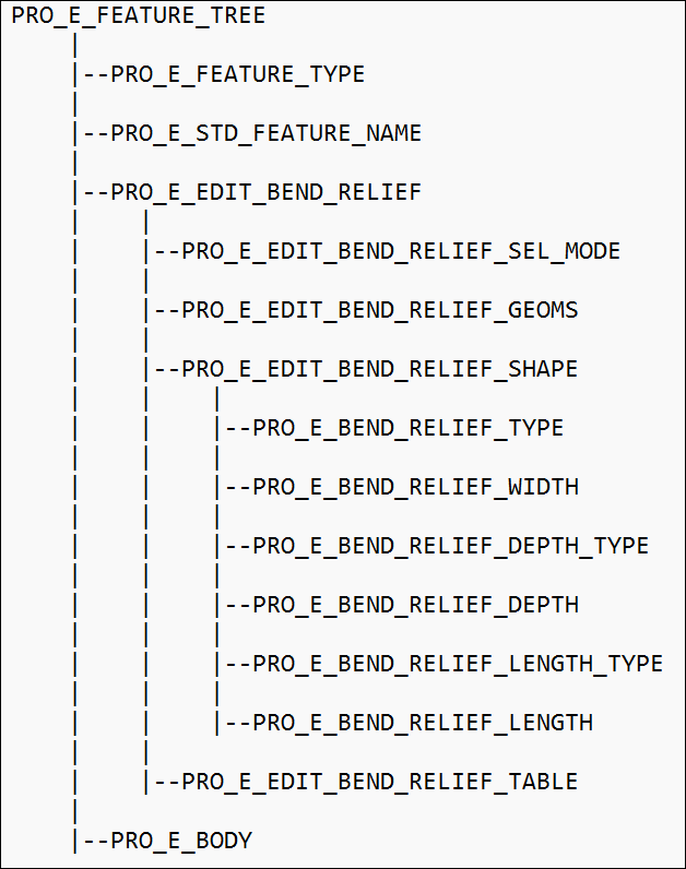
PRO_E_SMT_BEND_RELIEF
Image
The feature element tree contains no non-standard element types. The following list details special information about some of the elements in this tree:
•  PRO_E_FEATURE_TYPE—Specifies the feature type and should be PRO_FEAT_WALL.
•  PRO_E_SMT_WALL_TYPE—Specifies the wall type. For Flat Walls, this should be PRO_SMT_WALL_TYPE_FLAT.
•  PRO_E_STD_FEATURE_NAME—Specifies the name of the feature.
•  PRO_E_SMT_FLAT_WALL_ATT_EDGE—Specifies the attachment edges.
•  PRO_E_SMT_FLAT_WALL_ANGLE—Specifies the bend angle and consists of the following elements:
  PRO_E_SMT_FLAT_WALL_ANGLE_TYPE specifies the angle type and is of the following types:
  PRO_BND_ANGLE_VALUE—uses an indicated value.
  PRO_BND_ANGLE_BY_PARAM—uses the default value of the sheet metal parameter SMT_DFLT_BEND_ANGLE.
  PRO_BND_ANGLE_FLAT—uses no angle for the wall.
  PRO_E_SMT_FLAT_WALL_ANGLE_VAL—specifies the angle value.
  PRO_E_SMT_FLAT_WALL_ANGLE_FLIP—indicates whether or not to reverse the angle direction.
•  PRO_E_STD_SECTION—Specifies the wall section. Wall sections can be standard or user-defined. Standard wall sections are stored in the location <creo_loadpoint>\<version>\Common Files\text\smt. These standard sections can be retrieved; their dimensions modified, and can be added directly into the PRO_E_STD_SECTION element tree as the PRO_E_SKETCHER element. This does not require definition of a sketch plane or viewing direction, and it does not require an incomplete feature to be created as is described in the chapter Element Trees: Sketched Features. When standard sections are used to create the wall, the Creo Parametric user interface will show the correct type of section in the drop down menu (for example: Rectangle, Trapezoid, L, T).
If a user-defined section is to be used to create a flat wall, it must conform to the following restrictions:
•  It must be a 2D section
•  It must not be named the same name as one of the default section types from the Creo Parametric loadpoint.
•  It must contain a horizontal centerline and 2 coordinate systems. The centerline represents the alignment with the attachment edge, and the coordinate systems represent the edge endpoints.
•  The horizontal dimension must be specified.
When user-defined sections are used to create the wall, Creo Parametric automatically creates necessary sketching planes for the section during creation. Therefore the section may be assigned directly into the PRO_E_SKETCHER element without defining the sketch plane and without creating the feature as incomplete. After the feature has been created, the 3D section can be extracted from the feature element tree and the section can be modified to include references to other geometric entities in the sheet metal part.
•  PRO_E_SMT_FILLETS—Specifies the bend properties of the sheet metal wall:
  PRO_E_SMT_FILLETS_USE_RAD—true, a bend is applied, if false, no bend is used.
  PRO_E_SMT_FILLETS_SIDE—Specifies fillet side and has the following permitted values:
  PRO_BEND_RAD_OUTSIDE—apply the bend radius to the outside of the bend.
  PRO_BEND_RAD_INSIDE—apply the bend radius to the inside of the bend.
  PRO_BEND_RAD_PARAMETER—apply the bend radius at the dimension location set by the SMT_DFLT_RADIUS_SIDE parameter in Creo Parametric.
  PRO_E_SMT_FILLETS_VALUE—Specifies bend radius.
•  PRO_E_SMT_WALL_HEIGHT—Specifies the height of the attachment wall. It has the following elements:
  PRO_E_SMT_WALL_HEIGHT_TYPE—Specifies the manner in which the newly created wall feature attaches to the attachment edge. This element takes the following values:
  PRO_SMT_WALL_HEIGHT_AUTO—Specifies that the wall feature attaches to the attachment edge by trimming the height of the attachment wall automatically.
  PRO_SMT_WALL_HEIGHT_VALUE—Specifies that the wall feature attaches to the attachment edge by trimming the height of the attachment wall by a specified value.
  PRO_SMT_WALL_HEIGHT_APP_BEND—Specifies that the wall feature appends to the attachment edge without trimming the height of the attachment wall.
  PRO_E_SMT_WALL_HEIGHT_VALUE—specifies the value of the height of the attachment wall.
  PRO_SMT_WALL_HEIGHT_OFFSET_FROM_ORIG—Specifies that the wall feature attaches to the selected attachment edge at the specified offset distance. The distance is measured from the position of the wall, if it was attached straight to the original edge, without bend.
  PRO_SMT_WALL_HEIGHT_OFFSET_FROM_BEND—Specifies that the wall feature appends to the selected attachment edge at the specified offset distance. The distance is measured from the position of the wall, if it was attached to the original edge with an additional bend, as with the option PRO_SMT_WALL_HEIGHT_APP_BEND.
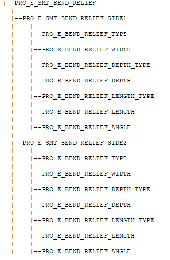
•  PRO_E_SMT_BEND_RELIEF—Specifies bend relief at the edges of the new wall feature. The relief can be specific differently on each side of the bend:
PRO_E_SMT_BEND_RELIEF_SIDE1—Specifies the first bend relief:
•  PRO_E_BEND_RELIEF_TYPE specifies relief type and has the following values:
  PRO_BEND_RLF_NONE—specifies attachment of the wall using no relief.
  PRO_BEND_RLF_RIP— specifies ripping of the material at each attachment point.
  PRO_BEND_RLF_STRETCH—specifies stretching of the material for bend relief at wall attachment point.
  PRO_BEND_RLF_RECTANGULAR—specifies adding a rectangular relief at each attachment point
  PRO_BEND_RLF_OBROUND—specifies adding an obround relief at each attachment point.
•  PRO_E_BEND_RELIEF_WIDTH—specifies the relief width (for rectangular and obround relief).
•  PRO_E_BEND_RELIEF_DEPTH—specifies relief depth (for rectangular and obround relief).
•  PRO_E_BEND_RELIEF_LENGTH_TYPE—specifies the relief length type and is defined by the enumerated data type ProBendRlfLengthType. The valid values follow:
  PRO_BEND_RLF_LENGTH_NOT_USED
  PRO_BEND_RLF_LENGTH_BLIND—Creates the bend reliefs with a length of the specified value.
  PRO_BEND_RLF_LENGTH_TO_NEXT—Creates the bend reliefs with a length to the next surface.
  PRO_BEND_RLF_LENGTH_THROUGH_ALL—Creates the bend reliefs through all surfaces.
  PRO_BEND_RLF_LENGTH_TYPE_PARAM—Uses the SMT_DFLT_BEND_REL_LENGTH_TYPE parameter value.
•  PRO_E_BEND_RELIEF_LENGTH—specifies the relief length value.
•  PRO_E_BEND_RELIEF_ANGLE—specifies relief angle (for stretch relief).
PRO_E_SMT_BEND_RELIEF_SIDE2—Includes an identical subtree for the relief applied to the second side of the wall.
•  PRO_E_SMT_WALL_THICKNESS_FLIP—Indicates whether or not to flip the thickness direction of the new wall.
•  PRO_E_SMT_DEV_LEN_CALCULATION—Specifies the method used to calculate the Developed Length dimensions for bends.
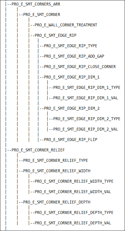
•  PRO_E_SMT_CORNERS_ARR—Specifies the edge transition for a particular corner intersection. See the section The Element Subtree for PRO_E_SMT_CORNERS_ARR for more information on corner treatment.
  PRO_E_WALL_CORNER_TREATMENT—Specifies the corner treatment that is applied to the wall. This element is defined by the enumerated data type ProWallCornerTreatment and it takes the following valid values:
  PRO_WALL_CORNER_SEAM—Specifies if the corner is created using a seam.
  PRO_WALL_CORNER_NO_SEAM—Specifies if the corner is created without using a seam.
  PRO_WALL_CORNER_IGNORE—Specifies if the corner is not created.
The Element Subtree for PRO_E_SMT_MTR_CUTS
Miter Cuts
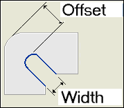
A miter cut removes material from a flat wall feature. It is controlled by two dimensions—width and offset. Offset is the distance between the end of the miter cut and the placement chain.
•  PRO_E_SMT_MTR_CUTS_ADD—Specifies the miter cuts to be added.
•  PRO_E_SMT_THREE_BEND_CRNR_RELIEF_TYPE—Specifies the three bend corner relief type and is defined by the enumerated data type ProThreeBendCornerType.
ProThreeBendCornerType—Enables you to select the type of relief for the three bend corner type in a flat wall. The valid values are:
  PRO_THREE_B_CNR_TYPE_TANGENT—Creates cut tangent in the middle bend edges to create the relief.
  PRO_THREE_B_CNR_TYPE_CLOSED—Creates a corner tangent patch to flatten as a deformation area.
  PRO_THREE_B_CNR_TYPE_OPEN—Creates linear cuts to the side bend vertices to create the relief.
  PRO_THREE_B_CNR_TYPE_RIP—Creates rips to create the relief.
  PRO_THREE_B_CNR_TYPE_NO
Note
  When PRO_E_SMT_THREE_BEND_CRNR_RELIEF_TYPE is set to PRO_THREE_B_CNR_TYPE_CLOSED, the valid options for PRO_E_SMT_MITER_CUT_GROOVE_TYPE are:
  PRO_MITER_CUT_NO_GAP
  PRO_MITER_CUT_OBROUND
  When PRO_E_SMT_THREE_BEND_CRNR_RELIEF_TYPE is set to PRO_THREE_B_CNR_TYPE_TANGENT, PRO_THREE_B_CNR_TYPE_OPEN or PRO_THREE_B_CNR_TYPE_RIP, the valid options for PRO_E_SMT_MITER_CUT_GROOVE_TYPE are:
  PRO_MITER_CUT_NO_GAP
  PRO_MITER_CUT_THROUGH_ALL
•  PRO_E_SMT_MITER_CUT_GROOVE_TYPE—Specifies the groove type to be cut in the miter and is defined by the enumerated data type ProMiterCutType.
ProMiterCutType—Enables you to select the miter cut type in a flat wall. The valid values are:
  PRO_MITER_CUT_THROUGH_ALL—Creates the miter cut groove (all the way through) to the corner relief.
If PRO_E_SMT_MITER_CUT_GROOVE_TYPE is set to PRO_MITER_CUT_THROUGH_ALL, only PRO_E_SMT_MTR_CUTS_WIDTH_VAL is used.
  PRO_MITER_CUT_OBROUND—Creates the miter cut groove as obround.
If PRO_E_SMT_MITER_CUT_GROOVE_TYPE is set to PRO_MITER_CUT_OBROUND, both PRO_E_SMT_MTR_CUTS_WIDTH_VAL and PRO_E_SMT_MTR_CUTS_OFFSET_VAL are used.
  PRO_MITER_CUT_UNDEFINED
  PRO_MITER_CUT_NO_GAP—Creates the miter cut groove with zero width.
If PRO_E_SMT_MITER_CUT_GROOVE_TYPE is set to PRO_MITER_CUT_NO_GAP, neither is used.
•  PRO_E_SMT_MTR_CUTS_WIDTH_VAL—Specifies the width value of the miter cut.
•  PRO_E_SMT_MTR_CUTS_OFFSET_VAL—Specifies the offset value of the miter cut.
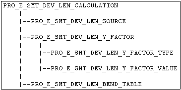
The Element Subtree for Length Calculation
•  PRO_E_SMT_DEV_LEN_SOURCE— Specifies the development length source. The valid values for this element are defined in the enumerated type ProDvlLenSrcType, and are as follows:
  PRO_DVL_SRC_NOT_DEFINED— Specifies that source is not defined
  PRO_DVL_SRC_PART_YF_AND_BTAB—uses part Y-factor and applied bend table.
  PRO_DVL_SRC_PART_YF_ONLY—uses the part Y-factor.
  PRO_DVL_SRC_FEAT_YF_AND_BTAB—uses the feature specific Y-factor and bend table.
  PRO_DVL_SRC_FEAT_BTAB_ONLY—uses the feature specific bend table.
  PRO_DVL_SRC_FEAT_YF_ONLY—uses the feature specific y-factor.
  PRO_DVL_SRC_USE_ORIGINAL—calculates the development length using the same option which was used to create the original development length when the bend was created. For example, if original development length of the bend was calculated using a part bend table, the new development will also be calculated using the same table.
•  PRO_E_SMT_DEV_LEN_Y_FACTOR—Specifies the feature Y-factor and has the following elements:
  PRO_E_SMT_DEV_LEN_Y_FACTOR_TYPE—Specifies the types of Y-factor. The valid values for this element are defined in the enumerated type ProDvlLenFactor, and are as follows:
  PRO_FACTOR_NOT_DEFINED
  PRO_FACTOR_Y
  PRO_FACTOR_K
  PRO_E_SMT_DEV_LEN_Y_FACTOR_VALUE — Specifies the value of Y- or K- factor.
•  PRO_E_SMT_DEV_LEN_BEND_TABLE — Specifies the development length bend table using the index of the bend table as loaded and stored in this model.
Note
•  Bend allowance is a method used to calculate the developed length of flat sheet metal required to make a bend of a specific radius and angle. The calculation accounts for the thickness of the sheet metal, bend radii, bend angles, and other material properties such as Y- and K-factors. Developed length fluctuates with different material types and thickness, and the bend table accounts for those variations.
•  Y- and K-factors are part constants defined by the location of the sheet metal material's neutral bend line. The neutral bend line position is based on a numeric reference for the type of sheet metal material used in your design. The numeric references range from 0 to 1, with the lower numbers representing softer material. Both the Y- and K-factors are integral elements in calculating the developed length (the length of flat sheet metal required to make a bend of a specific radius and angle) in your design.
Creating a Flat Wall Feature
Function Introduced
Use the function ProFeatureCreate() to create a Flat Wall Feature based on element tree input. For more information about ProFeatureCreate(), refer to the section Overview of Feature Creation in the Element Trees: Principles of Feature Creation section.
Redefining a Flat Wall Feature
Function Introduced
Use the function ProFeatureRedefine() to redefine a Flat Wall Feature based on the changes made in the element tree. For more information about ProFeatureRedefine(), refer to the section Feature Redefine in the Element Trees: Principles of Feature Creation section.
Accessing a Flat Wall Feature
Function Introduced
Use the function ProFeatureElemtreeExtract() to create a feature element tree that describes the contents of a Flat Wall Feature and to retrieve the element tree description of a Flat Wall Feature. For more information about ProFeatureElemtreeExtract(), refer to the section Feature Inquiry in the Element Trees: Principles of Feature Creation section.
Example 1: Creation of a Rectangular Flat Wall using a preselected edge
The sample code in UgSmtFlatWallCreate.c located at creo_toolkit_loadpoint>/protk_appls/pt_userguide/ptu_featcreat demonstrates how to create a rectangular flat wall using a preselected edge.
Flange Wall Feature
Flange wall features may be either swept or extruded.
A swept flange wall follows the trajectory formed by the chain of tangent attachment edges. You can sketch a cross section along the attachment edge and the wall sweeps along that edge. The attachment edge need not be linear and the adjacent surface need not have to be planar.
An extruded flange wall extends from one linear edge into space. You can sketch the side section of the wall and project it to a certain length in both directions.
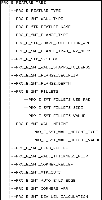
Feature Element Tree for the Flange Wall Feature
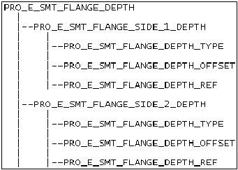
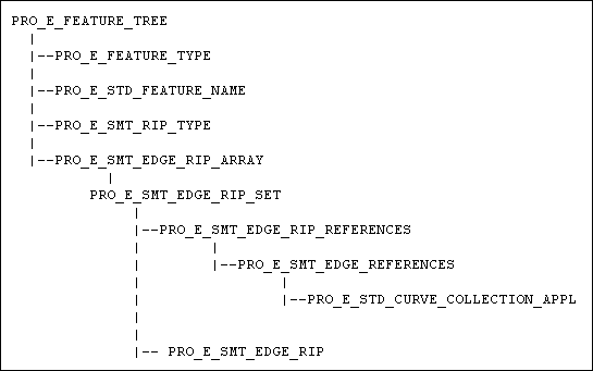
The element tree for Flange Wall feature is documented in the header file ProSmtFlangeWall.h, and has a simple structure. The following figure demonstrates the feature element tree structure:
Feature Element tree for Flange Wall Feature
Image
PRO_E_SMT_FLANGE_DEPTH
Image
PRO_E_SMT_BEND_RELIEF
Image
PRO_E_SMT_CORNER_RELIEF
Image
PRO_E_SMT_MTR_CUTS
Image
PRO_E_SMT_CORNERS_ARR
Image
PRO_E_SMT_DEV_LEN_CALCULATION
Image
Apart from the usual element for the tree root, a Flange Wall feature contains the following elements:
•  PRO_E_FEATURE_TYPE—Specifies the feature type and should be PRO_FEAT_WALL.
•  PRO_E_SMT_WALL_TYPE—Specifies the wall type and must be
  PRO_SMT_WALL_TYPE_FLANGE
  PRO_SMT_WALL_TYPE_MERGE
•  PRO_E_STD_FEATURE_NAME—Specifies the name of the feature.
•  PRO_E_SMT_FLANGE_TYPE—Specifies the type of flange wall:
  PRO_FLANGE_WALL_TYPE_2D_SWEPT—a swept flange wall in the default orientation.
  PRO_FLANGE_WALL_TYPE_3D_SWEPT—a swept flange wall with non-default directions, orientations, and start points.
  PRO_FLANGE_WALL_TYPE_EXTRUDE—a flange wall extruded from a sketching plane.
•  PRO_E_STD_CURVE_COLLECTION_APPL—Specifies the attachment edge chain. If the type is swept, this can reference multiple non-tangent edges selected as one by one or using any of the other instruction types. If the flange wall type is to be "Extruded", this must contain a One by One chain with a linear edge.
•  PRO_E_SMT_FLANGE_TRAJ_CRV_NORM—Specifies whether the flange wall should progress along the default edge chain direction or in the opposite direction.
•  PRO_E_STD_SECTION—Specifies the wall section.
Wall sections can be standard or user-defined. Standard wall sections are stored in the location <creo_loadpoint>\<version>\Common Files\text\smt. These standard sections can be retrieved, their dimensions modified, and can be added directly into the PRO_E_STD_SECTION element tree as the PRO_E_SKETCHER element. This does not require definition of a sketch plane or viewing direction, and it does not require an incomplete feature to be created as is described in the chapter Creating Sketched Features. When standard sections are used to create the wall, the Creo Parametric user interface will show the correct type of section in the drop down menu (for example: I, Arc, etc.).
If a user-defined section is to be used to create a flat wall, it must conform to the following restrictions:
•  It must be a 2D section.
•  It must not be named the same name as one of the default section types from the Creo Parametric loadpoint.
•  It must contain a horizontal centerline with a coordinate system located on it. The centerline represents the alignment with the attachment wall, and the coordinate system represents the attachment point for the section.
•  The section may optionally contain bent or straight edges. It may also contain sheet metal section entities that assist in constructing the correct swept geometry.
When user-defined sections are used to create the wall, Creo Parametric automatically creates necessary sketching planes for the section during creation. Therefore the section may be assigned directly into the PRO_E_SKETCHER element without defining the sketch plane and without creating the feature as incomplete. After the feature has been created, if the wall type is 3D swept or Extruded, the 3D section can be extracted from the feature element tree and the section can be modified to include references to other geometric entities in the sheet metal part.
•  PRO_E_SMT_WALL_SHARPS_TO_BENDS—If PRO_B_TRUE then Creo Parametric attempts to convert sharp edges in the section to bends.
•  PRO_E_SMT_FLANGE_SEC_FLIP—Specifies whether or not to flip the direction of the section for user-defined sections.
•  PRO_E_SMT_FLANGE_DEPTH—Specifies the depth of the flange, that is, the extent of the flange cover. This element governs the results for extruded flange walls only. For swept walls, the extents are governed by the rules in the element PRO_E_STD_CURV_COLLECTION_APPL, which might include trim values and boundary geometry.
•  PRO_E_SMT_FILLETS—Specifies the bend properties of the sheet metal wall.
  PRO_E_SMT_FILLETS_USE_RAD—If true, a bend is applied, if false, no bend is used.
  PRO_E_SMT_FILLETS_SIDE—Specifies fillet side and has the following permitted values:
  PRO_BEND_RAD_OUTSIDE—apply the bend radius to the outside of the bend.
  PRO_BEND_RAD_INSIDE—apply the bend radius to the inside of the bend.
  PRO_BEND_RAD_PARAMETER—apply the bend radius at the dimension location set by the SMT_DFLT_RADIUS_SIDE parameter in Creo Parametric.
  PRO_E_SMT_FILLETS_VALUE—the bend radius.
•  PRO_E_SMT_WALL_HEIGHT—Specifies the height of the attachment wall. It has the following elements:
  PRO_E_SMT_WALL_HEIGHT_TYPE—specifies the manner in which the newly created wall feature attaches to the attachment edge. This element is defined by the enumerated data type ProBendPosition and takes the following values:
  PRO_BEND_POSITION_CONSTRAINED—Specifies that the attached wall geometry is kept within the boundary of the attachment edge.
  PRO_BEND_POSITION_PROF_ON_EDGE—Specifies that the bend geometry is added while keeping the wall profile on the original attachment edge
  PRO_BEND_POSITION_BEND_OUTSIDE—Specifies that the bend geometry is added with the bend line tangent to the attachment edge.
  PRO_BEND_POSITION_OFFSET_BEND_APEX—Specifies that the offset is measured from the attachment edge to the Bend Apex.
  PRO_BEND_POSITION_OFFSET_BEND_START—Specifies that the offset is measured from the attachment edge to the Bend Start.
  PRO_E_SMT_WALL_HEIGHT_VALUE specifies the value of the height of the attachment wall.
•  PRO_E_SMT_BEND_RELIEF — Specifies bend relief. Refer to the section Feature Element Tree for the Sheetmetal Flat Wall Feature for more information on this element subtree.
•  PRO_E_SMT_WALL_THICKNESS_FLIP — Indicates whether or not to flip the thickness direction of the new wall.
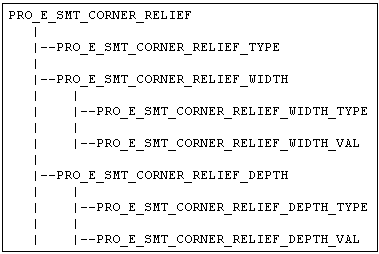
•  PRO_E_SMT_CORNER_RELIEF—Indicates a compound element representing corner relief. Corner relief is added at each intersection of a pair of bends.
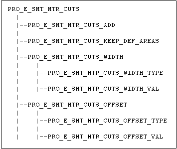
•  PRO_E_SMT_MTR_CUTS—Indicates a compound element representing miter cuts.
•  PRO_E_SMT_AUTO_EXLD_EDGE—Specifies whether to set automatic exclusion of edges. Creo Parametric uses the following set of rules and logic in order to execute the automatic wall segment excluding:
  Long wall segment has lower excluding priority than short wall segment
  Small wall segment that is neighbor to long wall has high excluding priority than other short wall segments
  A wall segment whose overlapping area at the intersection of bend surfaces of neighborhood wall segments is maximum has the highest excluding priority
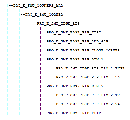
•  PRO_E_SMT_CORNERS_ARR—Specifies the edge transitions.
•  PRO_E_SMT_DEV_LEN_CALCULATION—Specifies the properties used to calculate the development length. See the section The Element Subtree for PRO_E_SMT_DEV_LEN_CALCULATION for more information.
The Element Subtree for PRO_E_SMT_FLANGE_DEPTH
PRO_E_SMT_FLANGE_DEPTH has the following elements:
•  PRO_E_SMT_FLANGE_SIDE_1_DEPTH—Specifies first side of the flange extents and has the following elements:
  PRO_WALL_LEN_TYPE_NONE—the flange does not extend in this direction.
  PRO_WALL_LEN_TYPE_BLIND—the flange extends a specified length value in this direction.
  PRO_WALL_LEN_TYPE_BLIND_SYM—the flange extends a symmetric length value in both direction. If this is used for side 1, side 2 must use PRO_WALL_LEN_TYPE_NONE.
  PRO_WALL_LEN_TYPE_TO_REF—the flange extends to a selected geometric reference.
  PRO_WALL_LEN_TYPE_TO_END—the flange extends to the end of the attachment reference.
  PRO_E_SMT_FLANGE_DEPTH_OFFSET—specifies the depth offset for blind and symmetric blind extents.
  PRO_E_SMT_FLANGE_DEPTH_REF—specifies the depth placement reference for "to ref" extents.
•  PRO_E_SMT_FLANGE_SIDE_2_DEPTH—Specifies side2 the second side of the flange. This subtree is identical to the first side.
The Element Subtree for PRO_E_SMT_CORNER_RELIEF
Corner relief is required when multiple non-tangent edges are used for attachment of the flange wall. The element PRO_E_SMT_CORNER_RELIEF represents corner relief in the feature. It has the following properties:
•  PRO_E_SMT_CORNER_RELIEF_TYPE specifies the types of corner reliefs:
  PRO_CORNER_RELIEF_NOCreo Parametric does not add relief and generates square corners.
  PRO_CORNER_RELIEF_V_NOTCHCreo Parametric adds a V notch shape cut at the corners.
  PRO_CORNER_RELIEF_CIRCULARCreo Parametric adds a circular shape relief at the corners with a radius dimension.
  PRO_CORNER_RELIEF_OBROUNDCreo Parametric adds an obround relief at the corners with a specified diameter and depth.
  PRO_CORNER_RELIEF_RECTANGULARCreo Parametric adds a rectangular relief at the corners with a specified width and depth.
•  PRO_E_SMT_CORNER_RELIEF_WIDTH a compound element with the following elements:
  PRO_E_SMT_CORNER_RELIEF_WIDTH_TYPE—This is one of the members of ProSmdRelType. See table Relation Value Types for the list of value types permitted.
  PRO_E_SMT_CORNER_RELIEF_WIDTH_VAL — This is the value for the dimension, if the width type is PRO_DIM_ENTER.
•  PRO_E_SMT_CORNER_RELIEF_DEPTH a compound element with the following elements:
  PRO_E_SMT_CORNER_RELIEF_DEPTH_TYPE—This is one of the members of ProCornerRlfDepthType. See table for the list of value types permitted.
  PRO_E_SMT_CORNER_RELIEF_DEPTH_VAL—This is the value for the dimension, if the width type is PRO_DIM_ENTER.
The Element Subtree for PRO_E_SMT_MTR_CUTS
A miter cut removes material from any profile intersecting wall segments. The miter cut is controlled by two dimensions—width and offset as shown in the figure below. Offset is the distance between the end of the miter cut to the placement chain. Creo Parametric uses half of the specified width value to cut the material of each side of the centerline of the miter cut.
Miter Cut
Image
It has the following elements:
•  PRO_E_SMT_MTR_CUTS_ADD—Specifies whether to add miter cuts.
•  PRO_E_SMT_MTR_CUTS_KEEP_DEF_AREAS—Specifies the deformation area of the miter cut. A deformation area is a section of sheet metal that helps to accurately stretch the material when you unbend the sheet metal part.
•  PRO_E_SMT_MTR_CUTS_WIDTH
  PRO_E_SMT_MTR_CUTS_WIDTH_TYPE—This is one of the members of ProMiterCutWidthType. The valid types are:
  PRO_MITER_CUT_WIDTH_TYPE_BLIND—Specifies the type PRO_DIM_ENTER
  PRO_MITER_CUT_WIDTH_TYPE_GAP—Specifies the type PRO_DIM_SMT_GAP
  PRO_MITER_CUT_WIDTH_TYPE_PARAM—Specifies the type PRO_DIM_DFLT_MITER_CUT_WIDTH
See table Relation Value Types for the list of value types permitted.
  PRO_E_SMT_MTR_CUTS_WIDTH_VAL—This is the value for the dimension, if the width type is PRO_DIM_ENTER.
•  PRO_E_SMT_MTR_CUTS_OFFSET
  PRO_E_SMT_MTR_CUTS_OFFSET_TYPE—This is one of the members of ProMiterCutOffsetType. The valid types are:
  PRO_MITER_CUT_OFFSET_TYPE_BLIND—Specifies the type PRO_DIM_ENTER
  PRO_MITER_CUT_OFFSET_TYPE_GAP—Specifies the type PRO_DIM_SMT_GAP
  PRO_MITER_CUT_OFFSET_TYPE_PARAM—Specifies the type PRO_DIM_DFLT_MITER_CUT_OFFSET
See table Relation Value Types for the list of value types permitted.
  PRO_E_SMT_MTR_CUTS_OFFSET_VAL—This is the value for the dimension, if the width type is PRO_DIM_ENTER.
The Element Subtree for PRO_E_SMT_CORNERS_ARR
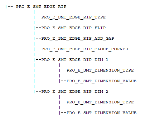
When the flange is attached to multiple non-tangent edges, it is possible to define edge transitions for each such intersection. The members of the array element PRO_E_SMT_CORNERS_ARR each define the edge transition for a particular corner intersection. Each member has a subelement called PRO_E_SMT_EDGE_RIP which contains the following:
•  PRO_E_SMT_EDGE_RIP_TYPE specifies edge treatment types and can be as follows:
  PRO_EDGE_RIP_OPEN
  PRO_EDGE_RIP_BLIND
  PRO_EDGE_RIP_MITER_CUT
  PRO_EDGE_RIP_OVERLAP
  PRO_EDGE_RIP_CONNECT
•  PRO_E_SMT_EDGE_RIP_CLOSE_CORNER specifies if the gap between the bend surfaces of a corner relief must be closed. This element is applicable only if the element PRO_E_SMT_EDGE_RIP_TYPE is set to PRO_EDGE_RIP_OPEN.
•  PRO_E_SMT_EDGE_RIP_ADD_GAP specifies whether to add a gap.
•  PRO_E_SMT_EDGE_RIP_DIM_1 specifies the first side’s properties.
  PRO_E_SMT_EDGE_RIP_DIM_1_TYPE — This is one of the members of ProEdgeRipDimType. The valid types are:
  PRO_EDGE_RIP_DIM_TYPE_BLIND—Specifies the type PRO_DIM_ENTER.
  PRO_EDGE_RIP_DIM_TYPE_GAP—Specifies the type PRO_DIM_SMT_GAP.
  PRO_EDGE_RIP_DIM_TYPE_PARAM—Specifies the type PRO_DIM_DFLT_EDGE_TREA_WIDTH.
See table Relation Value Types for the list of value types permitted.
  PRO_E_SMT_EDGE_RIP_DIM_1_VAL — This is the value for the dimension, if the width type is PRO_DIM_ENTER.
•  PRO_E_SMT_EDGE_RIP_DIM_2 specifies the second side’s properties.
  PRO_E_SMT_EDGE_RIP_DIM_2_TYPE—This is one of the members of ProEdgeRipDimType. See table Relation Value Types for the list of value types permitted.
  PRO_E_SMT_EDGE_RIP_DIM_2_VAL—This is the value for the dimension, if the width type is PRO_DIM_ENTER.
•  PRO_E_SMT_EDGE_RIP_FLIP specifies whether to flip the overlapping side.
Relation Value Types
ProSmdRelType
Description
PRO_DIM_THICK
The part thickness. It represents the parameter SMT_THICKNESS in a sheet metal part.
PRO_DIM_DOUBLE_THICK
2 x the part thickness. It represents the parameter SMT_THICKNESS in a sheet metal part.
PRO_DIM_ENTER
A user-defined value
PRO_DIM_DEF_CRN_REL_WIDTH
The value of the sheet metal Parameter SMT_DFLT_CRNR_REL_WIDTH, only allowed for corner relief width.
PRO_DIM_DEF_CRN_REL_DEPTH
The value of the sheet metal Parameter SMT_DFLT_CRNR_REL_DEPTH, only allowed for corner relief depth.
PRO_DIM_MINUS_THICK
-1 x the part thickness
PRO_DIM_MINUS_DOUBLE_THICK
-2 x the part thickness
PRO_DIM_DFLT_EDGE_TREA_WIDTH
The value of the sheet metal Parameter SMT_DFLT_EDGE_TREAT_WIDTH, only allowed for edge transition width
PRO_DIM_DFLT_MITER_CUT_WIDTH
The value of the sheet metal Parameter SMT_DFLT_MITER_CUT_WIDTH, only allowed for miter cut width
PRO_DIM_DFLT_MITER_CUT_OFFSET
The value of the sheet metal Parameter SMT_DFLT_MITER_CUT_OFFSET, only allowed for miter cut offset
PRO_DIM_THICK_1_1
1.1 x the part thickness
PRO_DIM_THICK_05
0.5 x the part thickness
PRO_DIM_SMT_GAP
The value of the sheet metal Parameter SMT_GAP
PRO_DIM_MINUS_SMT_GAP
The negative (minus) value of the sheet metal Parameter SMT_GAP
PRO_DIM_MINUS_THICK_05
-0.5 x the part thickness
PRO_DIM_DEF_BEND_RAD
The value of the sheet metal Parameter SMT_DFLT_BEND_RADIUS.
PRO_DIM_UP_TO_BEND
The relief depth type. Represents Up to Bend option for bend and corner reliefs.
PRO_DIM_TAN_TO_BEND
The relief depth type. Represents Up to Bend option for bend and corner reliefs.
PRO_DIM_DEF_BEND_ANGLE
The value of the sheet metal Parameter SMT_DFLT_BEND_ANGLE.
PRO_DIM_DEF_BEND_REL_WIDTH
The bend relief width. The value of the sheet metal Parameter SMT_DFLT_BEND_REL_WIDTH.
PRO_DIM_DEF_BEND_REL_DEPTH
The bend relief depth. The value of the sheet metal Parameter SMT_DFLT_BEND_REL_DEPTH.
PRO_DIM_DEF_BEND_REL_ANGLE
The bend relief angle. The value of the sheet metal Parameter SMT_DFLT_BEND_REL_ANGLE.
PRO_DIM_CRN_RLF_DEPTH_TYPE
The corner relief depth. The value of the sheet metal Parameter SMT_DFLT_CRNR_REL_DEPTH_TYPE.
PRO_DIM_BEND_RLF_DEPTH_TYPE
The bend relief depth. The value of the sheet metal Parameter SMT_DFLT_BEND_REL_DEPTH_TYPE.
Creating a Flange Wall Feature
Function Introduced
Use the function ProFeatureCreate() to create a Flange Wall Feature based on element tree input. For more information about ProFeatureCreate(), refer to the section Overview of Feature Creation in the Element Trees: Principles of Feature Creation section.
Redefining a Flange Wall Feature
Function Introduced
Use the function ProFeatureRedefine() to redefine a Flange Wall Feature based on the changes made in the element tree. For more information about ProFeatureRedefine(), refer to the section Feature Redefine in the Element Trees: Principles of Feature Creation section.
Accessing a Flange Wall Feature
Function Introduced
Use the function ProFeatureElemtreeExtract() to create a feature element tree that describes the contents of a Flange Wall Feature and to retrieve the element tree description of a Flange Wall Feature. For more information about ProFeatureElemtreeExtract(), refer to the section Feature Inquiry in the Element Trees: Principles of Feature Creation section.
Example 2: Creation of Flange Wall feature using Creo TOOLKIT
The sample code in UgSmtFlgWallCreate.c located at <creo_toolkit_loadpoint>/protk_appls/pt_userguide/ptu_featcreat demonstrates how to create a flange wall feature using Creo TOOLKIT. The feature is created using two external properties: the wall thickness determines the bend radius, and the attachment edge(s) are obtained from the currently selected edges in the Creo Parametric model. If a single edge is selected, it is converted to a tangent chain before it used to create the feature. The section is the 2D section handle for the I-wall section provided with Creo Parametric.
Sheet metal Wall Features
In Creo TOOLKIT, you can create extruded, revolved or swept wall features. You can specify the wall thickness, generate bends, and assign a development length calculation to the wall.
An extruded wall is drawn as a cross-section extruded in the specified direction. Similarly, the revolved and swept walls are drawn.
In Creo TOOLKIT, an extruded wall shares the same element tree as the basic Extrude feature documented in the header file ProExtrude.h. The revolved wall shares its element tree with the basic Revolve feature documented in the header file ProRevolve.h. The swept protrusion wall shares its element tree with the basic sweep feature documented in documented in the header file ProSweep.h.
The element tree should include some of the following sheet metal-specific elements to generate a sheet metal wall feature:
•  PRO_E_STD_SMT_THICKNESS—Has a double value that specifies the wall thickness. If this feature is not the first wall feature in the part, the thickness value is irrelevant and can be 0.0. The feature inherits the thickness of the first wall feature. This element is not required and cannot be modified if the sheet metal thickness parameter is already assigned in the model.
•  PRO_E_STD_SMT_SWAP_DRV_SIDE—Specifies sheet metal swap sides to switch sides of driving and offset sides.
•  PRO_E_SMT_WALL_SHARPS_TO_BENDS—Converts any sharp edges in the section to appropriate bends.
•  PRO_E_SMT_FILLETS—Refer to the section Feature Element Tree for the Sheetmetal Flat Wall Feature for the description of the element.
•  PRO_E_SMT_DEV_LEN_CALCULATION—Refer to the section Feature Element Tree for the Sheetmetal Flat Wall Feature for the description of the element.
•  PRO_E_SMT_MERGE_DATA—This compound element defines the parameters required to merge the wall geometry to an existing wall.
  PRO_E_SMT_MERGE_AUTO— The valid values for this element are:
  True—Merges the wall geometry to an existing wall in the design.
  False—Does not merge the walls.
  PRO_E_SMT_MERGE_KEEP_LINES—Controls the visibility of merged edges on surface joints. The valid values for this element are:
  True—Merged edges are visible on surface joints.
  False—Merged edges are not visible on surface joints.
•  PRO_E_BODY_USE—Mandatory. Specifies the body to add geometry to. The valid values are:
  PRO_BODY_USE_NEW—The geometry in the feature is stored in the first wall. Same as solid.
  PRO_BODY_USE_SELECTED—The geometry in the feature is stored in the single selected body. Same as solid.
•  PRO_E_SMT_NEW_BODY_LINKED—Specifies if the sheetmetal body is linked to a part. Mandatory if PRO_E_BODY_USE is set to PRO_BODY_USE_NEW.
For details on the basic Extrude and Revolve features, refer to the section Element Trees: Extrude and Revolve.
For details on the basic Sweep feature, refer to the section Element Trees: Sweep.
Sheet metal Cut Features
A sheet metal cut removes material from the walls it encounters.
In Creo TOOLKIT, a sheet metal cut feature shares the same element tree as the basic extrude feature or the solidify feature or the thicken feature. The element tree should include some of the following sheet metal cut-specific elements to generate a sheet metal cut feature:
•  PRO_E_IS_SMT_CUT—If true this feature is a sheet metal cut, otherwise it is a solid cut. It is applicable only in sheet metal parts.
•  PRO_E_SMT_CUT_NORMAL_DIR—This element defines the surface to which the section projection will be normal. The projection normal specifies the side of the sheemetal wall from which the sketched curve splits the wall. The values for this element are as follows:
  PRO_SMT_CUT_DRVSIDE_GREEN—Specifies the normal to the driven surface. This is a direction from the green side to the white side of the sheet metal wall. This is the default value.
  PRO_SMT_CUT_DRVSIDE_WHITE—Specifies the normal to the offset surface. This is a direction from the white side to the green side of the sheet metal wall.
For details on the basic Extrude feature, see the section The Element Tree for Extruded Features.
For details on the basic Solidify feature, see the section Solidify Feature.
For details on the basic Thicken feature, see the section Thicken Feature.
The extrude feature has additional optional element PRO_E_SMT_PUNCH_TOOL_DATA. This compound element defines sheet metal cut that is used to cut and relieve sheet metal walls. It is used in sheet metal manufacturing. It is applicable to sheet metal cuts, made by the Punch UDF. It defines the parameters related to the punch feature.
The compound element PRO_E_SMT_PUNCH_TOOL_DATA contains the following elements:
•  PRO_E_SMT_PUNCH_TOOL_ATTR—Specifies the symmetry flag for the Manufacturing UDF Punch Tool. The valid values for this element are:
  PRO_PUNCH_TOOL_ATTR_SYM_NONE—Specifies that the tool is not symmetric about any axis.
  PRO_PUNCH_TOOL_ATTR_SYM_X—Specifies that the tool is symmetrical about the X-axis of the coordinate system
  PRO_PUNCH_TOOL_ATTR_SYM_Y—Specifies that the tool is symmetrical about the Y-axis of the coordinate system.
  PRO_PUNCH_TOOL_ATTR_SYM_XY—Specifies that the tool is symmetrical about both the X and Y-axis of the coordinate system.
•  PRO_E_SMT_PUNCH_TOOL_NAME—Specifies the name of the Manufacturing UDF punch tool used.
For sheet metal cuts and punches, you can specify if the punch axis point must be created. A punch axis point is a reference point that moves with a feature during both, the unbend and bend back operations. In the element PRO_E_SMT_PUNCH_AXIS_PNT, specify PRO_B_TRUE to create the punch axis point in the sheet metal feature.
Extend Wall Feature
The Extend Wall feature allows you to extend an attachment wall with a straight edge.
Feature Element Tree for the Extend Wall Feature
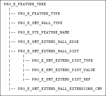
The element tree for the Extend Wall feature is documented in the header file ProSmtExtendWall.h. The following figure shows the feature element tree structure.
Feature Element Tree for Extend Wall Feature
Image
PRO_E_SMT_EXTEND_WALL_EXTENSIONS_CMP
Image
The elements in this tree are described as follows:
•  PRO_E_FEATURE_TYPE—Specifies the feature type and should be PRO_FEAT_WALL.
•  PRO_E_SMT_WALL_TYPE—Specifies the sheet metal wall type and its value is PRO_SMT_WALL_TYPE_EXTEND.
•  PRO_E_STD_FEATURE_NAME—Specifies the feature name.
•  PRO_E_SMT_EXTEND_WALL_EDGE—Specifies the edge of the attachment wall you select for extension.
•  PRO_E_SMT_EXTEND_WALL_DIST—Specifies the distance properties for the attachment wall to be extended. This compound element consists of the following elements:
  PRO_E_SMT_EXTEND_DIST_TYPE—Specifies the distance type used for extension. It takes the following values:
  PRO_EXTEND_DIST_BY_VALUE—Specifies that the attachment wall is extended by a specified value and remains parallel to the selected edge.
  PRO_EXTEND_DIST_TO_THROUGH_UNTIL—Specifies that the attachment wall is extended normally to the selected edge until it intersects the referenced plane.
  PRO_EXTEND_DIST_TO_SELECTED—Specifies that the attachment wall is extended normally to the selected edge until it intersects the referenced plane and remains parallel to the selected edge.
  PRO_E_SMT_EXTEND_DIST_VALUE—Specifies the distance value. This element is applicable only if the element PRO_E_SMT_EXTEND_DIST_TYPE has the value PRO_EXTEND_DIST_BY_VALUE.
  PRO_E_SMT_EXTEND_DIST_REF—Specifies the plane or surface selected as the reference. This element is applicable only if the element PRO_E_SMT_EXTEND_DIST_TYPE has the value PRO_EXTEND_DIST_TO_THROUGH_UNTIL or PRO_EXTEND_DIST_TO_SELECTED.
•  PRO_E_SMT_EXTEND_WALL_EXTENSIONS_CMP—Specifies the extension properties of the two sides of the attachment wall.
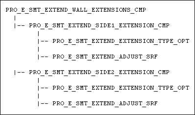
The Element Subtree for PRO_E_SMT_EXTEND_WALL_EXTENSIONS_CMP
PRO_E_SMT_EXTEND_WALL_EXTENSIONS_CMP is a compound element and consists of the following elements:
•  PRO_E_SMT_EXTEND_SIDE1_EXTENSION_CMP—Specifies the extension properties of the side 1. This compound element consists of the following elements:
  PRO_E_SMT_EXTEND_EXTENSION_TYPE_OPT—Specifies the extension type. It is given by the enumerated type ProExtendExtensionType and takes the following values:
  PRO_EXTEND_EXT_NORMAL_TO_EDGE—Specifies that the side 1 of the attachment wall is extended normal to the selected edge.
  PRO_EXTEND_EXT_ALONG_BOUND_EDGE—Specifies that the side 1 of the attachment wall is extended along the boundary of the selected edge.
  PRO_E_SMT_EXTEND_ADJUST_SRF—Specifies whether the surface adjacent to side 1 of the extended edge is also extended. The values for this element are specified by the enumerated type ProExtendAdjSrf and are as follows:
  PRO_EXTEND_ADJ_SRF_FALSE
  PRO_EXTEND_ADJ_SRF_TRUE
•  PRO_E_SMT_EXTEND_SIDE2_EXTENSION_CMP—Specifies the extension properties of the side 2. This compound element consists of the same elements as the element PRO_E_SMT_EXTEND_SIDE1_EXTENSION_CMP.
Creating a Extend Wall Feature
Function Introduced
Use the function ProFeatureCreate() to create a Extend Wall feature based on the element tree definition. For more information about ProFeatureCreate(), refer to the Overview of Feature Creation section in the Element Trees: Principles of Feature Creation section.
Redefining a Extend Wall Feature
Function Introduced
Use the function ProFeatureRedefine() to redefine a Extend Wall feature based on the changes made in the element tree. For more information about ProFeatureRedefine(), refer the Feature Redefine section in the Element Trees: Principles of Feature Creation section.
Accessing a Extend Wall Feature
Function Introduced
Use the function ProFeatureElemtreeExtract() to retrieve the element tree description of the Extend Wall feature. For more information about ProFeatureElemtreeExtract(), refer the Feature Inquiry section in the Element Trees: Principles of Feature Creation section.
Split Area Feature
You can split a sheet metal wall using a sketched curve with the Split Area feature. When you split a sheet metal wall, no side surfaces are created.
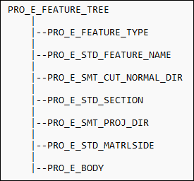
Feature Element Tree for the Split Area Feature
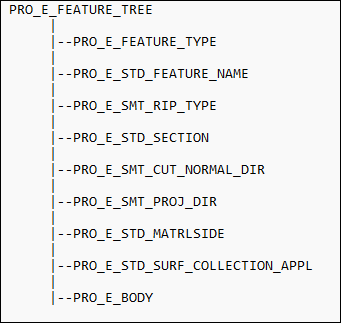
The element tree for the Split Area feature is documented in the header file ProSmtSplitArea.h. The following figure shows the feature element tree structure.
Feature Element Tree for Split Area Feature
Image
The elements in this tree are as follows:
•  PRO_E_FEATURE_TYPE—Specifies the feature type and should be PRO_FEAT_DEFORM_AREA.
•  PRO_E_STD_FEATURE_NAME—Specifies the name of the feature.
•  PRO_E_SMT_CUT_NORMAL_DIR—Specifies the normal of projection. The projection normal specifies the side of the sheemetal wall from which the sketched curve splits the wall. The values for this element are as follows:
  PRO_SMT_CUT_DRVSIDE_GREEN—Specifies the normal to the driven surface. This is a direction from the green side to the white side of the sheet metal wall. This is the default value.
  PRO_SMT_CUT_DRVSIDE_WHITE—Specifies the normal to the offset surface. This is a direction from the white side to the green side of the sheet metal wall.
•  PRO_E_STD_SECTION—Specifies the sketch selected for the split. You can create a new section or select an internal sketch from the model.
•  PRO_E_SMT_PROJ_DIR—Specifies the projection direction. It is specified by the enumerated type ProSmtProjDir. The valid values are:
  PRO_SMT_PROJ_DIR_ONE—Specifies the projection to one side. This is the default value.
  PRO_SMT_PROJ_DIR_TWO—Specifies the projection to the opposite side.
  PRO_SMT_PROJ_DIR_BOTH—Specifies the projection to both the sides.
•  PRO_E_STD_MATRLSIDE—Specifies the direction in which the area of the sheet metal wall is split. It is specified by the enumerated type ProSplitAreaMatSide. The valid values are:
  PRO_SPLITAREA_MATSIDE_ONE—Specifies the split in one direction.
  PRO_SPLITAREA_MATSIDE_TWO—Specifies the split in the opposite direction. This is the default value.
•  PRO_E_BODY—Specifies the body options. The valid values are:
  PRO_E_BODY_USE—must be PRO_BODY_USE_SELECTED
  PRO_E_BODY_SELECT—must contain a single selected body
Creating a Split Area Feature
Function Introduced
Use the function ProFeatureCreate() to create a Split Area feature based on the element tree definition. For more information about ProFeatureCreate(), refer the Overview of Feature Creation section in the Element Trees: Principles of Feature Creation section.
Redefining a Split Area Feature
Function Introduced
Use the function ProFeatureRedefine() to redefine a Split Area feature based on the changes made in the element tree. For more information about ProFeatureRedefine(), refer the Feature Redefine section in the Element Trees: Principles of Feature Creation section.
Accessing a Split Area Feature
Function Introduced
Use the function ProFeatureElemtreeExtract() to retrieve the element tree description of the Split Area feature. For more information about ProFeatureElemtreeExtract(), refer the Feature Inquiry section in the Element Trees: Principles of Feature Creation section.
Punch and Die Form Features
A Form is a sheet metal wall molded by a template (reference part). Merging the geometry of a reference part creates the Form feature.
Punch Form feature molds the sheet metal wall using only the reference part geometry whereas Die Form feature molds the sheet metal using the reference part to form the geometry (convex or concave) surrounded by a bounding plane.
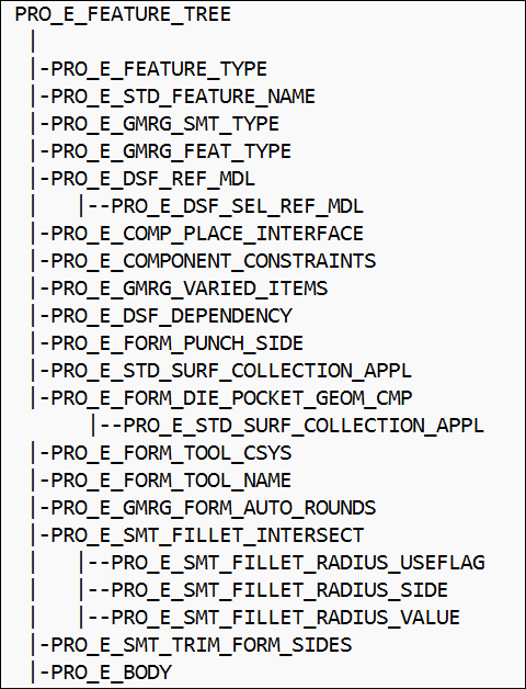
Feature Element Tree for the Punch and Die Form Features
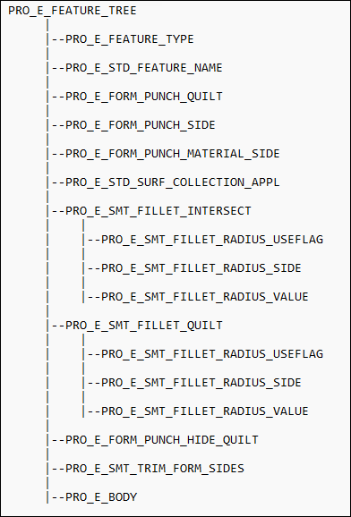
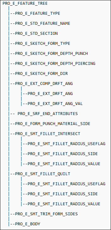
The element tree for the Punch and Die Form features is documented in the header file ProSmtForm.h and can be used to create both punch and die form features. The following figure shows the feature element tree structure:
Feature Element Tree for Punch Form Feature
Image
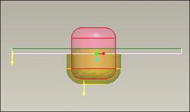
PRO_SMT_SURF_FACE
Image
The surface is the face (green) surface created by a sheet metal feature.
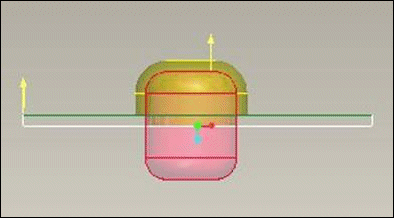
PRO_SMT_SURF_OFFSET
Image
The surface is the offset (white) surface created by a sheet metal feature.
The elements in this tree are as follows:
•  PRO_E_FEATURE_TYPE—Specifies the feature type and should be PRO_FEAT_GEN_MERGE.
•  PRO_E_STD_FEATURE_NAME—Specifies the name of the feature.
•  PRO_E_GMRG_SMT_TYPE—Specifies the type of sheet metal feature. The values for this element are specified by the enumerated type ProGenMergeSmtType and the valid values are:
  PRO_GEN_MERGE_SMT_TYPE_FORM—Specifies the Punch Form in all the versions.
Note
Use the element PRO_GEN_MERGE_SMT_TYPE_FORM_PUNCH instead of PRO_GEN_MERGE_SMT_TYPE_FORM from Creo Parametric3.0 onwards.
  PRO_GEN_MERGE_SMT_TYPE_FORM_PUNCH—Specifies the Punch Form feature for parts created in Creo Parametric3.0 onward.
  PRO_GEN_MERGE_SMT_TYPE_NOT_SMT—Specifies a merge, inheritance or any other type of General Merge feature.
  PRO_GEN_MERGE_SMT_TYPE_FORM_DIE—Specifies the Die Form feature.
•  PRO_E_GMRG_FEAT_TYPE—Specifies the type of General Merge feature.
Note
For General Merge feature of type PRO_GEN_MERGE_TYPE_MERGE, the element PRO_E_DSF_DEPENDENCY can be set to PRO_DSF_UPDATE_AUTOMATICALLY only.
For more information on the types of General Merge features, refer the General Merge (Merg section in the Assembly: Data Sharing Features section.
•  PRO_E_DSF_REF_MDL—Specifies the punch or die model used to create the Punch or Die Form feature. It consists of the following element:
  PRO_E_DSF_SEL_REF_MDL—Specifies the selected punch or die model.
•  PRO_E_COMP_PLACE_INTERFACE—Specifies the assembly component interfaces used to define the placement of the punch or die model in the sheet metal geometry. For more information on the elements contained by the placement interfaces element, refer the Placement via Interface section in the Assembly: Assembling Components section.
•  PRO_E_COMPONENT_CONSTRAINTS—Specifies the assembly component constraints used to define the placement of the punch or die model in the sheet metal geometry. For more information on the component constraints elements, refer the Placement Constraints section in the Assembly: Assembling Components section.
Note
The placement by coordinate system option in the Creo Parametric user interface for the Punch or Die Form feature is not available via Creo Parametric TOOLKIT. To place the model in the sheet metal geometry using a coordinate system, define a coordinate system feature in the sheet metal model and use it for placement.
•  PRO_E_GMRG_VARIED_ITEMS—Specifies a pointer element that defines the Inheritance feature varied items and their values. This element is available only when the Punch or Die Form feature is of the type PRO_GEN_MERGE_TYPE_INHERITANCE.For more information on this element, refer the Inheritance Feature and Flexible Component Variant Items section in the Assembly: Data Sharing Features section.
•  PRO_E_DSF_DEPENDENCY—Specifies the dependency type. The values for this element are specified by the enumerated type ProDsfDependency.
Note
From Creo Parametric 3.0 onward, the enumerated type ProDsfDependency has been deprecated. Use the enumerated type ProDSFDependency instead.
The valid values for the dependency status are:
  PRO_DSF_UPDATE_AUTOMATICALLY—Specifies that the geometry of the Punch or Die Form feature depends upon the geometry of the model used during feature creation. The Punch or Die Form feature reflects all the changes made in the parent model.
Note
From Creo Parametric 3.0 onward, the value PRO_DSF_DEPENDENT has been deprecated. Use the enumerated value PRO_DSF_UPDATE_AUTOMATICALLY instead.
  PRO_DSF_UPDATE_MANUALLY—Specifies that the geometry of the Punch or Die Form feature is independent of the geometry of the model used during feature creation. If you update the model, the feature does not change.
Note
From Creo Parametric 3.0 onward, the value PRO_DSF_INDEPENDENT has been deprecated. Use the enumerated value PRO_DSF_UPDATE_MANUALLY instead.
  PRO_DSF_NO_DEPENDENCY—Specifies that there is no dependency between the geometry of the Punch or Die Form feature and the geometry of the Punch or Die model used during feature creation.
Note
All the dependency statuses specified in the enumerated type ProDsfDependency are defined in the header file ProDataShareFeat.h. For more information on the values, refer to the section Feature Element Tree in Assembly: Data Sharing Features.
•  PRO_E_FORM_PUNCH_SIDE—Specifies the Punch direction. The direction specifies a side of a wall from which the model penetrates the sheet metal geometry. The values for this element are specified by the enumerated type ProSmtSurfType. The surface types are as follows:
  PRO_SMT_SURF_FACE—The punch model moves in a direction from the green side to the white side of the sheetemetal model. Refer to the figure PRO_SMT_SURF_FACE
  PRO_SMT_SURF_OFFSET—The punch model moves in a direction from the white side to the green side of the sheet metal model. Refer to the figure PRO_SMT_SURF_OFFSET.
•  PRO_E_STD_SURF_COLLECTION_APPL—Specifies a collection of surfaces to be excluded from the Punch or Die model during feature creation.
•  PRO_E_FORM_DIE_POCKET_GEOM_CMP—Compound element. Specify this element only if the enumerated type ProGenMergeSmtType is set to PRO_GEN_MERGE_SMT_TYPE_FORM_DIE type.
Note
This element cannot be used for creating Punch Form features and is specific to Die Form features only.
•  PRO_E_STD_SURF_COLLECTION_APPL—Specifies the collection of selected surfaces to be used for Pocket Geometry during the feature creation.
•  PRO_E_FORM_TOOL_CSYS—Specifies the reference coordinate system used during the manufacturing process. The coordinate system in the Punch model is used by default.
•  PRO_E_FORM_TOOL_NAME—Specifies the name of the manufacturing tool used to create the Punch or Die model. The name specified by the SMT_FORM_TOOL_NAME parameter in the model is used by default.
•  PRO_E_GMRG_FORM_AUTO_ROUNDS—Specifies the ProBoolean option to round the non-placement sharp edges (that do not lie on the placement surface). This optional element uses a constant outside radius of value equal to the thickness of the original sheet metal part.
•  PRO_E_SMT_FILLET_INTERSECT—Specifies the option to round the placement sharp edges (that lie on the placement surface and intersect the sheet metal geometry). This optional element consists of the following elements:
  PRO_E_SMT_FILLET_RADIUS_USEFLAG—Specifies whether a fillet radius is used.
  PRO_E_SMT_FILLET_RADIUS_SIDE—Specifies the radius direction, that is, outside or inside. The values for this element, specified by the enumerated type ProSmdRadType, are as follows:
  PRO_BEND_RAD_OUTSIDE—The radius is applied to the outside of the sheet metal geometry.
  PRO_BEND_RAD_INSIDE—The radius is applied to the inside of the sheet metal geometry.
  PRO_E_SMT_FILLET_RADIUS_VALUE — Specifies the radius value.
•  PRO_E_SMT_TRIM_FORM_SIDES—Trim edges of sheared form. Specifies if Creo Parametric applies trimming of sheet metal side surfaces during form feature generation. The valid values for this element follow:
  PRO_B_TRUE
  PRO_B_FALSE
•  PRO_E_BODY—Specifies the body options. The valid values are:
  PRO_E_BODY_USE—must be PRO_BODY_USE_SELECTED
  PRO_E_BODY_SELECT—must contain a single selected body
Creating a Punch or Die Form Feature
Function Introduced
Use the function ProFeatureCreate() to create a Punch or Die Form feature based on the element tree definition. For more information about ProFeatureCreate(), refer the Overview of Feature Creation section in the Element Trees: Principles of Feature Creation section.
Redefining a Punch or Die Form Feature
Function Introduced
Use the function ProFeatureRedefine() to redefine a Punch or Die Form feature based on the changes made in the element tree. For more information about ProFeatureRedefine(), refer the Feature Redefine section in the Element Trees: Principles of Feature Creation section.
Accessing a Punch or Die Form Feature
Function Introduced
Use the function ProFeatureElemtreeExtract() to retrieve the element tree description of the Punch or Die Form feature. For more information about ProFeatureElemtreeExtract(), refer the Feature Inquiry section in the Element Trees: Principles of Feature Creation section.
Quilt Form Feature
The Quilt Form feature molds the sheet metal wall using a referenced closed or open datum quilt.
Feature Element Tree for the Quilt Form Feature
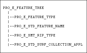
The element tree for the Quilt Form feature is documented in the header file ProSmtPunchQuilt.h. The following figure shows the feature element tree structure:
Feature Element Tree for Quilt Form Feature
The elements in this tree are as follows:
•  PRO_E_FEATURE_TYPE—Specifies the feature type and should be PRO_FEAT_PUNCH_QUILT.
•  PRO_E_STD_FEATURE_NAME—Specifies the name of the feature.
•  PRO_E_FORM_PUNCH_QUILT—Specifies the referenced datum quilt. The geometry of the referenced quilt is merged with the sheet metal part.
•  PRO_E_FORM_PUNCH_SIDE—Specifies the punch direction. The punch direction specifies a side of a wall from which the punch model penetrates the sheet metal geometry. The values for this element are specified by the enumerated type ProSmtSurfType. The surface types are as follows:
  PRO_SMT_SURF_FACE—The punch model moves in a direction from the green side to the white side of the sheetemetal model. Refer to the figure PRO_SMT_SURF_FACE.
  PRO_SMT_SURF_OFFSET—The punch model moves in a direction from the white side to the green side of the sheet metal model. Refer to the figure PRO_SMT_SURF_OFFSET.
•  PRO_E_FORM_PUNCH_MATERIAL_SIDE — Specifies whether the resultant sheet metal geometry lies inside or outside the referenced quilt after the feature is created. The geometry is placed inside or outside the referenced quilt using the thickness value of the original sheet metal part. The values for this element, specified by the enumerated type ProSmdPunchMatSide,are as follows:
  PRO_SMT_PUNCH_MAT_INSIDE
  PRO_SMT_PUNCH_MAT_OUTSIDE
•  PRO_E_STD_SURF_COLLECTION_APPL — Specifies a collection of surfaces to be excluded from the referenced quilt when the feature is created.
•  PRO_E_SMT_FILLET_INTERSECT—Specifies the set of fillets that are added to the contours created by the intersection of the referenced quilt with the sheet metal part. This element consists of the following elements:
  PRO_E_SMT_FILLET_RADIUS_USEFLAG—Specifies whether a fillet radius is used.
  PRO_E_SMT_FILLET_RADIUS_SIDE—Specifies the radius direction (outside or inside). The values for this element, specified by the enumerated type ProSmdRadType, are as follows:
  PRO_BEND_RAD_OUTSIDE—The radius is applied to the outside of the sheet metal geometry.
  PRO_BEND_RAD_INSIDE—The radius is applied to the inside of the sheet metal geometry.
  PRO_E_SMT_FILLET_RADIUS_VALUE—Specifies the radius value.
•  PRO_E_SMT_FILLET_QUILT—Specifies the set of fillets that are added to sharps (edges between non-tangent goemetries) on the referenced quilt. This element consists of the same set of elements as PRO_E_SMT_FILLET_INTERSECT.
•  PRO_E_FORM_PUNCH_HIDE_QUILT—Specifies whether the referenced quilt will be hidden in the feature. The values for this element, specified by the enumerated type ProSmdPunchHideQuilt, are as follows:
  PRO_SMT_PUNCH_HIDE_ORIGINAL
  PRO_SMT_PUNCH_KEEP_ORIGINAL
•  PRO_E_SMT_TRIM_FORM_SIDES—Trim edges of sheared form. Specifies if Creo Parametric applies trimming of sheet metal side surfaces during form feature generation. The valid values for this element follow:
  PRO_B_TRUE
  PRO_B_FALSE
•  PRO_E_BODY—Specifies the body options. The valid values are:
  PRO_E_BODY_USE—must be PRO_BODY_USE_SELECTED
  PRO_E_BODY_SELECT—must contain a single selected body
Creating a Quilt Form Feature
Function Introduced
Use the function ProFeatureCreate() to create a Quilt Form feature based on the element tree definition. For more information about ProFeatureCreate(), refer the Overview of Feature Creation section in the Element Trees: Principles of Feature Creation section.
Redefining a Quilt Form Feature
Function Introduced
Use the function ProFeatureRedefine() to redefine a Quilt Form feature based on the changes made in the element tree. For more information about ProFeatureRedefine(), refer the Feature Redefine section in the Element Trees: Principles of Feature Creation section.
Accessing a Quilt Form Feature
Function Introduced
Use the function ProFeatureElemtreeExtract() to retrieve the element tree description of the Quilt Form feature. For more information aboutProFeatureElemtreeExtract(), refer the Feature Inquiry section in the Element Trees: Principles of Feature Creation section.
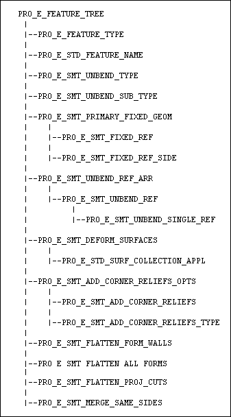
Flatten Form Feature
The Flatten Form feature allows you to flatten existing Form features in your model.
Feature Element Tree for Flatten Form Feature
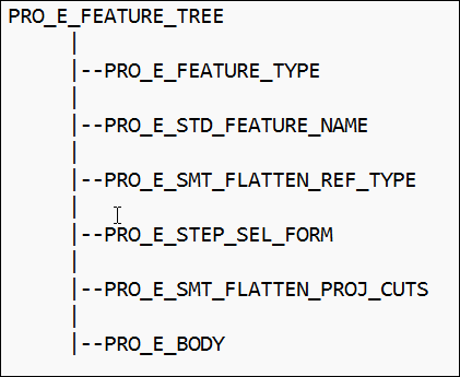
The element tree for a Flatten Form feature is documented in the header file ProSmtFlattenForm.h and has a simple structure. The following figure demonstrates the structure of the feature element tree.
Flatten Form Element Tree
Image
The elements in this tree are described as follows:
•  PRO_E_FEATURE_TYPE—Specifies the feature type and should be PRO_FEAT_FLATTEN.
•  PRO_E_STD_FEATURE_NAME—Specifies the name of the feature.
•  PRO_E_SMT_FLATTEN_REF_TYPE—Specifies the selection type for the Form features to be flattened. It is specified by the enumerated type ProFlattenRefType. The valid selection types are:
  PRO_FLATTEN_FORM_REFSEL—Specifies the type where you select an array of Form features from the model. This is the default value.
  PRO_FLATTEN_FORM_ALLSEL—Specifies the type where Creo Parametric finds and selects all the Form features from the model.
•  PRO_E_STEP_SEL_FORM—Specifies the array of Form features you select.
•  PRO_E_SMT_FLATTEN_PROJ_CUTS—Specifies if cuts must be projected to the flattened form.
•  PRO_E_BODY—Specifies the body options. Valid only when PRO_E_SMT_FLATTEN_REF_TYPE is PRO_FLATTEN_FORM_ALLSEL
  PRO_E_BODY_USE—must be PRO_BODY_USE_SELECTED
  PRO_E_BODY_SELECT—must contain a single selected body
Creating a Flatten Form Feature
Function Introduced
Use the function ProFeatureCreate() to create a Flatten Form feature based on the element tree definition. For more information about ProFeatureCreate(), refer the Overview of Feature Creation section in the Element Trees: Principles of Feature Creation section.
Redefining a Flatten Form Feature
Function Introduced
Use the function ProFeatureRedefine() to redefine a Flatten Form feature based on the changes made in the element tree. For more information about ProFeatureRedefine(), refer the Feature Redefine section in the Element Trees: Principles of Feature Creation section.
Accessing a Flatten Form Feature
Function Introduced
Use the function ProFeatureElemtreeExtract() to retrieve the element tree description of the Flatten Form feature. For more information about ProFeatureElemtreeExtract(), refer the Feature Inquiry section in the Element Trees: Principles of Feature Creation section.
Convert Features
Shell Feature
You can use the convert features to convert a solid part into a sheet metal part. For a block-like part, use the Shell feature to remove one or more walls that hollows the inside of the model, leaving a shell of the specified wall thickness.
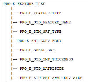
The element tree for the Shell feature is documented in the header file ProSmtShell.h, and is shown in the following figure:
Element Tree for Shell Feature
Image
The elements in this tree are described as follows:
Element ID
Data Type
Description
PRO_E_FEATURE_TYPE
PRO_VALUE_TYPE_INT
Specifies the type of feature. The value of this feature must be PRO_FEAT_DATUM_SURF.
PRO_E_STD_FEATURE_NAME
PRO_VALUE_TYPE_WSTRING
Specifies the name of the feature. The default value is Shell_1.
PRO_E_DTM_SRF_TYPE
PRO_VALUE_TYPE_INT
Specifies the Datum Surface Type using the enumerated type ProSmtDtmSrfType. The value of this feature must be PRO_DTM_SRF_AS_WALL_
SHELL
.
PRO_E_SMT_CONV_BODY
PRO_VALUE_TYPE_SELECTION
Specifies the body to be selected to convert to a sheet metal part.
PRO_E_SHELL_SRF
PRO_VALUE_TYPE_SELECTION
Optional element. Specifies the collection of surfaces to be removed to shell the solid.
PRO_E_STD_SMT_THICKNESS
PRO_ELEM_TYPE_DOUBLE
Specifies the thickness of the wall. It must be positive a number.
PRO_E_STD_MATRLSIDE
PRO_VALUE_TYPE_INT
Specifies the direction of material thickness.
PRO_E_STD_SMT_SWAP_DRV
_SIDE
PRO_VALUE_TYPE_INT
Specifies sheet metal swap sides to switch sides of shelled and driving surfaces.
Driving Surface Feature
The Driving Surface feature converts a solid geometry to sheet metal part. For thin protrusions with constant thickness, use the Driving Surface feature to select a surface as the driving surface and to set the wall thickness.
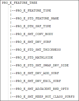
The element tree for the Driving Surface feature is documented in the header file ProSmtDrvSurf.h and is shown in the following figure:
Element Tree for Driving Surface Feature
Image
The elements in this tree are described as follows:
Element ID
Data Type
Description
PRO_E_FEATURE_TYPE
PRO_VALUE_TYPE_INT
Specifies the type of feature. The value of this feature must be PRO_FEAT_DATUM_SURF.
PRO_E_STD_FEATURE_NAME
PRO_VALUE_TYPE_WSTRING
Specifies the name of the feature. The default value is Driving_Surface_1.
PRO_E_DTM_SRF_TYPE
PRO_VALUE_TYPE_INT
Specifies the Datum Surface Type using the enumerated type ProSmtDtmSrfType. The value of this feature must be PRO_DTM_SRF_AS_WALL. For an empty body, the value of this feature must be PRO_DTM_SRF_EMPTY_BODY_CONV.
PRO_E_SMT_CONV_BODY
PRO_VALUE_TYPE_SELECTION
Specifies the body to be selected to be converted to a sheet metal part.
PRO_E_SMT_DRV_SURF
PRO_VALUE_TYPE_SELECTION
Specifies the collection of a solid surface to be used as the driving surface.
PRO_E_STD_SMT_THICKNESS
PRO_ELEM_TYPE_DOUBLE
Specifies the thickness of the wall.
PRO_E_STD_MATRLSIDE
PRO_VALUE_TYPE_INT
Specifies the direction of material thickness.
PRO_E_STD_SMT_SWAP_DRV
_SIDE
PRO_VALUE_TYPE_INT
Specifies sheet metal swap sides to switch sides of driving and selected surfaces.
PRO_E_SMT_DRV_ADD_SURF
Compound
Specifies the additional surface to be used as a driving surface for the sheet metal body part.
PRO_E_SMT_DRV_EXCL_SURF
Compound
Specifies the surfaces to be excluded so that they are not treated as face surfaces in the sheet metal body.
PRO_E_SMT_ADJACENT_RND_OPTS
PRO_VALUE_TYPE_INT
Specifies the adjacent round options and is defined by the enumerated date type ProSmtAdjRndOpts. The valid values follow:
•  PRO_SMT_ADJ_RND_RECREATE—Removes rounds and chamfers and recreates them after the part is converted to a sheet metal part.
•  PRO_SMT_ADJ_RND_REMOVE—Removes the rounded geometry. The resulting geometry is similar to the geometry before the round operation.
•  PRO_SMT_ADJ_RND_IGNORE—Ignores the rounded geometry. The resulting geometry is without the rounded geometry.
PRO_E_SMT_KEEP_NOT_CLASS_SURFS
PRO_VALUE_TYPE_INT
Specifies the keep not classified surfaces and is defined by the enumerated data type ProSmtKeepNotClassSurfsType. The valid values follow:
•  PRO_SMT_IGNORE_NOT_CLASS_SURFS —Ignores surfaces that are not classified as the driving surface, additional surfaces, and excluded surfaces as separate quilts.
•  PRO_SMT_KEEP_NOT_CLASS_SURFS—Keeps surfaces that are not classified as the driving surface, additional surfaces, and excluded surfaces as separate quilts.
Rip Features
Rip features allow you to tear a continuous piece of sheet metal material so that when you unbend a design, it tears along the ripped section. There are four types of rips available:
•  Sketched Rip—Tears the sheet metal part along a sketched path. You can exclude surfaces to protect them from rip.
•  Surface Rip—Cuts out a surface patch from the sheet metal part and in the process removes volume from the part.
•  Edge Rip—Tears the sheet metal part along an edge. You can define edge treatment for the ripped edges.
•  Rip Connect—Tears the sheet metal part between two datum points or vertices or a combination of both.
The four rip types are specified by the enumerated type ProSmtRipType and take the following values:
•  PRO_SMT_RIP_REGULAR—Specifies a Sketched Rip.
•  PRO_SMT_RIP_SURFACE—Specifies a Surface Rip.
•  PRO_SMT_RIP_EDGE—Specifies an Edge Rip.
•  PRO_SMT_RIP_CONNECT—Specifies a Connect Rip.
Sketched Rip Feature
The Sketched Rip feature allows you to tear the sheet metal part along a sketched path.
Feature Element Tree for Sketched Rip Feature
The element tree for a Sketched Rip feature is documented in the header file ProSmtRegularRip.h and has a simple structure. The following figure demonstrates the structure of the feature element tree.
Sketched Rip Element Tree
Image
The elements in this tree are described as follows:
•  PRO_E_FEATURE_TYPE—Specifies the feature type and should be PRO_FEAT_RIP.
•  PRO_E_STD_FEATURE_NAME—Specifies the name of the feature.
•  PRO_E_SMT_RIP_TYPE—Specifies the rip type and should have the value PRO_SMT_RIP_REGULAR.
•  PRO_E_STD_SECTION—Specifies the sketch selected for the rip. You can create a new section or select an internal sketch from the model.
•  PRO_E_SMT_CUT_NORMAL_DIR—Specifies the normal of projection. The projection normal specifies the side of the sheemetal part from where the sketched curve rips the part. The values for this element are as follows:
  PRO_SMT_CUT_DRVSIDE_GREEN—Specifies the normal to the driven surface. This is a direction from the green side to the white side of the sheet metal part. This is the default value.
  PRO_SMT_CUT_DRVSIDE_WHITE—Specifies the normal to the offset surface. This is a direction from the white side to the green side of the sheet metal part.
•  PRO_E_SMT_PROJ_DIR—Specifies the projection direction. It is specified by the enumerated type ProSmtProjDir. The valid values are:
  PRO_SMT_PROJ_DIR_ONE—Specifies the projection to one side. This is the default value.
  PRO_SMT_PROJ_DIR_TWO—Specifies the projection to the opposite side.
  PRO_SMT_PROJ_DIR_BOTH—Specifies the projection to both the sides.
•  PRO_E_STD_MATRLSIDE—Specifies the direction in which the area of the sheet metal part is ripped. It is specified by the enumerated type ProSketchRipMatSide. The valid values are:
  PRO_SKETCHRIP_MATSIDE_ONE—Specifies the rip in one direction.
  PRO_SKETCHRIP_MATSIDE_TWO—Specifies the rip in the opposite direction. This is the default value.
•  PRO_E_STD_SURF_COLLECTION_APPL—Specifies a collection of surfaces that are excluded from the rip operation. This element is optional.
•  PRO_E_BODY—Specifies the body options. Valid only when PRO_E_SMT_FLATTEN_REF_TYPE is PRO_FLATTEN_FORM_ALLSEL
  PRO_E_BODY_USE—must be PRO_BODY_USE_SELECTED
  PRO_E_BODY_SELECT—must contain a single selected body
Surface Rip Feature
The Surface Rip feature allows you to cut out a surface patch from the sheet metal part and in the process removes volume from the part.
Feature Element Tree for Surface Rip Feature
The element tree for a Surface Rip feature is documented in the header file ProSmtSurfaceRip.h and has a simple structure. The following figure demonstrates the structure of the feature element tree.
Surface Rip Element Tree
Image
The elements in this tree are described as follows:
•  PRO_E_FEATURE_TYPE—Specifies the feature type and should be PRO_FEAT_RIP.
•  PRO_E_STD_FEATURE_NAME—Specifies the name of the feature.
•  PRO_E_SMT_RIP_TYPE—Specifies the rip type and should have the value PRO_SMT_RIP_SURFACE.
•  PRO_E_STD_SURF_COLLECTION_APPL—Specifies the collection of surfaces you select to be ripped.
Edge Rip Feature
The Edge Rip feature allows you to tear the sheet metal part along an edge.
Feature Element Tree for Edge Rip Feature
The element tree for a Edge Rip feature is documented in the header file ProSmtEdgeRip.h and has a simple structure. The following figure demonstrates the structure of the feature element tree.
Edge Rip Element Tree
Image
PRO_E_SMT_EDGE_RIP
Image
The elements in this tree are described as follows:
•  PRO_E_FEATURE_TYPE—Specifies the feature type and should be PRO_FEAT_RIP.
•  PRO_E_STD_FEATURE_NAME—Specifies the name of the feature.
•  PRO_E_SMT_RIP_TYPE—Specifies the rip type and should have the value PRO_SMT_RIP_EDGE.
•  PRO_E_SMT_EDGE_RIP_ARRAY—Specifies an array of the element PRO_E_SMT_EDGE_RIP_SET. PRO_E_SMT_EDGE_RIP_SET is a compound element that consists of the following elements:
  PRO_E_SMT_EDGE_RIP_REFERENCES—Specifies an array of the element PRO_E_SMT_EDGE_REFERENCES. PRO_E_SMT_EDGE_REFERENCES is a compound element that consists of the following element:
  PRO_E_STD_CURVE_COLLECTION_APPL—Specifies the chain of edges selected for the rip.
  PRO_E_SMT_EDGE_RIP—Specifies the types and options for the treatment of the ripped edges.
The Element Subtree for PRO_E_SMT_EDGE_RIP
PRO_E_SMT_EDGE_RIP is a compound element that consists of the following elements:
•  PRO_E_SMT_EDGE_RIP_TYPE—Specifies the edge treatment types. It is specified by the enumerated type ProEdgeRipType. The valid types are:
  PRO_EDGE_RIP_OPEN—Rips the sheet metal walls at their point of intersection.
  PRO_EDGE_RIP_BLIND—Rips the sheet metal part with a gap specified by two dimensions.
  PRO_EDGE_RIP_MITER_CUT—Rips the sheet metal part with a gap specified by a single dimension.
  PRO_EDGE_RIP_OVERLAP—Rips the sheet metal part such that one side overlaps the other.
  PRO_EDGE_RIP_PARAM—Rips the sheet metal part by the value specified by the defined SMT_GAP parameter.
•  PRO_E_SMT_EDGE_RIP_FLIP—Specifies whether to flip the overlapping side. This element is available only if the PRO_E_SMT_EDGE_RIP_TYPE has the value PRO_EDGE_RIP_OVERLAP.
•  PRO_E_SMT_EDGE_RIP_ADD_GAP—Specifies whether to a add a gap clearance. This element is applicable only if the element PRO_E_SMT_EDGE_RIP_TYPE has the value PRO_EDGE_RIP_OVERLAP or PRO_EDGE_RIP_PARAM.
•  PRO_E_SMT_EDGE_RIP_CLOSE_CORNER—Specifies if the gap between the bend surfaces of an edge rip must be closed. This element is applicable only if the element PRO_E_SMT_EDGE_RIP_TYPE is set to PRO_EDGE_RIP_OPEN.
•  PRO_E_SMT_EDGE_RIP_DIM_1—Specifies the properties of side 1. This element consists of the following elements:
  PRO_E_SMT_DIMENSION_TYPE—Specifies the dimension type. It is specified by the enumerated type ProEdgeRipDimType. The valid types are:
  PRO_EDGE_RIP_DIM_TYPE_BLIND—Specifies the type PRO_DIM_ENTER.
  PRO_EDGE_RIP_DIM_TYPE_GAP—Specifies the type PRO_DIM_SMT_GAP.
  PRO_EDGE_RIP_DIM_TYPE_PARAM—Specifies the type PRO_DIM_DFLT_EDGE_TREA_WIDTH.
See table Relation Value Types for the descriptions of the above list of value types.
  PRO_E_SMT_DIMENSION_VALUE—Specifies the dimension value for the type selected.
•  PRO_E_SMT_EDGE_RIP_DIM_2—Specifies the properties of side 2. This compound element consists of the same elements as the element PRO_E_SMT_EDGE_RIP_DIM_1.
Rip Connect Feature
The Rip Connect feature allows you to tear the sheet metal part between two datum points or vertices or a combination of both. A rip connect endpoint must be either a datum point, or a vertex and must lie at the end of an edge rip or on the part border.
The element tree for the Rip Connect feature is documented in the header file ProSmtConnectRip.h and is as shown in the following figure:
Element Tree for Rip Connect Feature
Image
The elements in this tree are described as follows:
Element ID
Data Type
Description
PRO_E_FEATURE_TYPE
PRO_VALUE_TYPE_INT
Specifies the type of feature. The value of this feature must be PRO_FEAT_RIP.
PRO_E_STD_FEATURE_NAME
PRO_VALUE_TYPE_WSTRING
Specifies the name of the feature. The default value is Rip_Connect_1.
PRO_E_SMT_RIP_TYPE
PRO_VALUE_TYPE_INT
Specifies the rip type. The valid value for this element is PRO_SMT_RIP_CONNECT.
PRO_E_SMT_RIP_CONNECT_COMP
Compound
Specifies a compound element.
PRO_E_SMT_RIP_CONNECT_SETS
Array
Specifies an array of rip connect sets.
PRO_E_SMT_RIP_CONNECT_SET
Compound
Specifies a compound element of reference points and gap parameters.
PRO_E_SMT_RIP_CONN_REFS
Array
Specifies an array element containing the starting and end point of the rip connect feature. You can specify up to two elements in this array.
PRO_E_SMT_RIP_CONN_REF
Compound
Specifies a compound element of vertex or datum points.
PRO_E_SMT_RIP_CONN_END
PRO_VALUE_TYPE_SELECTION
Specifies a vertex or datum point to define the start or end of the rip. This vertex or datum point must be placed on the edge or the border of a sheet metal part.
PRO_E_SMT_RIP_CONN_GAP
_COMP
Compound
Specifies a compound element of gap parameters.
PRO_E_SMT_RIP_CONN_ADD
_GAP
PRO_VALUE_TYPE_BOOLEAN
Specifies if a gap clearance should be added to the selected set of the rip connect. The valid values are TRUE or FALSE.
PRO_E_SMT_RIP_CONN_GAP
_VAL
PRO_VALUE_TYPE_DOUBLE
Specifies the gap value.
Creating a Rip Feature
Function Introduced
Use the function ProFeatureCreate() to create a specific Rip feature based on the element tree definition. For more information about ProFeatureCreate(), refer the Overview of Feature Creation section in the Element Trees: Principles of Feature Creation section.
Redefining a Rip Feature
Function Introduced
Use the function ProFeatureRedefine() to redefine a Rip feature based on the changes made in the element tree. For more information about ProFeatureRedefine(), refer the Feature Redefine section in the Element Trees: Principles of Feature Creation section.
Accessing a Rip Feature
Function Introduced
Use the function ProFeatureElemtreeExtract() to retrieve the element tree description of the Rip feature. For more information about ProFeatureElemtreeExtract(), refer the Feature Inquiry section in the Element Trees: Principles of Feature Creation section.
Corner Relief Feature
Corner relief can be added at each intersection of a pair of bends. When you add relief, sheet metal sections are removed from the model.
The element tree for the Corner Relief feature is documented in the header file ProSmtCornerRelief.h and is shown in the following figure:
Element Tree for Corner Relief Feature
Image
The elements in this tree are described as follows:
Element ID
Data Type
Description
PRO_E_STD_FEATURE_NAME
PRO_VALUE_TYPE_WSTRING
Specifies the name of the feature. The default value is Corner_Relief_1.
PRO_E_CORNER_RELIEFS
Compound
This compound element defines the corner relief sets.
PRO_E_CORNER_RELIEFS_CR_STATE
PRO_VALUE_TYPE_INT
Specifies the corner relief state using the enumerated data type ProCrnRelCrState and has the values:
•  PRO_CRN_REL_CR_IN
_FORMED
—Creates corner relief geometry only when the corner bends are in formed state.
•  PRO_CRN_REL_CR_IN_UNBEND_ONLY—Creates corner relief geometry only when the corner bends are in unbend state.
PRO_E_CORNER_RELIEFS_ARR
Array
An array element of corner relief sets.
PRO_E_CORNER_RELIEF_SET
Compound
This compound element contains a corner relief set.
PRO_E_CORNER_RELIEF_REF_ARR
Array
An array element that contains the corners selected in this set.
PRO_E_CORNER_RELIEF_REF_SET
Compound
A set of elements that defines a selected corner.
PRO_E_CORNER_RELIEF_REF_TYPE
PRO_VALUE_TYPE_INT
Specifies the type of corner relief using the enumerated data type ProCrnRelRefType. The valid values for this element are:
•  PRO_CRN_REL_3_SURFACES—Corner relief must be applied to the specified corners in the model.
•  PRO_CRN_REL_ALL—Corner relief must be applied to all the corners in the model.
PRO_E_CORNER_RELIEF_REF_FLAT
PRO_VALUE_TYPE_SELECTION
Specifies selection of a flat surface that is used to locate the corner.
PRO_E_CORNER_RELIEF_REF_BND_1
PRO_VALUE_TYPE_SELECTION
Specifies selection of a first cylindrical surface that is used to locate the corner.
PRO_E_CORNER_RELIEF_REF_BND_2
PRO_VALUE_TYPE_SELECTION
Specifies selection of a second cylindrical surface that is used to locate the corner.
PRO_E_CORNER_RELIEF_DEFINE
Compound
A corner relief compound element.
Refer to the section Corner Relief Options for more details on this element and subsequent child elements.
PRO_E_BODY
Compound
Specifies the body options. The valid values are:
•  PRO_E_BODY_USEPRO_BODY_USE_SELECTED
•  PRO_E_BODY_SELECT—must contain a single selected body
Corner Relief Options
The compound element PRO_E_CORNER_RELIEF_DEFINE defines the options and values for a corner relief feature.
Element Tree for Corner Relief Feature Options
Image
The elements of PRO_E_CORNER_RELIEF_DEFINE are described as follows:
Element ID
Data Type
Description
PRO_E_CORNER_RELIEF_DEFINE
Compound
A corner relief compound element.
PRO_E_SMT_CORNER_RELIEF
Compound
This compound element defines the corner relief properties.
PRO_E_SMT_CORNER_RELIEF_TYPE
PRO_VALUE_TYPE_INT
Specifies the type of corner relief using the enumerated data type ProCornerRelType and has the following values:
•  PRO_CORNER_RELIEF_V_NOTCH—Adds a V notch shape cut at the corners.
•  PRO_CORNER_RELIEF_CIRCULAR—Adds a circular shape relief at the corners with a radius dimension.
•  PRO_CORNER_RELIEF_RECTANGULAR—Adds a rectangular relief at the corners with a specified width and depth.
•  PRO_CORNER_RELIEF_OBROUND—Adds an obround relief at the corners with a specified diameter and depth.
•  PRO_CORNER_RELIEF_NO—Does not add relief and generates square corners.
•  PRO_CORNER_RELIEF_PARAM—Adds the corner relief as set by the SMT_DFLT_CRNR_REL
_TYPE
parameter in Creo Parametric.
PRO_E_SMT_CORNER_RELIEF_WIDTH
Compound
This compound element defines the width type and width value for corner relief.
PRO_E_SMT_CORNER_RELIEF_WIDTH_TYPE
PRO_VALUE_TYPE_INT
Specifies the type of width for the corner relief using the enumerated data type ProSmdRelType and uses one of the values listed in Relation Value Types
PRO_E_SMT_CORNER_RELIEF_WIDTH_VAL
PRO_VALUE_TYPE_DOUBLE
Specifies the value of width for the corner relief.
PRO_E_SMT_CORNER_RELIEF_DEPTH
Compound
This compound element defines the depth type and depth value for corner relief.
PRO_E_SMT_CORNER_RELIEF_DEPTH_TYPE
PRO_VALUE_TYPE_INT
Specifies the type of depth for the corner relief using the enumerated data type ProCornerRlfDepthType and uses one of the values listed in Relation Value Types
PRO_E_SMT_CORNER_RELIEF_DEPTH_VAL
PRO_VALUE_TYPE_DOUBLE
Specifies the value of depth value for the corner relief.
PRO_E_SMT_CORNER_RELIEF_ROTATE
Compound
This compound element defines the rotation parameters for corner relief and is applicable only if PRO_E_SMT_CORNER_RELIEF_TYPE value is PRO_CORNER_RELIEF_OBROUND or PRO_CORNER_RELIEF_RECTANGULAR.
PRO_E_SMT_CORNER_RELIEF_ROTATE_ADD
PRO_VALUE_TYPE_INT
Specifies if rotation should be added to the relief placement. The valid values for this element are:
•  PRO_B_TRUE
•  PRO_B_FALSE
PRO_E_SMT_CORNER_RELIEF_ROTATE_VAL
PRO_VALUE_TYPE_DOUBLE
Specifies the value of rotation.
PRO_E_SMT_CORNER_RELIEF_OFFSET
Compound
This compound element defines the offset parameters for corner relief and is applicable only if PRO_E_SMT_CORNER_RELIEF_TYPE value is PRO_CORNER_RELIEF_CIRCULAR, PRO_CORNER_RELIEF_OBROUND or PRO_CORNER_RELIEF_RECTANGULAR.
PRO_E_SMT_CORNER_RELIEF_OFFSET_ADD
PRO_VALUE_TYPE_INT
Specifies if offset should be added to the relief placement. The valid values for this element are:
•  PRO_B_TRUE
•  PRO_B_FALSE
PRO_E_SMT_CORNER_RELIEF_OFFSET_VAL
PRO_VALUE_TYPE_DOUBLE
Specifies the offset value.
PRO_E_CORNER_RELIEFS_DIM_SCHEME
PRO_VALUE_TYPE_INT
Specifies the dimension scheme using the enumerated data type ProCrnRelDimRefType and has the values:
•  PRO_CRN_REL_DIM_REF
_BEND_AXES_XSECTION

—Places the relief at the point where the bend edges intersect.
•  PRO_CRN_REL_DIM
_REF_CORNER_VERTEX

—Places the relief at the point where the bend lines intersect.
Editing Corner Relief Feature
The Edit Corner Relief feature removes or edits multiple corner relief design objects in your model. When you edit corner reliefs, you can change the width and depth of different types of reliefs and you can set bounding surfaces to remove. You can edit corner reliefs to no relief or to any one of the types of corner reliefs.
The element tree for the Edit Corner Relief feature is documented in the header file ProSmtEditCornerRelief.h and is shown in the following figure:
Image
The elements in this tree are described as follows:
Element ID
Data Type
Description
PRO_E_FEATURE_TYPE
PRO_VALUE_TYPE_INT
Mandatory element. Specifies the type of the feature. The valid value for this element is PRO_FEAT_EDIT_CORNER_RELIEF.
PRO_E_STD_FEATURE_NAME
PRO_VALUE_TYPE_WSTRING
Specifies the name of the feature. The default value is Edit_Corner_Relief_1.
PRO_E_EDIT_CORNER_RELIEF
Compound
This compound element defines the options and sets the values for editing corner reliefs.
PRO_E_EDIT_CORNER_RELIEF_SEL_OPT
PRO_VALUE_TYPE_INT
Specifies the corner relief state using the enumerated data type ProCrnRelCrState. It has the following valid values:
•  PRO_CRN_REL_CR_IN_FORMED—Creates corner relief geometry only when the corner bends are in formed state.
•  PRO_CRN_REL_CR_IN_UNBEND_ONLY—Creates corner relief geometry only when the corner bends are in unbend state.
PRO_E_CORNER_RELIEF_DEFINE
Compound
A corner relief compound element.
Refer to the section Corner Relief Options for more details on this element and subsequent child elements.
PRO_E_BODY
Compound
Specifies the body options. The valid values are:
•  PRO_E_BODY_USEPRO_BODY_USE_SELECTED
•  PRO_E_BODY_SELECT—must contain a single selected body
Editing Corner Seams
The Edit Corner Seam feature enables you to remove or edit multiple corner seam design objects in your model.
The element tree for the Edit Corner Seam feature is documented in the header file ProSmtEditCornerSeam.h and is as shown in the following figure:
Feature Element Tree for Edit Corner Seam Feature
Image
The elements in this tree are described as follows:
Element ID
Data Type
Description
PRO_E_FEATURE_TYPE
PRO_VALUE_TYPE_INT
Mandatory element. Specifies the type of the feature. The valid value for this element is PRO_FEAT_EDIT_CORNER_SEAM.
PRO_E_STD_FEATURE_NAME
PRO_VALUE_TYPE_WSTRING
Mandatory element. Specifies the name of the feature. The default value is Edit_Corner_Seam_1.
PRO_E_EDIT_CORNER_SEAM
Compound
Mandatory element. This compound element defines the options and sets the values for editing corner seams.
PRO_E_EDIT_CORNER_SEAM_SEL_MODE
PRO_VALUE_TYPE_INT
Mandatory element. Specifies the mode for selecting corner seams. The valid values are:
•  PRO_SMT_RECOGNITION_MANUAL_SEL—Specifies manual selection of corner seams to edit.
•  PRO_SMT_RECOGNITION_AUTO_SEL—Specifies automatic selection of corner seams to edit.
PRO_E_EDIT_CORNER_SEAM_GEOMS
Multi Collector
This element is mandatory when the selection mode is set to PRO_SMT_RECOGNITION_MANUAL_SEL.
Specifies the selection of geometry for corner seams.
PRO_E_REMOVE_CORNER_SEAM
PRO_VALUE_TYPE_BOOLEAN
Specifies that the corner seam must be removed.
PRO_E_EDIT_CORNER_SEAM_SHAPE
Compound
This element is mandatory when the element PRO_E_REMOVE_CORNER_SEAM is set to false.
This compound element defines the options and sets the values for corner seam edges.
PRO_E_EDIT_BEND_RCR_CRNR
PRO_VALUE_BOOLEAN
Specifies if the corner reliefs must be automatically changed to V notch corner type.
PRO_E_CRNR_SEAM_CR_RND_CHMF
PRO_VALUE_TYPE_INT
Mandatory element. Specifies if the rounds and chamfers must be recreated after the corner seams are edited. The input to the element are the values defined by the enumerated data type ProEditBendCrRndChmfOpt. The valid values are:
•  PRO_ED_CR_CRNR_SEAM_RND_CHMF— The rounds and chamfers are recreated.
•  PRO_ED_NO_CR_CRNR_SEAM_RND_CHMF— The rounds and chamfers are not recreated.
PRO_E_SMT_EDGE_RIP_TYPE
PRO_VALUE_TYPE_INT
Specifies the type of corner seam using the enumerated data type ProEdgeRipType. The valid values are:
•  PRO_EDGE_RIP_OPEN—Edits the corner seam at the intersection point of edges.
•  PRO_EDGE_RIP_BLIND—Edits the corner seam with a gap specified by two dimensions.
•  PRO_EDGE_RIP_MITER_CUT—Edits the corner seam with a gap specified by a single dimension.
•  PRO_EDGE_RIP_OVERLAP—Edits the corner seam such that one edge overlaps the other.
PRO_E_SMT_EDGE_RIP_ADD_GAP
PRO_VALUE_TYPE_BOOLEAN
Specifies whether to add a gap clearance. This element is applicable only if the element PRO_E_SMT_EDGE_RIP_TYPE is set to PRO_EDGE_RIP_MITER_CUT or PRO_EDGE_RIP_OVERLAP.
PRO_E_SMT_EDGE_RIP_CLOSE_CORNER
PRO_VALUE_TYPE_BOOLEAN
Specifies if the gap between the bend surfaces of a corner relief must be closed. This element is applicable only if the element PRO_E_SMT_EDGE_RIP_TYPE is set to PRO_EDGE_RIP_OPEN.
PRO_E_SMT_EDGE_RIP_DIM_1
Compound
This element is mandatory when the element PRO_E_SMT_EDGE_RIP_TYPE is set to PRO_EDGE_RIP_BLIND.
Specifies a compound element that defines the properties of side 1.
PRO_E_SMT_DIMENSION_TYPE
PRO_VALUE_TYPE_INT
Specifies the dimension type. For PRO_EDGE_RIP_DIM_TYPE_BLIND dimension type, the relation value is set to PRO_ DIM_ENTER.
PRO_E_SMT_DIMENSION_VALUE
PRO_VALUE_TYPE_DOUBLE
Specifies the dimension value for side 1.
PRO_E_SMT_EDGE_RIP_DIM_2
Compound
This element is mandatory when the element PRO_E_SMT_EDGE_RIP_TYPE is set to PRO_EDGE_RIP_BLIND.
Specifies a compound element that defines the properties of side 2.
PRO_E_SMT_DIMENSION_TYPE
PRO_VALUE_TYPE_INT
Specifies the dimension type. For PRO_EDGE_RIP_DIM_TYPE_BLIND dimension type, the relation value is set to PRO_ DIM_ENTER.
PRO_E_SMT_DIMENSION_VALUE
PRO_VALUE_TYPE_DOUBLE
Specifies the dimension value for side 2.
PRO_E_SMT_EDGE_RIP_GAP
Compound
This element is mandatory when the element PRO_E_SMT_EDGE_RIP_TYPE is set to PRO_EDGE_RIP_MITER_CUT or PRO_E_SMT_EDGE_RIP_ADD_GAP is set to true.
Specifies the properties for the gap.
PRO_E_SMT_DIMENSION_TYPE
PRO_VALUE_TYPE_INT
Specifies the gap type. For PRO_EDGE_RIP_MITER_CUT and PRO_EDGE_RIP_OVERLAP dimension types the relation value is set to PRO_ DIM_ENTER.
PRO_E_SMT_DIMENSION_VALUE
PRO_VALUE_TYPE_DOUBLE
Specifies the value for the gap.
PRO_E_SMT_EDGE_RIP_FLIP
PRO_VALUE_TYPE_BOOLEAN
Specifies if the side of corner seam that overlaps must be flipped.
PRO_E_EDIT_CORNER_SEAM_TABLE
Array
Specifies an array element that defines the options to remove the corner seam.
PRO_E_CORNER_SEAM_RMV_SETTINGS
Compound
Specifies a compound element that defines the options to remove the corner seam.
PRO_E_EDIT_CORNER_SEAM_RMV_REFS
Compound
Specifies a compound element that defines the corner reference geometry to which the seam is attached. The surface should be planar or two cylinders.
PRO_E_CORNER_SEAM_RMV_FLAT
PRO_VALUE_TYPE_SELECTION
Specifies a flat surface.
PRO_E_CORNER_SEAM_RMV_BEND_1
PRO_VALUE_TYPE_SELECTION
Specifies the first bend surface.
PRO_E_CORNER_SEAM_RMV_BEND_2
PRO_VALUE_TYPE_SELECTION
Specifies the second bend surface.
PRO_E_CORNER_SEAM_BOUNDARIES
Multi Collector
Specifies collection of bounding surfaces.
PRO_E_CORNER_SEAM_RMV_SIDE_1
Compound
Specifies a compound element that defines the properties of side 1.
PRO_E_CORNER_SEAM_RMV_DEFAULT
PRO_VALUE_TYPE_BOOLEAN
Specifies the default option to remove the corner seam for side 1.
PRO_E_EDIT_CORNER_SEM_RMV_METHOD
PRO_VALUE_TYPE_INT
Specifies the method to remove the corner seam for side 1. The valid values are specified using the enumerated data type ProEditCornerSeamRemoveType:
•  PRO_CORNER_SEAM_REMOVE_TANGENT—Extends or trims the bounding surface making it a planar surface tangent to original surface.
•  PRO_CORNER_SEAM_REMOVE_SAME—Extends or trims the bounding surface by continuing past its original boundaries and keeping the same type of surface.
•  PRO_CORNER_SEAM_REMOVE_PARALLEL—Extends or trims the bounding surface parallel to the bend axis.
•  PRO_CORNER_SEAM_REMOVE_COMMON_VERTEX—Extends or trims the bounding surface normal to the corner.
•  PRO_CORNER_SEAM_REMOVE_NORMAL—Finds the common vertex for intersection of both bounding surfaces.
PRO_E_CORNER_SEAM_RMV_SIDE_2
Compound
Specifies a compound element that defines the properties of side 2.
PRO_E_CORNER_SEAM_RMV_DEFAULT
PRO_VALUE_TYPE_BOOLEAN
Specifies the default option to remove the corner seam for side 2.
PRO_E_EDIT_CORNER_SEM_RMV_METHOD
PRO_VALUE_TYPE_INT
Specifies the method to remove the corner seam for side 2 using the enumerated data type ProEditCornerSeamRemoveType.
PRO_E_BODY
Compound
Specifies the body options. Mandatory when Selection Type is PRO_SMT_RECOGNITION_AUTO_SEL. The valid values are:
•  PRO_E_BODY_USE—must be PRO_BODY_USE_SELECTED
•  PRO_E_BODY_SELECT—must contain a single selected body
Bend Feature
The Bend feature allows you to bend the sheet metal in different ways using the bend line or an edge or a curve and by defining specific radius and angle.
The element tree for the Bend feature is documented in the header file ProSmtBend.h and is as shown in the following figure:
Feature Element Tree for Bend Feature
Image
The elements in this tree are described as follows:
Element ID
Data Type
Description
PRO_E_FEATURE_TYPE
PRO_VALUE_TYPE_INT
Mandatory element. Specifies the type of the feature. The valid value for this element is PRO_FEAT_BEND.
PRO_E_STD_FEATURE_NAME
PRO_VALUE_TYPE_WSTRING
Specifies the name of the feature. The default value is Bend_1.
PRO_E_SMT_BEND_FORM
PRO_VALUE_TYPE_INT
Specifies the type of bend using the enumerated data type ProBendForm. The valid values for this element are:
•  PRO_SMT_BEND_FORM_ANGLE—Specifies an angled type of bend.
•  PRO_SMT_BEND_FORM
_ROLL
—Specifies a rolled type of bend.
PRO_E_SMT_BEND_LINE
Compound
This compound element defines the bend line properties. For more information, see the section Bend Line Elements.
PRO_E_SMT_BEND_FIXED
_SIDE
PRO_VALUE_TYPE_INT
Specifies the fixed side of the bend using the enumerated data type ProBendSide. The valid values for this element are:
•  PRO_SMT_BEND_SIDE
_ONE
—Specifies first side as the fixed side.
•  PRO_SMT_BEND_SIDE
_TWO
—Specifies the second side as the fixed side.
PRO_E_SMT_BEND_LOCATION
PRO_VALUE_TYPE_INT
Specifies the location of the bend in relation to the bend line, using the enumerated data type ProBendSide. The valid values for this element are:
•  PRO_SMT_BEND_SIDE
_ONE
—Specifies a bend up to the bend line.
•  PRO_SMT_BEND_SIDE
_TWO
—Specifies a bend up to the other side of the bend line.
•  PRO_SMT_BEND_BOTH
_SIDES
—Specifies a bend centered on both sides of the bend line.
PRO_E_SMT_BEND_DIRECTION
PRO_VALUE_TYPE_INT
Specifies the direction of the bend using the enumerated data type ProBendSide. The valid values for this element are:
•  PRO_SMT_BEND_SIDE
_ONE
—Specifies the bend direction normal to the selected surface.
•  PRO_SMT_BEND_SIDE
_TWO
—Flips the bend direction.
PRO_E_SMT_BEND_ANGLE
Compound
This compound element and its sub-elements are available when the element PRO_E_SMT_BEND_FORM has its value as PRO_SMT_BEND_FORM_ANGLE.
The compound element defines the bend angle.
PRO_E_SMT_BEND_ANGLE_TYPE
PRO_VALUE_TYPE_INT
Specifies the bend angle type using the enumerated data type ProBendAngleType. The valid values for this element are:
•  PRO_SMT_BEND_ANGLE_INTERNAL—Specifies the resulting internal bend angle.
•  PRO_SMT_BEND_ANGLE_EXTERNAL—Specifies the bend angle deflection from straight.
PRO_E_SMT_BEND_ANGLE_VALUE
PRO_VALUE_TYPE_DOUBLE
Specifies the value of the bend angle.
PRO_E_SMT_BEND_TRANS
_FLIP
PRO_VALUE_TYPE_INT
Flips the direction where the bend cylinder will be created along the bend transition line using the enumerated data type ProBendSide. The valid values for this element are:
•  PRO_SMT_BEND_SIDE
_ONE
— Creates the cylinder along the first line of the transition.
•  PRO_SMT_BEND_SIDE
_TWO
—Creates the cylinder along the second line of the transition.
Note
The transition flip element is available only if there is one transition set in the feature.
PRO_E_SMT_BEND_TRANS_AREAS
Array
An array element of bend transition lines that defines the bend transition area.
PRO_E_SMT_BEND_TRANS_SET
Compound
This compound element defines the bend transition lines.
PRO_E_STD_SECTION
Compound
This compound element specifies a sketched section for the bend line. For more information on how to create features that contain sketched sections, refer to the section Creating Features Containing Sections.
PRO_E_SMT_FILLETS
Compound
This compound element defines the bend properties of the sheet metal wall and the value of bend radius.
PRO_E_SMT_FILLETS_SIDE
PRO_VALUE_TYPE_INT
Specifies the fillet side. The valid values are:
•  PRO_BEND_RAD_OUTSIDE—Applies the bend radius to the outer surface of the bend.
•  PRO_BEND_RAD_INSIDE—Applies the bend radius to the inner surface of the bend.
•  PRO_BEND_RAD_PARAMETER—Applies the bend radius at the dimension location set by the SMT_DFLT_RADIUS_SIDE parameter in Creo Parametric.
PRO_E_SMT_FILLETS_VALUE
PRO_VALUE_TYPE_DOUBLE
Specifies the value of the bend radius.
PRO_E_SMT_BEND_RELIEF
Compound
This compound element defines the bend relief at the edges. For more information see the section Bend Relief Elements.
PRO_E_SMT_DEV_LEN_CALCULATION
Compound
This compound element defines the method used to calculate the Developed Length dimensions for the bends. For more information see the section The Element Subtree for Length Calculation
Bend Line Elements
This compound element PRO_E_SMT_BEND_LINE defines the bend line, its properties and references for sheet metal bends.
Image
The elements of PRO_E_SMT_BEND_LINE are described as follows:
Element ID
Data Type
Description
PRO_E_SMT_BEND_LINE_TYPE
PRO_VALUE_TYPE_INT
Specifies the type of bend using the enumerated data type ProBendLineType. The valid values for this element are:
•  PRO_SMT_BEND_LINE
_NOT_DEFINED
—Specifies an undefined bend line.
•  PRO_SMT_BEND_LINE
_SKETCH
Specifies a user defined bend line.
•  PRO_SMT_BEND_LINE
_CURVE
—Specifies a linear chain to be used as the bend line.
•  PRO_SMT_BEND_LINE_INTERNAL_LINE—Specifies the bend line that will be created based on the compound element PRO_E_SMT_BEND_LINE
_INTERNAL
.
PRO_E_SMT_BEND_REF_SURFACE
PRO_VALUE_TYPE_SELECTION
This element is available when the value of element PRO_E_SMT_BEND_LINE_TYPE is PRO_SMT_BEND_LINE_INTERNAL_LINE or PRO_SMT_BEND_LINE_
SKETCH
.
Specifies the surface to be bent. This is the surface on which the bend line is set.
PRO_E_STD_SECTION
Compound
This compound element and its sub-elements are available only if the element PRO_E_SMT_BEND_LINE_TYPE has its value as PRO_SMT_BEND_LINE
_SKETCH
.
The compound element specifies a sketched section for the bend line. For more information on how to create features that contain sketched sections, refer to the section Creating Features Containing Sections on page 1147.
PRO_E_SMT_BEND_CURVE
Compound
This element and its sub-elements are available when the element PRO_E_SMT_BEND_LINE_TYPE has its value as PRO_SMT_BEND_LINE_CURVE.
This compound element defines the curve references and bend curve offset value.
PRO_E_STD_CURVE_COLLECTION_APPL
PRO_VALUE_TYPE_POINTER
Specifies a surface edge or a curve that defines the bend line.
PRO_E_SMT_BEND_CURVE_
USE_OFFSET
PRO_VALUE_TYPE_INT
Specifies whether to offset the bend curve from the selected reference. The valid values for this element are:
•  PRO_B_TRUE
•  PRO_B_FALSE
PRO_E_SMT_BEND_CURVE
_OFFSET_VALUE
PRO_VALUE_TYPE_DOUBLE
Specifies the offset value for the bend curve.
PRO_E_SMT_BEND_LINE_INTERNAL
Compound
This element and its sub-elements are available when the element PRO_E_SMT_BEND_LINE_TYPE has its value as PRO_SMT_BEND_LINE_INTERNAL_LINE.
The compound element defines the bend line reference ends, offsets and offset values.
PRO_E_SMT_BEND_LINE_REF
_END1
PRO_VALUE_TYPE_SELECTION
Specifies a vertex or an edge as the placement reference for the first end of the bend line.
PRO_E_SMT_BEND_LINE_REF
_END2
PRO_VALUE_TYPE_SELECTION
Specifies a vertex or an edge as the placement reference for the second end of the bend line.
PRO_E_SMT_BEND_LINE_REF
_OFFSET1
PRO_VALUE_TYPE_SELECTION
This element is available when you choose an edge reference in the element PRO_E_SMT_BEND_LINE_
REF_END1
.
Specifies an edge as the offset reference for the first end of the bend line.
PRO_E_SMT_BEND_LINE_REF
_OFFSET2
PRO_VALUE_TYPE_SELECTION
This element is available when you choose an edge reference in the element PRO_E_SMT_BEND_LINE_
REF_END2
.
Specifies an edge as the offset reference for the second end of the bend line.
PRO_E_SMT_BEND_LINE_REF
_OFFSET1_VALUE
PRO_VALUE_TYPE_DOUBLE
This element is available when you choose an edge reference in the element PRO_E_SMT_BEND_LINE
_REF_END1
.
Specifies the offset value from the first end of the bend line.
PRO_E_SMT_BEND_LINE_REF
_OFFSET2_VALUE
PRO_VALUE_TYPE_DOUBLE
This element is available when you choose an edge reference in the element PRO_E_SMT_BEND_LINE
_REF_END2
.
Specifies the offset value from the second end of the bend line.
Bend Relief Elements
The compound element PRO_E_SMT_BEND_RELIEF defines the bend relief elements. The relief can be specified differently on each side of the bend.
Image
The two main elements of PRO_E_SMT_BEND_RELIEF are:
•  PRO_E_SMT_BEND_RELIEF_SIDE1—This compound element specifies the bend relief applied to the first side of the end of the bend.
•  PRO_E_SMT_BEND_RELIEF_SIDE2—This compound element specifies the bend relief applied to the second side of the end of the bend.
The following elements are common to the both the compound elements:
Element ID
Data Type
Description
PRO_E_BEND_RELIEF_TYPE
PRO_VALUE_TYPE_INT
Specifies the relief type using the enumerated data type ProBendRlfType. The valid values for this element are:
•  PRO_BEND_RLF_NONE— Specifies no relief.
•  PRO_BEND_RLF_RIP— Specifies ripping of the material.
•  PRO_BEND_RLF_STRETCH— Specifies stretching of the material for bend relief.
•  PRO_BEND_RLF_RECTANGULAR— Specifies adding a rectangular relief.
•  PRO_BEND_RLF_OBROUND— Specifies adding an obround relief.
•  PRO_BEND_RLF_PARAM— Specifies relief type set by the part parameter SMT_DFLT_BEND_REL_TYPE.
PRO_E_BEND_RELIEF_WIDTH
PRO_VALUE_TYPE_DOUBLE
Specifies the relief width and is applicable only if the value of PRO_E_BEND_RELIEF_TYPE is PRO_BEND_RLF_RECTANGULAR, PRO_BEND_RLF_STRETCH or PRO_BEND_RLF_OBROUND.
PRO_E_BEND_RELIEF_DEPTH_TYPE
PRO_VALUE_TYPE_INT
Specifies the type of depth relief. The valid values for this element are defined in the enumerated type ProBendRlfDepthType and are as follows:
•  PRO_BEND_RLF_DEPTH_NOT_USED— Specifies that the depth for the relief is not used.
•  PRO_BEND_RLF_DEPTH_BLIND— Creates a relief through the geometry as per the specified value.
•  PRO_BEND_RLF_DEPTH_UP_TO_BEND— Creates a relief up to the bend.
•  PRO_BEND_RLF_DEPTH_TAN_TO_BEND— Creates a relief tangential to the bend. PRO_BEND_RLF_DEPTH_TAN_TO_BEND is applicable only when relief type is set to PRO_BEND_RLF _OBROUND.
•  PRO_BEND_RLF_DEPTH_TYPE_PARAM— Specifies the depth type of the relief at the dimension location and is set by part parameter SMT_DFLT_BEND_REL_DEPTH_TYPE.
This element decides the visibility of the bend relief depth element PRO_E_BEND_RELIEF_DEPTH. If PRO_E_BEND_RELIEF_DEPTH_TYPE is set to PRO_BEND_RLF_DEPTH_BLIND or PRO_BEND_RLF_DEPTH_TYPE_PARAM and the part parameter SMT_DFLT_BEND_REL_DEPTH
_TYPE
is set to Blind, then the existing element PRO_E_BEND_RELIEF_DEPTH is used.
PTC recommends that you define the element PRO_E_BEND_RELIEF_DEPTH_TYPE explicitly for all Creo TOOLKIT applications. If the element PRO_E_BEND_RELIEF_DEPTH_TYPE is not defined, the default value is used. The default value from Creo Parametric 1.0 onwards, depends on the part parameter SMT_DFLT_BEND_REL_DEPTH
_TYPE
and the configuration option SMT_DRIVE_TOOLS_BY_PARAMETERS.
If the value of the configuration option SMT_DRIVE_TOOLS_BY_PARAMETERS is set to No, then the default value is the last bend relief type, as selected in Creo Parametric during the creation of the new feature. For the Pro/TOOLKIT applications prior to Creo Parametric 1.0, if the default value is not Blind, then the element PRO_E_BEND_RELIEF_DEPTH_TYPE is not used. For such cases, set the PRO_E_BEND_RELIEF_DEPTH_TYPE to PRO_BEND_RLF_DEPTH_BLIND.
PRO_E_BEND_RELIEF_DEPTH
PRO_VALUE_TYPE_DOUBLE
Specifies the relief depth and is applicable only if the value of PRO_E_BEND_RELIEF_TYPE is PRO_BEND_RLF_RECTANGULAR or PRO_BEND_RLF_OBROUND.
PRO_E_BEND_RELIEF_LENGTH_TYPE
PRO_VALUE_TYPE_INT
Specifies the type of the relief length and is defined by the enumerated data type ProBendRlfLengthType. The valid values follow:
•  PRO_BEND_RLF_LENGTH_NOT_USED
•  PRO_BEND_RLF_LENGTH_BLIND—Creates the bend reliefs with a length of the specified value.
•  PRO_BEND_RLF_LENGTH_TO_NEXT—Creates the bend reliefs with a length to the next surface.
•  PRO_BEND_RLF_LENGTH_THROUGH_ALL—Creates the bend reliefs through all surfaces.
•  PRO_BEND_RLF_LENGTH_TYPE_PARAM—Uses the SMT_DFLT_BEND_REL_LENGTH_TYPE parameter value.
PRO_E_BEND_RELIEF_LENGTH
PRO_VALUE_TYPE_DOUBLE
Specifies the value of the relief length.
PRO_E_BEND_RELIEF_ANGLE
PRO_VALUE_TYPE_DOUBLE
Specifies the relief angle and is applicable only if the value of PRO_E_BEND_RELIEF_TYPE is PRO_BEND_RLF_STRETCH.
Editing Bend Reliefs
The Edit Bend Relief feature enables you to edit bend reliefs in existing bends.
The element tree for the Edit Bend Relief feature is documented in the header file ProSmtEditBendRelief.h and is shown in the following figure:
Feature Element Tree for Edit Bend Relief Feature
Image
The elements in this tree are described as follows:
Element ID
Data Type
Description
PRO_E_FEATURE_TYPE
PRO_VALUE_TYPE_INT
Mandatory element. Specifies the type of feature. The value of this feature must be PRO_FEAT_EDIT_BEND_RELIEF.
PRO_E_STD_FEATURE_NAME
PRO_VALUE_TYPE_WSTRING
Mandatory element. Specifies the name of the feature. The default value is EDIT_BEND_RELIEF_1.
PPRO_E_EDIT_BEND_RELIEF
Compound
Mandatory element. This compound element defines the options and sets the values for editing a bend relief.
PRO_E_EDIT_BEND_RELIEF_SEL_MODE
PRO_VALUE_TYPE_INT
Mandatory element. Specifies the mode for selecting bend reliefs. The valid values are:
•  PRO_SMT_RECOGNITION_MANUAL_SEL—Specifies manual selection of bend reliefs to edit.
•  PRO_SMT_RECOGNITION_AUTO_SEL—Specifies automatic selection of bend reliefs to edit.
PRO_E_EDIT_BEND_RELIEF_GEOMS
Multi Collector
This element is mandatory when the selection mode is set to PRO_SMT_RECOGNITION_MANUAL_SEL. Specifies the selection of geometry for bend reliefs.
You can select valid bend relief design objects, geometry of recognizable bend reliefs, or surfaces of bends for which bend reliefs can be edited. You can also select planes with adjacent bends. If an intent surface is selected, all the surfaces which are not relevant will be ignored. Thickness edges can be selected when side surfaces cannot be selected. Bend relief vertices can be selected when neither side surfaces nor thickness edges can be selected.
PRO_E_EDIT_BEND_RELIEF_SHAPE
Compound
Mandatory element. This compound element specifies the options that define the shape of a bend relief.
PRO_E_BEND_RELIEF_TYPE
PRO_VALUE_TYPE_INT
Mandatory element. Specifies the type of bend relief. The valid values are:
•  PRO_BEND_RLF_RIP—The selected bend reliefs are edited to rip reliefs with no dimensions.
•  PRO_BEND_RLF_RECTANGULAR—The selected bend reliefs are edited to rectangular reliefs with width and depth dimensions.
•  PRO_BEND_RLF_OBROUND—The bend relief is edited to an obround relief with width and depth dimensions.
PRO_E_BEND_RELIEF_WIDTH
PRO_VALUE_TYPE_DOUBLE
This element is mandatory when the element PRO_E_BEND_RELIEF_TYPE is set to PRO_BEND_RLF_RECTANGULAR or PRO_BEND_RLF_OBROUND.
Specifies the value for width in a bend relief.
PRO_E_BEND_RELIEF_DEPTH_TYPE
PRO_VALUE_TYPE_INT
This element is mandatory when the element PRO_E_BEND_RELIEF_TYPE is set to PRO_BEND_RLF_RECTANGULAR or PRO_BEND_RLF_OBROUND.
Specifies the type of depth for bend relief. The valid values are:
•  PRO_BEND_RLF_DEPTH_BLIND—Creates a relief through the geometry as per the specified value.
•  PRO_BEND_RLF_DEPTH_UP_TO_BEND— Creates a relief up to the bend.
•  PRO_BEND_RLF_DEPTH_TAN_TO_BEND—This depth type is applicable only for bend relief type PRO_BEND_RLF_OBROUND. Creates a relief tangential to the bend.
PRO_E_BEND_RELIEF_DEPTH
PRO_VALUE_TYPE_DOUBLE
This element is mandatory when the element PRO_E_BEND_RELIEF_DEPTH_TYPE is set to PRO_BEND_RLF_DEPTH_BLIND.
Specifies the value for depth in a bend relief. The depth is measured from the edge of the bend.
PRO_E_BEND_RELIEF_LENGTH_TYPE
PRO_VALUE_TYPE_INT
This element is mandatory and it specifies the type of the relief length. It is defined by the enumerated data type ProBendRlfLengthType and the valid values follow:
•  PRO_BEND_RLF_LENGTH_NOT_USED
•  PRO_BEND_RLF_LENGTH_BLIND—Creates the bend reliefs with a length of the specified value.
•  PRO_BEND_RLF_LENGTH_TO_NEXT—Creates the bend reliefs with a length to the next surface.
•  PRO_BEND_RLF_LENGTH_THROUGH_ALL—Creates the bend reliefs through all surfaces.
•  PRO_BEND_RLF_LENGTH_TYPE_PARAM—Uses the SMT_DFLT_BEND_REL_LENGTH_TYPE parameter value.
PRO_E_BEND_RELIEF_LENGTH
PRO_VALUE_TYPE_DOUBLE
Specifies the value of the relief length.
This element is mandatory when the length type is PRO_BEND_RLF_LENGTH_BLIND. Only zero or positive values are allowed
PRO_E_EDIT_BEND_RELIEF_TABLE
Array
This element along with its child elements is reserved for internal use.
PRO_E_BODY
Compound
Specifies the body options. The valid values are:
•  PRO_E_BODY_USEPRO_BODY_USE_SELECTED
•  PRO_E_BODY_SELECT—must contain a single selected body
Edge Bend Feature
The Edge Bend feature allows you to round sharp edges of a sheet metal.
The element tree for the Edge Bend feature is documented in the header file ProSmtEdgeBend.h and is shown in the following figure:
Feature Element Tree for Edge Bend Feature
Image
The elements in this tree are described as follows:
Element ID
Data Type
Description
PRO_E_FEATURE_TYPE
PRO_VALUE_TYPE_INT
Specifies the type of feature. The value of this feature must be PRO_FEAT_EDGE_BEND.
PRO_E_STD_FEATURE_NAME
PRO_VALUE_TYPE_WSTRING
Specifies the name of the feature. The default value is Edge_Bend_1.
PRO_E_SMT_EDGE_BEND_ARRAY
Array
An array element of single or multiple Edge Bend sets.
PRO_E_SMT_EDGE_BEND_SET
Compound
This compound element contains a single edge bend set.
PRO_E_SMT_EDGE_BEND_REFERENCES
Array
An array element of surface edges, that form an edge bend set.
PRO_E_SMT_EDGE_REFERENCES
Compound
This compound element defines the collection of surface edge or a curve.
PRO_E_STD_CURVE_COLLECTION_APPL
PRO_VALUE_TYPE_POINTER
Specifies the sharp edges to be rounded.
PRO_E_SMT_FILLET_SELECT
Compound
This compound element defines the bend properties and the value of the bend radius.
PRO_E_SMT_FILLET_RADIUS_SIDE
PRO_VALUE_TYPE_INT
Specifies the fillet side using the enumerated data type ProSmdRadType. The valid values for this element are as follows:
•  PRO_BEND_RAD_OUTSIDE—Applies the bend radius to the outer surface of the bend.
•  PRO_BEND_RAD_INSIDE—Applies the bend radius to the inner surface of the bend.
•  PRO_BEND_RAD_PARAMETER—Applies the bend radius at the dimension location set by the SMT_DFLT_RADIUS_SIDE parameter in Creo Parametric.
PRO_E_SMT_FILLET_RADIUS_VALUE
PRO_VALUE_TYPE_DOUBLE
Specifies the value of the bend radius.
PRO_E_SMT_BEND_RELIEF
Compound
This compound element defines the bend relief at the edges. Refer to the section Bend Relief Elements for more information.
PRO_E_SMT_DEV_LEN_CALCULATION
Compound
This compound element defines the method used to calculate the Developed Length dimensions for bends. For more information see the section The Element Subtree for Length Calculation.
Unbend Feature
The unbend feature allows you to unbend one or more cylinder based curvature surfaces such as bends or curved walls in a sheet metal part.
The element tree for the Unbend feature is documented in the header file ProRegularUnbend.h and is shown in the following figure:
Feature Element Tree for Unbend Feature
Image
The elements in this tree are described as follows:
Element ID
Data Type
Description
PRO_E_FEATURE_TYPE
PRO_VALUE_TYPE_INT
Specifies the type of feature. The value of this feature must be PRO_FEAT_UNBEND.
PRO_E_STD_FEATURE_NAME
PRO_VALUE_TYPE_WSTRING
Specifies the name of the feature. The default value is Unbend_1.
PRO_E_SMT_UNBEND_TYPE
PRO_VALUE_TYPE_INT
Creates a regular unbend feature using the enumerated data type ProSmtUnbendType. This element takes the valid value PRO_SMT_REGULAR_UNBEND.
PRO_E_SMT_UNBEND_SUB_TYPE
PRO_VALUE_TYPE_INT
Specifies the type of unbend execution using the enumerated data type ProUnbendSubType which has the following values:
•  PRO_UNBEND_ALL—Specifies that all the curved surfaces and edges must be automatically selected for unbend.
•  PRO_UNBEND_SELECTED—Specifies that the curved surfaces and edges must be manually selected for unbend.
PRO_E_SMT_PRIMARY_FIXED_GEOM
Compound
This compound element defines a surface or an edge that remains fixed during the unbending.
PRO_E_SMT_FIXED_REF
PRO_VALUE_TYPE_SELECTION
Specifies a surface or edge that remains fixed during unbending.
PRO_E_SMT_FIXED_REF
_SIDE
PRO_VALUE_TYPE_INT
This element is applicable only if a sharp edge is selected as the fixed reference in the element PRO_E_SMT_FIXED_REF.
Flips the edge and one of the surfaces the edge lies in between, to remain fixed during unbending, using the enumerated data type ProSmtFixedRefSide. The valid values for this element are:
•  PRO_SMT_FIXED_SIDE_
ONE
—First side from the edge will be fixed.
•  PRO_SMT_FIXED_SIDE_
TWO
—Second side from the edge will be fixed.
PRO_E_SMT_UNBEND_REF_ARR
Array
An array element defining the list of edges to unbend.
PRO_E_SMT_UNBEND_REF
Compound
This compound element defines collection of geometry to be unbent.
PRO_E_SMT_UNBEND_SINGLE_REF
PRO_VALUE_TYPE_SELECTION
Specifies edge or surface or intent surface or intent chain to unbend.
PRO_E_SMT_DEFORM_SURFACES
Compound
This compound element defines the deformation surfaces.
PRO_E_STD_SURF_COLLECTION_APPL
PRO_VALUE_TYPE_POINTER
Collects the surfaces to be used as deformation areas.
PRO_E_SMT_ADD_CORNER_RELIEFS_OPTS
Compound
This compound element defines the relief parameters.
PRO_E_SMT_ADD_CORNER_RELIEFS
PRO_VALUE_TYPE_BOOLEAN
Specifies if the relief geometry must be created. The valid values for this element are:
•  PRO_B_TRUE
•  PRO_B_FALSE
PRO_E_SMT_ADD_CORNER_RELIEFS_TYPE
PRO_VALUE_TYPE_INT
Specifies the corner relief settings using the enumerated data type ProSmtAddCornRelType. The valid values for this element are:
•  PRO_SMT_ADD_CORN_REL
_UNDEF
—Specifies that the corner relief parameter is undefined.
•  PRO_SMT_ADD_CORN_REL
_BY_FLAT_PAT
—Creates the corner relief geometry on the model.
•  PRO_SMT_ADD_CORN_REL
_BY_PARAMS
—Does not creates the corner relief geometry on the model.
PRO_E_SMT_FLATTEN_FORM_WALLS
PRO_VALUE_TYPE_BOOLEAN
Specifies if the walls adjusted to form geometry must be unbent. When forms are also flattened, geometry is first unbent. The valid values are:
•  PRO_B_TRUE
•  PRO_B_FALSE
Note
You can specify the value for this element only if the enumerated data type ProUnbendSubTypeis set to the value PRO_UNBEND_ALL.
PRO_E_SMT_FLATTEN_ALL_FORMS
PRO_VALUE_TYPE_BOOLEAN
Specifies if all the forms in the model must be flattened. The valid values are:
•  PRO_B_TRUE
•  PRO_B_FALSE
Note
You can specify the value for this element only if the enumerated data type ProSmtUnbendTypeis set to the value PRO_SMT_FLAT_PATTERN.
PRO_E_SMT_FLATTEN_PROJ_CUTS
PRO_VALUE_TYPE_BOOLEAN
Specifies if cuts must be projected to the flattened form.
PRO_E_SMT_MERGE_SAME_SIDES
PRO_VALUE_TYPE_BOOLEAN
Specifies if the side surfaces located in the same location must be kept. The valid values for this element are:
•  PRO_B_TRUE
•  PRO_B_FALSE
Note
You can specify the value for this element only if the enumerated data type ProSmtUnbendTypeis set to the value PRO_SMT_FLAT_PATTERN.
Flat Pattern Feature
The Flat Pattern feature creates a flattened version of a sheet metal part.
This feature uses the same element tree as the Unbend feature documented in the header file ProRegularUnbend.h. It shares most of the elements with the Unbend feature tree. The following elements are specific to Flat Pattern feature:
•  PRO_E_FEATURE_TYPE—Specifies the type of feature. The value of this feature must be PRO_FEAT_FLAT_PAT.
•  PRO_E_SMT_UNBEND_TYPE—Creates a flattened sheet metal part using the enumerated data type ProSmtUnbendType. This element takes the valid value PRO_SMT_FLAT_PATTERN.
•  PRO_E_SMT_FLATTEN_ALL_FORMS—Specifies if all the forms in the model must be flattened. The valid values are:
  PRO_B_TRUE
  PRO_B_FALSE
•  PRO_E_SMT_MERGE_SAME_SIDES—Specifies if the side surfaces located in the same location must be kept. The valid values for this element are:
  PRO_B_TRUE
  PRO_B_FALSE
Bend Back Feature
The bend back feature allows you to return the unbent walls to their formed bent positions in a sheet metal part.
The element tree for the bend back feature is documented in the header file ProSmtBendBack.h and is shown in the following figure:
Element Tree for Bend Back Feature
Image
Element ID
Data Type
Description
PRO_E_FEATURE_TYPE
PRO_VALUE_TYPE_INT
Specifies the type of feature. The value of this feature must be PRO_FEAT_BEND_BACK.
PRO_E_STD_FEATURE_NAME
PRO_VALUE_TYPE_WSTRING
Specifies the name of the feature. The default value is Bend_Back_1.
PRO_E_SMT_BEND_BACK_
SUB_TYPE
PRO_VALUE_TYPE_INT
Specifies if all or selected geometry must be bent. The enumerated data type ProBendBackSubType contains the valid values for this element and are as follows:
•  PRO_BEND_BACK_ALL
— Specifies that all unbent geometry must be bent back.
•  PRO_BEND_BACK_SELECTED— Specifies that only the specified geometry must be bent back.
PRO_E_SMT_PRIMARY_FIXED_GEOM
Compound
This compound element defines the fixed geometry during the bend back operation.
PRO_E_SMT_FIXED_REF
PRO_VALUE_TYPE_SELECTION
Specifies a surface or edge that remains fixed during the bend back operation.
PRO_E_SMT_FIXED_REF_SIDE
PRO_VALUE_TYPE_INT
Specifies the flip option for the side of the edge that will remain fixed during the bend back operation. The valid values for this element are defined in the enumerated data type ProSmtFixedRefSideand are as follows:
•  PRO_SMT_FIXED_SIDE
_ONE
—First edge side of the selected fixed geometry will be fixed.
•  PRO_SMT_FIXED_SIDE
_TWO
—Second edge side normal to the selected fixed geometry will be fixed.
PRO_E_SMT_BBACK_REF_ARR
Array
An array element of edges or surfaces to be bent back.
PRO_E_SMT_BBACK_REF
Compound
This compound element defines collection of edges or surfaces to be bent back.
PRO_E_SMT_BBACK_SINGLE_REF
PRO_VALUE_TYPE_SELECTION
Specifies collection of edges, surfaces, intent surfaces and chains to be bent back.
PRO_E_SMT_BBACK_FLAT_
CONTOURS_ARR
Array
An array element that specifies which contours that partially intersect a bend line shall remain flat during the bend back operation.
PRO_E_SMT_GEOM_CONTOUR
Compound
This compound element specifies the collection of contour geometry to remain flat during the bend back operation.
PRO_E_SMT_GEOM_CONTOUR_GEOM
PRO_VALUE_TYPE_SELECTION
Specifies the driven or offset sheet metal surface or surfaces from the element PRO_E_SMT_BBACK_SINGLE_REF that form contours.
PRO_E_SMT_GEOM_CONTOUR_EDGE
PRO_VALUE_TYPE_SELECTION
Specifies edges from the element PRO_E_SMT_GEOM_CONTOUR_GEOM that form contours.
Sketch Form Feature
The sketch form feature helps you to create a punch or a piercing using a sketch. You can also select an existing sketch or define an internal one. This sketch based form tool enables you to specify the punch and the piercing depth.
The element tree for the sketch form feature is documented in the header file ProSmtSketchForm.h and is shown in the following figure:
Element Tree for Sketch Form Feature
Image
The following table describes the elements in the element tree for the Sketch Form feature.
Element ID
Data Type
Description
PRO_E_FEATURE_TYPE
PRO_VALUE_TYPE_INT
Mandatory element. Specifies the type of the feature. The valid value for this element is PRO_FEAT_SMT_SKETCH_FORM.
PRO_E_STD_FEATURE_NAME
PRO_VALUE_TYPE_WSTRING
Specifies the name for the sheet metal sequence. The default value is Sketched_Form_1.
PRO_E_STD_SECTION
Compound
Mandatory element.
PRO_E_SKETCH_FORM_TYPE
PRO_VALUE_TYPE_INT
Specifies the type of the sketched form feature. The valid values for this element are defined in the enumerated type ProSketchFormType:
•  PRO_SMT_SKETCH_FORM
_TYPE_PUNCH
— Specify the value 1 if you want to select punch as your form type.
•  PRO_SMT_SKETCH_FORM
_TYPE_PIERCING
— Specify the value 2 if you want to select piercing as your form type.
PRO_E_SKETCH_FORM_
DEPTH_PUNCH
PRO_VALUE_TYPE_DOUBLE
Defines the depth of the penetration of the punching operation.
Note
Specify a value for this element only if the element PRO_E_SKETCH_FORM_TYPE is set to PRO_SMT_SKETCH_FORM_
TYPE_PUNCH
.
PRO_E_SKETCH_FORM_
DEPTH_PIERCING
PRO_VALUE_TYPE_DOUBLE
Defines the depth of the penetration of the piercing operation.
Note
Specify a value for this element only if the element PRO_E_SKETCH_FORM_TYPE is set to PRO_SMT_SKETCH_FORM_
TYPE_PIERCING
.
PRO_E_SKETCH_FORM_DIR
PRO_VALUE_TYPE_INT
This element changes the direction of the form. The valid values for this element are:
•  PRO_B_TRUE— Specifies that the direction of the form is changed.
•  PRO_B_FALSE— Specifies that the direction of the form is not changed.
PRO_E_EXT_COMP_DRFT_ANG
Compound
This compound element defines the parameters for the taper angle.
Note
Use this element only if the element PRO_E_SKETCH_FORM_TYPE is set to PRO_SMT_SKETCH_FORM_
TYPE_PUNCH
.
PRO_E_EXT_DRFT_ANG
PRO_VALUE_TYPE_INT
Specifies the addition of a taper to the sketch form feature. The valid values for this element are defined in the enumerated type ProExtDrftAng and are as follows:
•  PRO_EXT_DRFT_ANG
_NO_DRAFT
— Specifies that the feature has no draft angle or taper.
•  PRO_EXT_DRFT_ANG
_DRAFT
— Specifies that the feature has a draft angle or taper.
Note
Use this element only if the element PRO_E_SKETCH_FORM_TYPE is set to PRO_SMT_SKETCH_FORM
_TYPE_PUNCH
.
PRO_E_EXT_DRFT_ANG_VAL
PRO_VALUE_TYPE_DOUBLE
Specifies the tapering of the geometry by the specified value.
Note
Use this element only if the element PRO_E_SKETCH_FORM_TYPE is set to PRO_SMT_SKETCH_FORM_
TYPE_PUNCH
.
PRO_E_SRF_END_ATTRIBUTES
PRO_VALUE_TYPE_INT
This element caps the sketch plane and offset surface of the form feature. The valid values for this element are defined in the enumerated type ProExtSurfEndAttr and are as follows:
•  PRO_EXT_SURF_END
_ATTR_OPEN
— Specifies that the sketch plane and the offset surface will not be capped.
•  PRO_EXT_SURF_END
_ATTR_CAPPED
— This is the default value. Specifies that the sketch plane and the offset surface will be capped.
Note
Use this element only if the element PRO_E_SKETCH_FORM_TYPE is set to PRO_SMT_SKETCH_FORM
_TYPE_PUNCH
.
PRO_E_FORM_PUNCH_MATERIAL_SIDE
PRO_VALUE_TYPE_INT
This element flips the material deformation direction for the punching operation. The valid values for this element are defined in the enumerated type ProSmdPunchMatSide, and are as follows:
•  PRO_SMT_PUNCH_MAT_OUTSIDE— Specifies that the punching operation takes place on the outer side.
•  PRO_SMT_PUNCH_MAT_INSIDE— Specifies that the punching operation takes place on the inner side.
Note
Use this element only if the element PRO_E_SKETCH_FORM_TYPE is set to PRO_SMT_SKETCH_FORM_
TYPE_PUNCH
.
PRO_E_SMT_FILLET_INTERSECT
Compound
This compound element specifies an option to round the placement sharp edges that lie on the placement references and are created by the intersection of the sheet metal geometry with the quilt. For more information on the elements related to PRO_E_SMT_FILLET_INTERSECT, refer to the section Sub Elements of PRO_E_SMT_FILLET_INTERSECT and PRO_E_SMT_FILLET_QUILT.
PRO_E_SMT_FILLET_QUILT
PRO_VALUE_TYPE_INT
This compound element specifies the option to round the non placement sharp edges that do not lie on the placement references and are created by the deformation of the sheet metal geometry based on the quilt. For more information on the elements related to PRO_E_SMT_FILLET_QUILT, refer to the section Sub Elements of PRO_E_SMT_FILLET_INTERSECT and PRO_E_SMT_FILLET_QUILT.
PRO_E_SMT_TRIM_FORM_SIDES
PRO_VALUE_TYPE_INT
Trim edges of sheared form. Specifies if Creo Parametric applies trimming of sheet metal side surfaces during form feature generation. The valid values for this element follow:
•  PRO_B_TRUE
•  PRO_B_FALSE
PRO_E_BODY
Compound
Specifies the body options. The valid values are:
•  PRO_E_BODY_USE—must be PRO_BODY_USE_SELECTED
•  PRO_E_BODY_SELECT—must contain a single selected body
Sub Elements of PRO_E_SMT_FILLET_INTERSECT and PRO_E_SMT_FILLET_QUILT
The following table lists all the elements that are common to the compound elements PRO_E_SMT_FILLET_INTERSECT and PRO_E_SMT_FILLET_QUILT.
Element ID
Data Type
Description
PRO_E_SMT_FILLET_RADIUS_USEFLAG
PRO_VALUE_TYPE_INT
Specifies whether a fillet radius is used. The valid values for this element are:
•  PRO_B_TRUE— Specifies that a fillet is used.
•  PRO_B_FALSE— Specifies that the fillet is not used.
PRO_E_SMT_FILLET_RADIUS_SIDE
PRO_VALUE_TYPE_INT
Specifies the radius direction. The values for this element are specified in the enumerated type ProSmdRadType, are as follows:
•  PRO_BEND_RAD
_OUTSIDE
— Specifies that the radius is applied to the outside of the sheet metal geometry.
•  PRO_BEND_RAD
_INSIDE
— Specifies that the radius is applied to the inside of the sheet metal geometry.
Note
Use this element only if the element PRO_E_SKETCH_FORM_TYPE is set to PRO_SMT_SKETCH_FORM
_TYPE_PUNCH
.
PRO_E_SMT_FILLET_RADIUS_VALUE
PRO_VALUE_TYPE_DOUBLE
Specifies the radius value.
Join Feature
The Join feature helps you to connect two intersecting walls in a sheet metal part. You can trim the non intersecting portions of the walls as well as add a bend and bend relief at the intersection. You can also control the location of the intersection in which the feature would be created.
The element tree for the Join feature is documented in the header file ProSmtJoinWalls.h and is shown in the following figure:
Element Tree for Join Feature
Image
The following table describes the elements in the element tree for the Join feature.
Element ID
Data Type
Description
PRO_E_FEATURE_TYPE
PRO_VALUE_TYPE_INT
Specifies the type of the sheet metal feature. The valid value for this element is PRO_FEAT_JOIN_WALLS.
PRO_E_STD_FEATURE_NAME
PRO_VALUE_TYPE_WSTRING
Specifies the name for the sheet metal feature. The default value is JOIN_1.
PRO_E_SMT_WALL_JOIN_TRIM
PRO_VALUE_TYPE_INT
Specifies an option for trimming the non intersecting geometry. The valid values for this element are defined in the enumerated type ProSmtJoinWallsTrimType and are as follows:
•  PRO_INTWLS_TRIM_OPEN_CUTS— Specifies the original intersecting walls without being trimmed.
•  PRO_INTWLS_TRIM_BNDR_EXTS— Specifies that the non intersection portions up to the intersection between the surfaces will be removed.
•  PRO_INTWLS_TRIM_BEND_LINE— Specifies that the non intersecting surfaces will be trimmed up to the bend.
PRO_E_SMT_WALL_JOIN_EXTEND
PRO_VALUE_TYPE_INT
The valid values for this element are defined in the enumerated type ProSmtJoinWallsExtType and are as follows:
•  PRO_INTWLS_EXT_LINE_TO_INT — Extends the intersection line to the intersection area.
•  PRO_INTWLS_EXT_LINE_TO_ALL— Extends the intersection line to the intersection plane.
Note
The intersecting walls must be planar.
PRO_E_SMT_WALL_JOIN_REFS
Array
An array element of only two surfaces, that form a join feature set.
PRO_E_SMT_WALL_JOIN_
REFS_CMPND
Compound
This compound element defines the collection of geometry to be joined.
PRO_E_SMT_WALL_JOIN_
REFS_SRF
PRO_ELEM_TYPE_SELECT
Select the surfaces which are to be connected by the join feature.
PRO_E_SMT_WALL_JOIN_FLIP
PRO_VALUE_TYPE_INT
This element flips the wall join direction. The selection point of each wall determines which side of the walls will be kept.
PRO_E_SMT_FILLETS
Compound
This compound element defines the bend types of the sheet metal wall and the value of bend radius.
PRO_E_SMT_FILLETS_SIDE
PRO_VALUE_TYPE_INT
Specifies the fillet side. The valid values for this element are defined in the enumerated type ProSmdRadType and are as follows:
•  PRO_BEND_RAD_OUTSIDE— Applies the bend radius to the outer surface of the bend.
•  PRO_BEND_RAD_INSIDE— Applies the bend radius to the inner surface of the bend.
•  PRO_BEND_RAD_PARAMETER— Applies the bend radius at the dimension location set by the SMT_DFLT_RADIUS_SIDE parameter in Creo Parametric.
PRO_E_SMT_FILLETS_VALUE
PRO_VALUE_TYPE_DOUBLE
Specifies the value of the bend radius.
PRO_E_SMT_BEND_RELIEF
Compound
This compound element defines the bend relief at the edges. For more information see the section Bend Relief Elements.
PRO_E_SMT_DEV_LEN_CALCULATION
Compound
This compound element defines the method used to calculate the Developed Length dimensions for bends. For more information see the section The Element Subtree for Length Calculation.
Twist Wall Feature
The twist wall feature enables you to create a spiral or coil-shaped section of sheet metal. The twist wall can be attached to a straight edge on an existing planar wall. The twist wall typically serves as a transition between two areas of sheet metal because it can change the plane of a sheet metal part. The twist can be rectangular or trapezoidal.
The element tree for the twist wall feature is documented in the header file ProSmtTwist.h and is shown in the following figure:
Element Tree for Twist Wall Feature
Image
The following table describes the elements in the element tree for the twist wall feature.
Element ID
Data Type
Description
PRO_E_FEATURE_TYPE
PRO_VALUE_TYPE_INT
Specifies the type of the sheet metal feature. The valid value for this element is PRO_FEAT_TWIST.
PRO_E_STD_FEATURE_NAME
PRO_VALUE_TYPE_WSTRING
Specifies the name for the sheet metal feature. The default value is Twist_1.
PRO_E_SMT_TWIST_ATT_EDGE
PRO_VALUE_TYPE_SELECTION
Specifies an edge to which the twist wall will be attached.
PRO_E_SMT_TWIST_TYPE
PRO_VALUE_TYPE_INT
Specifies the width options for the walls.
The valid values for this element are defined by the enumerated data type ProSmtTwistType and are as follows:
•  PRO_SMT_TWIST_TRIM_EDGES—Calculates the wall width from the ends of the attachment edges. The walls are offset by the specified value from the attachment ends.
•  PRO_SMT_TWIST_TYPE_PNT—Calculates and centers the wall width from the twist axis by the specified dimension.
PRO_E_SMT_TWIST_TRIM_EDGES
Compound
Specifies a compound element which defines options for twist wall ends.
This element is available when the value of the element PRO_E_SMT_TWIST_TYPE is set to PRO_SMT_TWIST_TRIM_EDGES.
PRO_E_SMT_TWIST_SIDE_1_OFFSET
PRO_E_SMT_TWIST_SIDE_2_OFFSET
Compound
Specifies the trim option and offset value for the first and second direction of wall ends.
The elements PRO_E_SMT_TWIST_OFFSET_TYPE and PRO_E_SMT_TWIST_OFFSET_VAL are common to the compound elements in both directions.
PRO_E_SMT_TWIST_OFFSET_TYPE
PRO_VALUE_TYPE_INT
Specifies the type of trim for the first and second direction using the enumerated data type ProSmtTwistOffsetType. The valid values are:
•  PRO_TWIST_OFFSET_TYPE_TO_END—Specifies that the ends of the twist wall are set at the end edges of the attachment points.
•  PRO_TWIST_OFFSET_TYPE_BLIND—Specifies that the wall ends should be trimmed or extended from the end edges of the attachment points in specified direction.
PRO_E_SMT_TWIST_OFFSET_VAL
PRO_VALUE_TYPE_DOUBLE
Specifies the offset value.
This element is applicable when the value of the element PRO_E_SMT_TWIST_OFFSET_TYPE is set to PRO_TWIST_OFFSET_TYPE_BLIND.
PRO_E_SMT_TWIST_AXIS_POINT
Compound
Specifies a compound element which defines options for twist axis.
This element is available when the value of the element PRO_E_SMT_TWIST_TYPE is set to PRO_SMT_TWIST_TYPE_PNT.
PRO_E_SMT_TWIST_POINT_TYPE
PRO_VALUE_TYPE_INT
Specifies the location of the twist axis using the enumerated data type ProSmtTwistPointType. The valid values are:
•  PRO_SMT_TWIST_MID_PNT—Specifies that the twist axis is located at the center of the wall width.
•  PRO_SMT_TWIST_DTM_PNT—Specifies that the twist axis is located on the specified datum point.
PRO_E_SMT_TWIST_START_WIDTH_VAL
PRO_VALUE_TYPE_DOUBLE
Specifies the width of the start wall.
PRO_E_SMT_TWIST_ATT_POINT_REF
PRO_VALUE_TYPE_SELECTION
This element is available when the value of the element PRO_E_SMT_TWIST_POINT_TYPE is set to PRO_SMT_TWIST_DTM_PNT.
Specifies a datum point on the attachment edge. The centerline of the twist wall passes through this datum point. The centerline of the twist axis is perpendicular to the start edge and coplanar with the existing wall.
PRO_E_SMT_TWIST_ANGLE_VAL
PRO_VALUE_TYPE_DOUBLE
Specifies the rotation angle of the twist wall.
PRO_E_SMT_TWIST_WALL_LENGTH_VAL
PRO_VALUE_TYPE_DOUBLE
Specifies the length of the twist wall, measured from the attachment edge to the end of the twist axis.
PRO_E_SMT_TWIST_END_WIDTH
Compound
Specifies a compound which defines options to change the width of the end wall.
PRO_E_SMT_TWIST_END_WIDTH_TYPE
PRO_VALUE_TYPE_INT
Specifies the width option for the end wall using the enumerated data type ProSmtTwistEndWidthType. The valid values are:
•  PRO_TWIST_END_WIDTH_SAME_AS_START—Specifies that the width of the end wall must be same as the start wall.
•  PRO_TWIST_END_WIDTH_BLIND—Specifies that the width of the end wall must be set to the specified value.
PRO_E_SMT_TWIST_END_WIDTH_VAL
PRO_VALUE_TYPE_DOUBLE
Specifies the width of the end wall.
PRO_E_SMT_TWIST_DEV_LEN_VAL
PRO_VALUE_TYPE_DOUBLE
Specifies the length of wall in unbent state.
Merge Wall Feature
The merge wall feature enables you to collect unattached walls to merge them together into one piece using the base reference collector. The edges between certain pieces of walls can be excluded from the merge operation to keep the corresponding areas disconnected.
The element tree for the merge wall feature is documented in the header file ProSmtMergeWalls.h and is shown in the following figure:
Element Tree for Merge Wall Feature
Image
The following table describes the elements in the element tree for the merge wall feature.
Element ID
Data Type
Description
PRO_E_FEATURE_TYPE
PRO_VALUE_TYPE_INT
Specifies the type of the sheet metal feature. The valid value for this element is PRO_FEAT_WALL.
PRO_E_SMT_WALL_TYPE
PRO_VALUE_TYPE_INT
Specifies the wall type for the sheet metal feature. The default value is specified by the enumerated typeProSmtWallWallType and the valid value is PRO_SMT_WALL_TYPE_MERGE.
PRO_E_STD_FEATURE_NAME
PRO_VALUE_TYPE_WSTRING
Specifies the feature name of the sheet metal feature.
PRO_E_SMT_WALL_MERGE_BASE_REF
Compound
Specifies a collection of surfaces for merging with the base wall.
PRO_E_STD_SURF_COLLECTION_APPL
Surface Collection
Specifies the selection of merge geometry that can be selected to be designated as sheet metal design objects.
PRO_E_SMT_WALL_MERGE_GEOM_REF
Compound
Specifies the surfaces of one or more unattached flat walls to merge with the base wall.
PRO_E_STEP_MERGE_EDGE
PRO_VALUE_TYPE_SELECTION
Specifies the excluded edges that are included by the merge of the surfaces.
PRO_E_SMT_MERGE_KEEP_LINES
PRO_VALUE_TYPE_BOOLEAN
Controls the visibility of merged edges on surface joints. The valid values for this element are:
•  Pro_B_True—Merged edges are visible on surface joints.
•  Pro_B_False—Merged edges are not visible on surface joints.
PRO_E_SMT_MERGE_KEEP_BEND_EDGES
PRO_VALUE_TYPE_BOOLEAN
Controls the ability to keep edges between the bend surfaces while merging surfaces in the merged walls. The valid values are as follows:
•  Pro_B_True—Keep edges of bend surfaces between existing bend surfaces in the merged walls
•  Pro_B_False—Does not keep edges of bend surfaces in the merged walls.
Recognizing Sheetmetal Design Objects
From Creo Parametric 4.0 F000 onward, the Sheetmetal Design items are created as design objects. Bends, bend reliefs, corner reliefs, corner seams, and forms are sheet metal design objects. The Recognition commands enable you to tag surfaces as sheet metal design objects or not sheet metal design objects. The following sheet metal objects can be recognized as, or recognized as not, a sheet metal design object:
•  Bends
•  Bend reliefs
•  Corner reliefs
•  Corner seams
•  Forms
Note
In the ProSmtRecognition.h element tree, you can tag objects of the same type at a time as sheet metal design object or not sheet metal design object. This means only one compound element for objects of the same type can be defined at a time for a feature.
The element tree to recognize as sheet metal design objects or not sheet metal design objects is documented in the header file ProSmtRecognition.h and is shown in the following figure:
Element Tree for Recognizing Sheetmetal Features
Image
The following table describes the elements in the element tree:
Element ID
Data Type
Description
PRO_E_FEATURE_TYPE
PRO_VALUE_TYPE_INT
Specifies the type of the sheet metal feature. The valid value for this element is PRO_FEAT_SMT_RECOGNITION.
PRO_E_STD_FEATURE_NAME
PRO_VALUE_TYPE_WSTRING
Specifies the name for the sheet metal feature.
PRO_E_SMT_BND_RLF_RCG
Compound
Specifies a compound element which defines bend reliefs as sheet metal design objects.
PRO_E_SMT_RECOGNITION_SEL_TYPE
PRO_VALUE_TYPE_INT
Specifies the mode for selecting bend reliefs. See the section Values for PRO_E_SMT_RECOGNITION_SEL_TYPE, for more information on valid values.
PRO_E_SMT_PIO_SCOPE
PRO_VALUE_TYPE_SELECTION
Specifies the geometry that can be selected to be designated as sheet metal design objects. You can select driven or offset sheet metal surface, intent surface that contains at least one side of bend relief, a design object which is not bend relief, thickness edge if the bend relief does not contain any surface, bend relief vertex if the bend relief does not contain any surface or edge.
PRO_E_SMT_CRN_RLF_RCG
Compound
Specifies a compound element which defines corner reliefs as sheet metal design objects.
PRO_E_SMT_RECOGNITION_SEL_TYPE
PRO_VALUE_TYPE_INT
Specifies the mode for selecting corner relief. See the section Values for PRO_E_SMT_RECOGNITION_SEL_TYPE, for more information on valid values.
PRO_E_SMT_PIO_SCOPE
PRO_VALUE_TYPE_SELECTION
Specifies the corner relief geometry that can be selected to be designated as sheet metal design objects.
PRO_E_SMT_BEND_RCG
Compound
Specifies a compound element which defines bends as sheet metal design objects.
PRO_E_SMT_RECOGNITION_SEL_TYPE
PRO_VALUE_TYPE_INT
Specifies the mode for selecting bends. See the section Values for PRO_E_SMT_RECOGNITION_SEL_TYPE, for more information on valid values.
PRO_E_SMT_PIO_SCOPE
PRO_VALUE_TYPE_SELECTION
Specifies the bend geometry that can be selected to be designated as sheet metal design objects. You can select cylindrical bend surface, intent surface that contains a cylindrical bend or a design object which is not a bend.
PRO_E_SMT_CRN_SEAM_RCG
Compound
Specifies a compound element which defines corner seams as sheet metal design objects.
PRO_E_SMT_RECOGNITION_SEL_TYPE
PRO_VALUE_TYPE_INT
Specifies the mode for selecting corner seams. See the section Values for PRO_E_SMT_RECOGNITION_SEL_TYPE, for more information on valid values.
PRO_E_SMT_PIO_SCOPE
PRO_VALUE_TYPE_SELECTION
Specifies the corner seam geometry that can be selected to be designated as sheet metal design objects.
You can select one or more references from the following:
•  Side surface that can be associated with a corner seam.
•  Not Corner Seam design objects.
•  Planar face or offset surface, which will be considered as the reference for all neighbor corner seams.
•  Bend surface, which will be considered as the reference for all neighbor corner seams.
PRO_E_SMT_FORM_RCG
Compound
Specifies a compound element which defines forms as sheet metal design objects.
PRO_E_SMT_RECOGNITION_SEL_TYPE
PRO_VALUE_TYPE_INT
Specifies the mode for selecting forms. See the section Values for PRO_E_SMT_RECOGNITION_SEL_TYPE, for more information on valid values.
PRO_E_SMT_RCG_FORM_AS_ONE
PRO_VALUE_TYPE_BOOLEAN
Specifies if the selected form geometry must be considered as one form design object.
PRO_E_STD_SURF_COLLECTION_APPL
PRO_VALUE_TYPE_SELECTION
Specifies the selection of form geometry that can be selected to be designated as sheet metal design objects.
PRO_E_SMT_FORM_BOUND_REFS
PRO_VALUE_TYPE_SELECTION
Specifies the forms on a reference surface. You can select driven or offset sheet metal surfaces or intent surfaces that contain driven or offset sheet metal surfaces.
PRO_E_SMT_BND_RLF_UNRCG
Compound
Specifies a compound element which defines bend reliefs as not sheet metal design objects.
The child elements and their values are same as the PRO_E_SMT_BND_RLF_RCG element.
PRO_E_SMT_CRN_RLF_UNRCG
Compound
Specifies a compound element which defines corner reliefs as not sheet metal design objects.
The child elements and their values are same as the PRO_E_SMT_CRN_RLF_RCG element.
PRO_E_SMT_BEND_UNRCG
Compound
Specifies a compound element which defines bends as not sheet metal design objects.
The child elements and their values are same as the PRO_E_SMT_BEND_RCG element.
PRO_E_SMT_CRN_SEAM_UNRCG
Compound
Specifies a compound element which defines corner seams as not sheet metal design objects.
The child elements and their values are same as the PRO_E_SMT_CRN_SEAM_RCG element.
PRO_E_SMT_PIO_SCOPE
PRO_VALUE_TYPE_SELECTION
Specifies the corner seam geometry that can be selected to be designated as not sheet metal design objects.
You can select one or more references from the following:
•  Side surface that can be associated with a corner seam.
•  Corner Seam design objects.
•  Planar face or offset surface, which will be considered as the reference for all neighbor corner seams.
•  Bend surface, which will be considered as the reference for all neighbor corner seams.
PRO_E_SMT_FORM_UNRCG
Compound
Specifies a compound element which defines forms as not sheet metal design objects.
The child elements and their values are same as the PRO_E_SMT_FORM_RCG element.
Values for PRO_E_SMT_RECOGNITION_SEL_TYPE
This element specifies the mode for selecting bends, bend reliefs, corner reliefs, corner seams, and forms as sheet metal design objects. The valid values are:
•  PRO_SMT_RECOGNITION_MANUAL_SEL—Specifies manual selection of the sheet metal design object.
•  PRO_SMT_RECOGNITION_AUTO_SEL—Specifies automatic selection of the sheet metal design object.
Multibodies in Sheetmetal Design
In Creo Parametric 11.0.0.0 and later, a sheetmetal body part can have any number of sheet metal bodies and any number of solid bodies. A part with at least one sheet metal body is a sheet metal part. You cannot remove the last, single, sheet metal body from a sheet metal part or convert a single sheet metal body to a solid body. You can, however, convert the sheet metal part to a solid part. For more information about Multibodies in Sheetmetal Design, refer to the Creo Online Help.
Methods Introduced:
Use the function ProSmtPartThicknessValueGet() to get the absolute thickness value of the specified sheetmetal part.
Use the function ProSmtBodyThicknessValueGet() to get the absolute thickness value of the specified sheetmetal body.
Use the function ProSmtBodyIsLinkedToPart() to check if the specified sheetmetal body is linked to a part. The output argument is_linked is a ProBoolean. The function returns PRO_B_TRUE, if the sheetmetal body is linked to a part, else it returns PRO_B_FALSE.
Use the function ProSmtBodyLinkToPart() to link or unlink a sheetmetal body to a sheetmetal part. The input argument link is a ProBoolean. Pass it as PRO_B_TRUE, if you want to link a sheetmetal body to a sheetmetal part. Pass PRO_B_FALSE to unlink.