Element Trees: Sketched Features
This section describes the Creo TOOLKIT functions that enable you to create and manipulate sketched features.
Sketched features are features that require one or more sections to completely define the feature, such as extruded and revolved protrusions.
This section outlines the necessary steps to programmatically create sketched features using Creo TOOLKIT.
Overview
The section Element Trees: Principles of Feature Creation explains how to create a simple feature using the feature element tree, and the documentation in the section on Element Trees: Sections explains how to create a section. This section explains how to put these methods together, with a few additional techniques, to create features that contain sketched sections.
Element Tree for Sketched Features
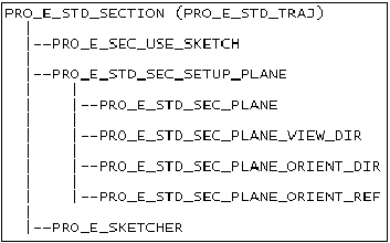
The element tree of any feature that contains a sketch contains a subtree that identifies the sketch object and describes how it is positioned in the model. As this subtree is the same for every sketched feature, it is documented in its own header file, called ProStdSection.h. The diagram below shows the structure of that subtree.
Element Tree for Sketched Features
Image
The subtree of the PRO_E_STD_SEC_SETUP_PLANE element defines the sketch plane, the location of the sketch plane, the orientation plane and the orientation direction, and the viewing direction. You can use Intent Planes as sketch orientation or placement references.
The element PRO_E_SKETCHER is of type POINTER, and its value is the object ProSection, introduced in the documentation in the section on Sections.
The element PRO_E_SEC_USE_SKETCH refers to any valid selected 'Sketch' (sketched datum curve) suitable to the current Sketch Based Feature. When this element is used, the sketch will be stored in the feature as a reference to the sketch feature, and no internal section, sketch plane or orientation will be required. Using this element in the PRO_E_STD_SECTION element tree allows a feature to be created in one step, without creating the feature first as incomplete.
Note
The use of internal sections, and the process by which an internal-section based feature is created, remains unchanged in Pro/ENGINEER Wildfire 2.0.
The following table shows the sketched features that are supported by Creo TOOLKIT, the names of the corresponding header files which show their element trees, and the IDs of the elements in each tree which contain the standard sketch subtree as shown in the above figure Element Tree for Sketched Features
Feature
Header
Element containing Subtree
Extrude
ProExtrude.h
PRO_E_STD_SECTION
Revolve
ProRevolve.h
PRO_E_STD_SECTION
Rib
ProRib.h
PRO_E_STD_SECTION
Hole
ProHole.h
PRO_E_SKETCHER (2D)
PRO_E_STD_SECTION
Fill (Flat datum surface)
ProFlatSrf.h
PRO_E_STD_SECTION
Draft
ProDraft.h
PRO_E_STD_SECTION
Sketched datum curve
ProDtmCrv.h
PRO_E_STD_SECTION
Sketched datum point
ProDtmCrv.h
PRO_E_STD_SECTION
Simple (constant) sweep
ProSweep.h
PRO_E_SWEEP_SPINE
PRO_E_SWEEP_SECTION(2D)
Creating Features Containing Sections
The section Element Trees: Principles of Feature Creation explained that to create a feature from an element tree, you build the tree of elements using ProElementAlloc(), ProElemtreeElementAdd(), and so on, and then call ProFeatureCreate() to create the feature using the tree. If the feature is to contain a sketch, the sequence is a little more complex.
As explained in the documentation in the section section on Element Trees: Sections, a 2D section stored in a model file can be allocated by calling ProSection2dAlloc(). Instead, Creo Parametric must allocate as part of the initial creation of the sketched feature, a section that will be part of a feature. The allocation is done by calling ProFeatureCreate() with an element tree which describes at minimum the feature type and form, in order to create an incomplete feature. In creating the feature, Creo Parametric calculates the location and orientation of the section, and allocates the ProSection object. This section is then retrieved from the value of the PRO_E_SKETCHER element that is found in the element tree extracted from the created feature. Fill the empty section using ProSection related functions.
After adding the section contents and the remaining elements in the tree, add the new information to the feature using ProFeatureRedefine().
To Create Sketched Features Element Trees
1. Build an element tree but do not include the element PRO_E_SKETCHER.
2. Call ProFeatureCreate() with the option PRO_FEAT_CR_INCOMPLETE_FEAT, so that the incomplete element tree is accepted.
3. Extract the value of the element PRO_E_SKETCHER created by Creo Parametric from an element tree extracted using ProFeatureElemtreeExtract() on the incomplete feature.
4. Using that value as the ProSection object, create the necessary section entities and dimensions, and solve the section.
5. Add any other elements not previously added to the tree, such as extrusion depth. The depth elements may also be added before the creation of incomplete feature (before step 2).
6. Call ProFeatureRedefine() with the completed element tree.
Creating Features with 2D Sections
Sketched features using 2D sections do not require references to other geometry in the Creo Parametric model. Some examples of where 2D sections are used are:
•  Base features, sometimes called first features. This type of feature must be the first feature created in the model, and be of type PRO_FEAT_FIRST_FEAT.
•  Sketched hole features.
•  The PRO_E_SWEEP_SECTION section of a simple sweep feature.
To create 2D sketched features, follow the steps outlined in the section To Create Sketched Features Element Trees.
Note
For 2D sketched features, you need not specify section references or use projected 3D entities. Entities in a 2D section are dimensioned to themselves only. A 2D section does not require any elements in the tree to setup the sketch plane or the orientation of the sketch. Thus, the PRO_E_STD_SEC_SETUP_PLANE subtree is not included.
Verifying Section Shapes
Function Introduced:
Certain features may or may not be able to use a section due to the shape of the section. Different sketched feature tools such as extrude and revolve have different requirements for sections. For example, solid protrusions contain only closed and non-intersecting sections. Solid cuts or datum surfaces have open non-intersecting sections. Fill features must have closed sections.
After the section is regenerated, ProSectionShapeGet() obtains the shape of a given section. This information is used to determine if the section is acceptable for feature creation.
The section shapes are as follows:
Constant
Function
Description
PRO_SECSHAPE_EMPTY
ProSectionShapeGet()
An empty section
PRO_SECSHAPE_POINTS
ProSectionShapeGet()
Section contains only sketched datum points
PRO_SECSHAPE_1_OPEN_LOOP
ProSectionShapeGet()
Section contains a single open loop (and possibly points)
PRO_SECSHAPE_1_CLOSED_LOOP
ProSectionShapeGet()
Section contains a single closed loop (and possibly points)
PRO_SECSHAPE_MIXED_LOOPS
ProSectionShapeGet()
Section contains at least one open and one closed loop (and possibly points)
PRO_SECSHAPE_MULTI_OPEN_LOOPS
ProSectionShapeGet()
Section contains multiple open loops (and possibly points)
PRO_SECSHAPE_MULTI_CLOSED_LOOPS
ProSectionShapeGet()
Section contains multiple closed loops (and possibly points)
PRO_SECSHAPE_INTERSECTING
ProSectionShapeGet()
Section contains loops that intersect each other (and possibly points)
Note
Use geometry entities and not construction entities to define section shapes that are then used to create solid or surface geometry. To convert the construction entities to geometry entities, use the function ProSectionEntityConstructionSet() with the input argument construction set to PRO_B_FALSE.
Creating Features with 3D Sections
A 3D section needs to define its location with respect to the existing geometrical features. The subtree contained in the element PRO_STD_SEC_SETUP_PLANE defines the location of the sketch planeEdge entities; any other 2D entities in the sketch must be dimensioned to those entities, so that their 3D location is fully defined.
3D Section Location in the Owning Model
Function Introduced:
For a 2D section in a feature, Creo Parametric decides where the section will be positioned in 3D.
If the section is 3D, the feature tree elements below PRO_E_STD_SEC_SETUP_PLANE specify the sketch plane, the direction from which it is being viewed, an orientation reference, and a direction which that reference represents (TOP, BOTTOM, LEFT or RIGHT). When you call ProFeatureCreate(), this information is used to calculate the 3D plane in which the section lies, and its orientation in that plane.
The position of the section origin in the plane is not implied by the element tree, and cannot be specified by the Creo TOOLKIT application: position is chosen arbitrarily by Creo Parametric. This is because the interactive user of Creo Parametric never deals in absolute coordinates, and doesn’t need to specify, or even know, the location of the origin of the section. In Creo TOOLKIT describe all section entities in terms of their coordinate values, so you need to find out where Creo Parametric has put the origin of the section. This is the role of the function ProSectionLocationGet().
ProSectionLocationGet() provides the transformation matrix that goes from 2D coordinates within the section to 3D coordinates of the owning part or assembly. This is equivalent to describing the position and orientation of the 2D section coordinate system with respect to the base coordinate system of the 3D model.
So ProSectionLocationGet() can be called in order to calculate where to position new section entities so that they are in the correct 3D position in the part or assembly.
Reference Entities and Use Edge
Functions introduced:
The previous section explained how to set the correct 3D position of new section entities. You also need to make the entities parametric, that is, to ensure that Creo Parametric knows how to calculate their new positions during regeneration.
When sketching a section using Creo Parametric, entities are positioned parametrically by dimensioning them or aligning them to items in the 3D model. Creo TOOLKIT does not allow you to explicitly align section entities, but you can add dimensions which relate section entities to 3D entities in the owning model. You can do this using references. A reference entity represents a position in the section of an item in a 3D model that is used as a dimension reference. The reference entity itself does not give rise to 3D geometry in the owning feature. Reference entities are visible in interactive sketcher operations; they are shown as dashed and are used during autodimensioning and alignment operations.
In Creo TOOLKIT reference entities are created using ProSectionEntityFromProjection(). This function takes as input a ProSelection describing the 3D model entity being projected, and outputs the integer ID of the resulting known section entity. This ID is used to specify the attachment of a section dimension, as described in the documentation in the section section Element Trees: Sections. Reference entities are included in the output of ProSectionEntityIdsGet(), but can be distinguished from regular section entities by calling the function ProSectionEntityIsProjection().
To align a section entity with a 3D model entity, project the 3D entity to create a reference entity, and then either add a dimension between this reference entity and the one to be aligned or use ProSectionAutodim() to do this.
To create a regular section entity whose geometry is itself an exact projection of a 3D model entity, create it and align it in a single step using the function ProSectionEntityUseEdge(). This function has the same arguments as ProSectionEntityFromProjection(), and it creates a reference entity in the same way, but it requires an additional step of copying the reference entity to a regular entity with the same geometry. It outputs the ID of the regular entity it creates. The ID of the reference entity is always 1 less than the ID of the regular entity.
ProSectionEntityUseEdge() is equivalent to the Creo Parametric sketcher command Use Edge. The functions ProSectionEntityUseEdgeLoop() and ProSectionEntityUseEdgeChain() allow you to execute a Use Edge operation on multiple edges simultaneously.
Note
If you create the known and projected entities first, you need not call ProSectionLocationGet() as described above; instead you can look at the geometry of the known and projected entities, and then position the new entities relative to the projected entities.
The function ProSectionEntityReferenceGet() provides 3D geometry that is a reference for a projected entity in a given section.
Creating Geometry by Offsetting
The functions described in this section enable you to create offset entities from edges and 3D curve segments from normal, chain and loop selection.
Functions Introduced:
The function ProSectionEntityUseOffset() creates a sketched entity that is offset at a specified distance from a single edge. This function takes as input a ProSelection object describing the 3D model entity.
The function ProSectionEntityUseOffsetChain() creates sketched entities that are offset from a chain of edges or entities and the function ProSectionEntityUseOffsetLoop() creates sketched entities offset from a loop of edges or entities.
The behavior of the functions in this section is similar to the offset operation achieved using Sketch  Offset in Creo Parametric.
Reusing Existing Sketches
Functions introduced:
Creo Parametric allows you to copy sections from previously created features into new sketched features.
The function ProFeatureSketchAdd() copies the selected section from one feature to another feature.
The function ProFeatureSketchedWithOptionsCreate() creates a feature from the element tree, and also copies the sketched sections to the new feature. This reduces the sketched feature creation effort to a single Creo TOOLKIT function call. The element tree must contain all of the required elements except the PRO_E_STD_SECTION subtree.
Example 1: Creating an Extruded Protrusion Base Feature
The sample code in UgSktExtrusionCreate.c located at <creo_toolkit_loadpoint>/protk_appls/pt_userguide/ptu_featcreat shows the creation of an extruded protrusion as a base feature.
Example 2: Creating a Sketched Datum Curve
The sample code in UgSketchedCurveCreate.c located at <creo_toolkit_loadpoint>/protk_appls/pt_userguide/ptu_featcreat shows the creation of a sketched datum curve using the conventional approach.