Element Trees: Extrude and Revolve
This section describes how to use the include files ProExtrude.h, and ProRevolve.h so that you can create extruded and revolved features programmatically. As Extrude and Revolve features are sketched features; we recommend you to read the sections Element Trees: Principles of Feature Creation and Element Trees: Sketched Features before referring to this section.
The Element Tree for Extruded Features
The element tree for extrude features is documented in the header file ProExtrude.h. The functions ProFeatureTypeGet() and ProFeatureSubtypeGet() return an Extrude feature. The types of Extrude features are:
•  Protrusion
•  Cut
•  Surface
•  Surface Trim
•  Thin Protrusion
•  Thin Cut
•  Sheetmetal Cut
•  Sheetmetal Unattached Wall
g
Refer to the section Production Applications: Sheetmetal for element details on sheetmetal features.
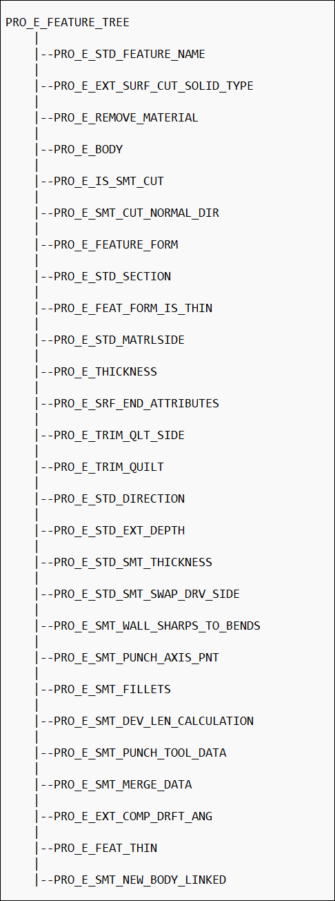
The extrude element tree contains toggles to switch between different feature types. An extruded feature tree also contains subtrees supporting the section and depth parameters for the feature.
You can use Intent Datums such as Intent Point, Intent Axis, and Intent Plane for depth reference in extrude features.
The following figure shows the element tree for extruded features.
The Element Tree for Extruded Feature
Image
The elements are assigned values depending on the type of extrusion you want to create.
The following table lists the common elements for all types of extrusions and their permissible values:
Element ID
Value
PRO_E_FEATURE_TYPE
Feature type, not required for creation: PRO_FEAT_PROTRUSION
PRO_FEAT_CUT
PRO_FEAT_DATUM_SURFN
PRO_E_FEATURE_FORM
Mandatory = PRO_EXTRUDE
PRO_E_EXT_SURF_CUT_SOLID_TYPE
Mandatory
Of type ProExtFeatType
= PRO_EXT_FEAT_TYPE_SOLID
for Solid feature type
= PRO_EXT_FEAT_TYPE_SURFACE
for Surface feature type
PRO_E_REMOVE_MATERIAL
Material Removal
Of type ProExtRemMaterial
= PRO_EXT_MATERIAL_ADD
for a Protruded feature
= PRO_EXT_MATERIAL_REMOVE
for a Cut feature
PRO_E_STD_SECTION
Standard section elements
PRO_E_BODY
Compound Element. Specifies the body options.
PRO_E_STD_DIRECTION*
Direction of creation.
Of type ProExtDirection
= PRO_EXT_CR_IN_SIDE_ONE
for depth in side one
= PRO_EXT_CR_IN_SIDE_TWO
for depth in side two
PRO_E_STD_MATRLSIDE*
Direction of material affected with respect to the sketch. Required for all cuts, all thin features, and for solid protrusions with open sections.
PRO_E_STD_EXT_DEPTH
Compound Element. Specifies the depth type and value for the extrude feature.
PRO_E_EXT_DEPTH_TO
Compound Element. Specifies the depth type and value for Side 1, that is, extrusion in the first direction from the sketch plane.
PRO_E_EXT_DEPTH_TO_TYPE
Mandatory element. Specifies the type of depth for Side 1. The depth type is specified using the enumerated data type ProExtDepthToType. The valid values are:
•  PRO_EXT_DEPTH_TO_BLIND—Extrudes a section from the sketching plane to the specified depth value.
•  PRO_EXT_DEPTH_TO_NEXT—Extrudes a section from the sketching plane to the first surface that it reaches.
•  PRO_EXT_DEPTH_TO_ALL—Extrudes a section from the sketching plane to the last surface it reaches.
•  PRO_EXT_DEPTH_TO_UNTIL—Extrudes a section to intersect with a selected surface.
•  PRO_EXT_DEPTH_TO_REF—Extrudes a section to a selected point, curve, plane, or surface.
•  PRO_EXT_DEPTH_SYMMETRIC—Extrudes a section on each side of the sketching plane by half of the specified depth value in each direction.
PRO_E_EXT_DEPTH_TO_REF
Specifies the reference element for Side 1, when the depth type is PRO_EXT_DEPTH_TO_REF or PRO_EXT_DEPTH_TO_UNTIL. The valid reference types are:
•  PRO_SURFACE
•  PRO_AXIS
•  PRO_EDGE
•  PRO_CURVE
•  PRO_POINT
•  PRO_EDGE_START
•  PRO_EDGE_END
•  PRO_CRV_START
•  PRO_CRV_END
•  PRO_BODY
PRO_E_EXT_DEPTH_TO_REF_TRF
Specifies the options available for the depth type PRO_EXT_DEPTH_TO_REF for Side 1. The depth type is specified using the enumerated data type ProExtDepthRefOpt. The valid values are:
•  PRO_EXT_DEPTH_REF_NONE—Extrudes a section to a selected point, curve, plane, or surface.
•  PRO_EXT_DEPTH_REF_OFFS—Extrudes a section to an offset of the selected point, curve, plane, or surface.
•  PRO_EXT_DEPTH_REF_TRNSLT—Extrudes a section to a translation of the selected point, curve, plane, or surface.
PRO_E_EXT_DEPTH_TO_REF_TRF_VAL
Specifies the offset or translation value for Side 1, when the depth type is PRO_EXT_DEPTH_TO_REF, and the option type is PRO_EXT_DEPTH_REF_OFFS or PRO_EXT_DEPTH_REF_TRNSLT.
PRO_E_EXT_DEPTH_TO_VALUE
Specifies the value of depth for Side 1, when the depth type is PRO_EXT_DEPTH_TO_BLIND or PRO_EXT_DEPTH_SYMMETRIC.
PRO_E_EXT_DEPTH_FROM
Compound Element. Specifies the depth type and value for Side 2, that is, extrusion in the second direction from the sketch plane.
PRO_E_EXT_DEPTH_FROM_TYPE
Mandatory element. Specifies the type of depth for Side 2. The depth type is specified using the enumerated data type ProExtDepthFromType. The valid values are:
•  PRO_EXT_DEPTH_FROM_BLIND—Extrudes a section from the sketching plane to the specified depth value.
•  PRO_EXT_DEPTH_FROM_NEXT—Extrudes a section from the sketching plane to the first surface that it reaches.
•  PRO_EXT_DEPTH_FROM_ALL—Extrudes a section from the sketching plane to the last surface it reaches.
•  PRO_EXT_DEPTH_FROM_UNTIL—Extrudes a section to intersect with a selected surface.
•  PRO_EXT_DEPTH_FROM_REF—Extrudes a section to a selected point, curve, plane, or surface.
•  PRO_EXT_DEPTH_FROM_NONE—Extrudes a section only on Side 1 from the sketch plane, no extrusion on Side 2.
PRO_E_EXT_DEPTH_FROM_REF
Specifies the reference element for Side 2, when the depth type is PRO_EXT_DEPTH_FROM_REF or PRO_EXT_DEPTH_FROM_UNTIL. The valid reference types are:
•  PRO_SURFACE
•  PRO_AXIS
•  PRO_EDGE
•  PRO_CURVE
•  PRO_POINT
•  PRO_EDGE_START
•  PRO_EDGE_END
•  PRO_CRV_START
•  PRO_CRV_END
•  PRO_BODY
PRO_E_EXT_DEPTH_FROM_REF_TRF
Specifies the options available for the depth type PRO_EXT_DEPTH_FROM_REF for Side 2. The depth type is specified using the enumerated data type ProExtDepthRefOpt. The valid values are:
•  PRO_EXT_DEPTH_REF_NONE—Extrudes a section to a selected point, curve, plane, or surface.
•  PRO_EXT_DEPTH_REF_OFFS—Extrudes a section to an offset of the selected point, curve, plane, or surface.
•  PRO_EXT_DEPTH_REF_TRNSLT—Extrudes a section to a translation of the selected point, curve, plane, or surface.
PRO_E_EXT_DEPTH_FROM_REF_TRF_VAL
Specifies the offset or translation value for Side 2, when the depth type is PRO_EXT_DEPTH_FROM_REF, and the option type is PRO_EXT_DEPTH_REF_OFFS or PRO_EXT_DEPTH_REF_TRNSLT.
PRO_E_EXT_DEPTH_FROM_VALUE
Specifies the value of depth for Side 2, when the depth type is PRO_EXT_DEPTH_FROM_BLIND.
PRO_E_STD_FEATURE_NAME
Default given by application depending
on the feature type. Can be modified by the user.
PRO_E_EXT_COMP_DRFT_ANG
Draft Compound Element that allows you to add a draft on the extrude feature.
PRO_E_EXT_DRFT_ANG
Draft of type ProExtDrftAng.
•  PRO_EXT_DRFT_ANG_NO_DRAFT—To create extruded features without a draft.
•  PRO_EXT_DRFT_ANG_DRAFT—To create extruded features with a draft.
PRO_E_EXT_DRFT_ANG_VAL
The draft angle. The draft angle can have value between [-89.9, 89.9].
PRO_E_FEAT_THIN
Compound element. It specifies how to close a thin feature when one or more surfaces can be used to cap, that is, close the feature and attach it to the solid geometry. Here the sketch is an open sketch.
PRO_E_FEAT_THIN_STRT
Compound element. It specifies the options for the first end point of the thin feature.
PRO_E_FEAT_THIN_STRT_OPT
Specifies how to cap the first end point of the thin feature using the enumerated data type ProFeatThinOpt. The valid values are:
•  PRO_FEAT_THIN_IGNORE—Caps the feature as a free end. When you specify this value, the feature is created with a free end even if a reference edge or surface is available to cap the feature.
•  PRO_FEAT_THIN_DEFAULT—Caps the feature to the specified edge or surface.
PRO_E_FEAT_THIN_STRT_REF
Specifies the edge or surface that must be used to cap and attach the first end point of the feature to the solid geometry.
PRO_E_FEAT_THIN_END
Compound element. It specifies the options for the second end point of the feature.
PRO_E_FEAT_THIN_END_OPT
Specifies how to cap the second end point of the thin feature using the enumerated data type ProFeatThinOpt. The valid values are:
•  PRO_FEAT_THIN_IGNORE—Caps the feature as a free end. When you specify this value, the feature is created with a free end even if a reference edge or surface is available to cap the feature.
•  PRO_FEAT_THIN_DEFAULT—Caps the feature to the specified edge or surface.
PRO_E_FEAT_THIN_END_REF
Specifies the edge or surface that must be used to cap and attach the second end point to the solid geometry.
PRO_E_SMT_NEW_BODY_LINKED
Specifies if the sheetmetal body is linked to a part.
Elements identified with ‘*’ depend on the definition of the standard section. These elements are not assigned values until the standard section has been completely allocated (which typically happens during redefine of the feature). Values assigned to these elements while the section is not complete are ignored.
The following table lists the elements needed to create extruded features, in addition to those already discussed:
Feature Type
Element ID
Comment
Solid
PRO_E_EXT_COMP_DRFT_ANG
Compound element to specify draft options.
PRO_E_BODY
Compound element
PRO_E_BODY_USE
Mandatory. Specifies the body to add geometry to.
The valid values are:
•  PRO_BODY_USE_NEW—The geometry in the feature is stored in the new body.
•  PRO_BODY_USE_SELECTED—The geometry in the feature is stored in the single selected body.
PRO_E_BODY_SELECTED
Specifies the reference to the selected body.
Mandatory if PRO_E_BODY_USE is set to PRO_BODY_USE_SELECTED
Note
Only single reference is allowed.
Thin
PRO_E_THICKNESS
Mandatory >= 0.0
Of type PRO_VALUE_TYPE_DOUBLE
PRO_E_BODY
Compound element
PRO_E_BODY_USE
Mandatory. The valid values for PRO_BODY_USE_NEW and PRO_BODY_USE_SELECTED are same as Solid.
PRO_E_BODY_SELECTED
Same as Solid.
PRO_E_FEAT_FORM_IS_THIN
Of Type ProExtFeatForm
= PRO_EXT_FEAT_FORM_NO_THIN for a feature not having Thin
= PRO_EXT_FEAT_FORM_THIN for a Thin feature
PRO_E_STD_MATRLSIDE
Mandatory
Of type ProExtMatlSide
PRO_E_FEAT_THIN
Compound element to specify options to cap and attach thin features to solid geometry.
Solid Cut
PRO_E_BODY
Compound element
PRO_E_BODY_USE
Mandatory. Specifies the body features that cuts the geometry.
The valid values are:
•  PRO_BODY_USE_ALL—The geometry in the feature is cut by all the existing bodies.
•  PRO_BODY_USE_SELECTED—The geometry in the feature is stored in the selected bodies.
PRO_E_BODY_SELECTED
Specifies the reference to the selected bodies.
Mandatory if PRO_E_BODY_USE is set to PRO_BODY_USE_SELECTED
Note
Multiple references are allowed.
PRO_E_STD_MATRLSIDE
Mandatory
Of type ProExtMatlSide
PRO_E_EXT_COMP_DRFT_ANG
Draft compound element for features that do not have feature form as Thin.
PRO_E_FEAT_FORM_IS_THIN
Of Type ProExtFeatForm
= PRO_EXT_FEAT_FORM_NO_THIN for a feature not having Thin
= PRO_EXT_FEAT_FORM_THIN for a Thin feature
Thin Cut
PRO_E_BODY
Compound element
PRO_E_BODY_USE
Same as Solid Cut
PRO_E_BODY_SELECTED
Same as Solid Cut
PRO_E_STD_MATRLSIDE
Mandatory
Of type ProExtMatlSide
PRO_E_THICKNESS
Mandatory >= 0.0
Of type PRO_VALUE_TYPE_DOUBLE
PRO_E_FEAT_FORM_IS_THIN
Of Type ProExtFeatForm
= PRO_EXT_FEAT_FORM_NO_THIN for a feature not having Thin
= PRO_EXT_FEAT_FORM_THIN for a Thin feature
Surface
PRO_E_SRF_END_ATTRIBUTES
Mandatory
Of type ProExtSurfEndAttr
It must be assigned at the same time or after the section is fully completed.
PRO_E_EXT_COMP_DRFT_ANG
Draft compound element for features that do not have feature form as Thin.
PRO_E_FEAT_FORM_IS_THIN
Of Type ProExtFeatForm
= PRO_EXT_FEAT_FORM_NO_THIN for a feature not having Thin
= PRO_EXT_FEAT_FORM_THIN for a Thin feature
Surface Trim
PRO_E_STD_MATRLSIDE
Mandatory
Of type ProExtMatlSide
PRO_E_TRIM_QUILT
Mandatory
Of type Quilt
PRO_E_TRIM_QLT_SIDE
Mandatory
Of typeProExtTrimQltSide
PRO_E_FEAT_FORM_IS_THIN
Of Type ProExtFeatForm
= PRO_EXT_FEAT_FORM_NO
_THIN
for a feature not having Thin
= PRO_EXT_FEAT_FORM
_THIN
for a Thin feature
PRO_E_EXT_COMP_DRFT_ANG
Draft compound element for features that do not have feature form as Thin.
Thin Surface Trim
PRO_E_STD_MATRLSIDE
Mandatory
Of type ProExtMatlSide
PRO_E_THICKNESS
Mandatory >= 0.0
Of type PRO_VALUE_TYPE_DOUBLE
PRO_E_TRIM_QUILT
Mandatory
Of type Quilt
PRO_E_TRIM_QLT_SIDE
Mandatory
Of type ProExtTrimQltSide
if PRO_E_STD_MATRLSIDE is “both”. Must be assigned at the same time as PRO_E_STD_MATRLSIDE.
PRO_E_FEAT_FORM_IS_THIN
Of Type ProExtFeatForm
= PRO_EXT_FEAT_FORM_NO
_THIN
for a feature not having Thin
= PRO_EXT_FEAT_FORM_THIN for a Thin feature
Examples: Creating Extruded Features
The following examples demonstrate creation of extrude features of various forms. These examples are adapted from an example template file UgSktExtrusionTemplate.c available on the Creo Parametric load point under protoolkit/protk_appls/pt_userguide/ptu_featcreat.
Conventional Approach
Example 1: Creating an Extruded Feature
The sample code in the file UserSktExtrusionProtrusion.c located at <creo_toolkit_loadpoint>/protk_appls/pt_userguide/ptu_featcreat shows how to create an Extruded Protrusion by the conventional approach for sketched features. The example creates an incomplete feature using ProFeatureCreate(), extracts the section from the element tree of the incomplete feature, builds the section on the section handle obtained, and, completes the feature using ProFeatureRedefine().
The user is prompted to select the sketching and the orientation planes and then the reference edges for the sketch. The user is also required to enter the X and Y offsets to be applied to the sketch from the projected edges.
Example 2: To Create an Extruded Cut with Two-sided Thru-all Depth
The sample code in the file UgSktExtrusionCut.c located at <creo_toolkit_loadpoint>/protk_appls/pt_userguide/ptu_featcreat shows how to create an extruded cut with two-sided thru-all depth.
Example 3: To Create an Extruded Thin Cut
The sample code in the file UgSktExtrusionCut.c located at <creo_toolkit_loadpoint>/protk_appls/pt_userguide/ptu_featcreat shows how to create an extruded thin cut. Its depth is two-sided, up to a selected reference.
Example 4: To Create an Extruded Datum Surface Feature
The sample code in the file UgSktExtrusionSurfaceCapped.c located at <creo_toolkit_loadpoint>/protk_appls/pt_userguide/ptu_featcreat shows how to create an extruded datum surface feature. Its depth is one-side blind.
Example 5: To Create a Surface Trim Extruded Feature
The sample code in the file UgSktExtrusionSurfaceTrim.c located at <creo_toolkit_loadpoint>/protk_appls/pt_userguide/ptu_featcreat shows how to create an extruded surface trim. Its depth is one-side blind.
Direct Creation Approach
The sample code in the file UgSktExtrusionCreate.c located at <creo_toolkit_loadpoint>/protk_appls/pt_userguide/ptu_featcreat shows how to create an extruded protrusion by the direct approach for sketched features introduced in Pro/ENGINEER Wildfire. The user is prompted to select a sketched datum curve feature that is used as a section for the created protrusion.
The Element Tree for Revolved Features
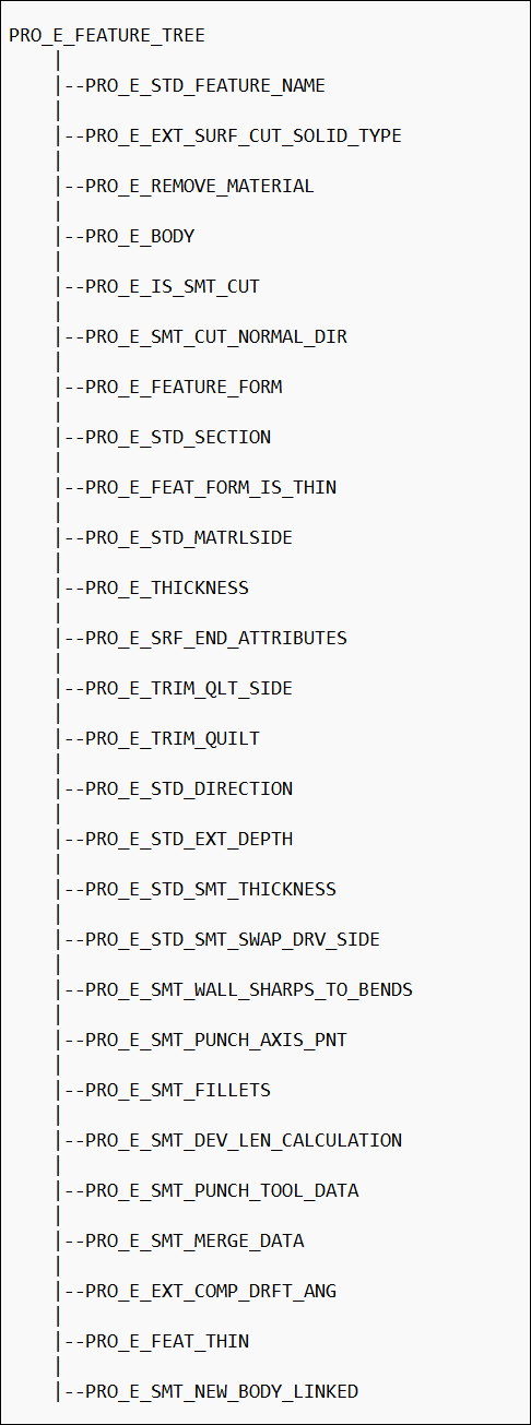
The element tree for revolved features is documented in the header file ProRevolve.h, and has a fairly simple structure. It shows that, apart from the usual elements for the tree root and feature name, a revolved feature tree contains the elements to make the feature a solid protrusion, a thin protrusion, a solid cut, a thin cut, a surface, a surface trimmed feature, or a thin surface trimmed feature.
You can use Intent Datums such as Intent Axis, Intent Plane, and Intent Point for placement references.
The following figure shows the element tree for revolved features.
Element Tree for Revolved Feature
Image
The elements are assigned values depending on the type of revolved feature you want to create.
The following table lists the common elements for all types of revolved features and their permissible values:
Element ID
Value
PRO_E_FEATURE_TYPE
Feature type:
PRO_FEAT_PROTRUSION
PRO_FEAT_CUT
PRO_FEAT_DATUM_SURF
Not required for creation.
PRO_E_FEATURE_FORM
Mandatory= PRO_REVOLVE
PRO_E_EXT_SURF_CUT_SOLID_TYPE
Mandatory
Of type ProRevFeatType
= PRO_REV_FEAT_TYPE_SOLID
for Solid feature type
= PRO_REV_FEAT_TYPE_SURFACE
for Surface feature type
PRO_E_FEAT_FORM_IS_THIN
Feature Form
Of Type ProRevFeatForm
= PRO_REV_FEAT_FORM_NO
_THIN
for a Solid feature
= PRO_REV_FEAT_FORM_THIN
for a Thin feature
PRO_E_REMOVE_MATERIAL
Material Removal
Of type ProRevRemMaterial
= PRO_REV_MATERIAL_ADD
for a Protruded feature
= PRO_REV_MATERIAL_REMOVE
for a Cut feature
PRO_E_STD_SECTION
Standard section elements.
PRO_E_BODY
Compound Element
PRO_E_STD_DIRECTION*
Direction of creation.
Of type ProRevDirection
= PRO_REV_CR_IN_SIDE_ONE
for angle in side one
= PRO_REV_CR_IN_SIDE_TWO
for angle in side two
PRO_E_STD_MATRLSIDE*
Direction of material affected with respect to the sketch. It is required for all cuts, all thin features, and for solid protrusions with open sections.
PRO_E_REVOLVE_AXIS_OPT
Optional, of the type ProRevAxisOptAttr. Identifies if the axis to revolve about is a part of the sketch or an external datum axis.
PRO_E_REVOLVE_AXIS
Optional. Reference to external datum axis, if PRO_E_REVOLVE_AXIS = PRO_REV_AXIS_EXT_REF.
PRO_E_REV_ANGLE
Compound Element
PRO_E_REV_ANGLE_TO
Compound Element
PRO_E_REV_ANGLE_TO_TYPE
Mandatory
Of type ProRevAngleToType
PRO_E_REV_ANGLE_TO_VAL
Depends on PRO_E_REV_ANGLE_TO_TYPE
Of type PRO_VALUE_TYPE_DOUBLE (in degrees)
PRO_E_REV_ANGLE_TO_REF
Depends on PRO_E_REV_ANGLE_TO_TYPE
Of type listed in the Angle Type table that follows.
PRO_E_REV_ANGLE_FROM
Compound Element
PRO_E_REV_ANGLE_FROM_TYPE
Mandatory
Of type ProRevAngleFromType
PRO_E_REV_ANGLE_FROM_VAL
Depends on PRO_E_REV_ANGLE_FROM_TYPE
Of type PRO_VALUE_TYPE_DOUBLE (in degrees)
PRO_E_REV_ANGLE_FROM_REF
Depends on PRO_E_REV_ANGLE_FROM_TYPE
Of type listed in the Angle Type table that follows.
PRO_E_STD_FEATURE_NAME
Default given by application depending
on the feature type. Can be modified by the user.
PRO_E_FEAT_THIN
Compound element. It specifies how to close a thin feature when one or more surfaces can be used to cap, that is, close the feature and attach it to solid geometry. Here the sketch is an open sketch.
PRO_E_FEAT_THIN_STRT
Compound element. It specifies the options for the first end point of the thin feature.
PRO_E_FEAT_THIN_STRT_OPT
Specifies how to cap the first end point of the thin feature using the enumerated data type ProFeatThinOpt. The valid values are:
•  PRO_FEAT_THIN_IGNORE—Caps the feature as a free end. When you specify this value, the feature is created with a free end even if a reference edge or surface is available to cap the feature.
•  PRO_FEAT_THIN_DEFAULT—Caps the feature to the specified edge or surface.
PRO_E_FEAT_THIN_STRT_REF
Specifies the edge or surface that must be used to cap and attach the first end point to the solid geometry.
PRO_E_FEAT_THIN_END
Compound element. It specifies the options for the second end point of the thin feature.
PRO_E_FEAT_THIN_END_OPT
Specifies how to cap the second end point of the thin feature using the enumerated data type ProFeatThinOpt. The valid values are:
•  PRO_FEAT_THIN_IGNORE—Caps the feature as a free end. When you specify this value, the feature is created with a free end even if a reference edge or surface is available to cap the feature.
•  PRO_FEAT_THIN_DEFAULT—Caps the feature to the specified edge or surface.
PRO_E_FEAT_THIN_END_REF
Specifies the edge or surface that must be used to cap and attach the second end point to the solid geometry.
PRO_E_SMT_NEW_BODY_LINKED
Specifies if the sheetmetal body is linked to a part.
Elements identified with ‘*’ depend on the definition of the standard section. These elements may not be assigned values until the standard section has been completely allocated (which typically happens during redefine of the feature). Values assigned to these elements while the section is not complete are ignored.
The following table lists the angle types for revolved features along with possible valid references:
Angle Type
Valid Reference Types
PRO_REV_ANGLE_TO_REF
PRO_POINT, PRO_EDGE_START, PRO_EDGE_END, PRO_CRV_START, PRO_CRV_END, PRO_SURFACE (Plane).
PRO_REV_ANGLE_FROM_REF
PRO_POINT, PRO_EDGE_START, PRO_EDGE_END, PRO_CRV_START, PRO_CRV_END, PRO_SURFACE (Plane).
The following table lists the elements needed to create revolved features, in addition to those already discussed:
Feature Type
Element ID
Comment
Solid
PRO_E_BODY
Compound element
PRO_E_BODY_USE
Mandatory. Specifies the body to add geometry to.
The valid values are:
•  PRO_BODY_USE_NEW—The geometry in the feature is stored in the new body.
•  PRO_BODY_USE_SELECTED—The geometry in the feature is stored in the single selected body.
PRO_E_BODY_SELECTED
Specifies the reference to the selected body.
Mandatory if PRO_E_BODY_USE is set to PRO_BODY_USE_SELECTED
Note
Only single reference is allowed.
Thin
PRO_E_STD_MATRLSIDE
Mandatory
Of type ProRevMatlSide
PRO_E_BODY
Compound element
PRO_E_BODY_USE
Same as Solid
PRO_E_BODY_SELECTED
Same as Solid
PRO_E_THICKNESS
Mandatory >= 0.0
Of type PRO_VALUE_TYPE_DOUBLE
PRO_E_FEAT_FORM_IS_THIN
Of Type ProRevFeatForm
= PRO_REV_FEAT_FORM_NO
_THIN
for feature not having Thin
= PRO_REV_FEAT_FORM_THIN for a Thin feature
PRO_E_FEAT_THIN
Compound element to specify options to cap and attach thin features to solid geometry.
Solid Cut
PRO_E_BODY
Compound element
PRO_E_BODY_USE
Mandatory. Specifies the body features that cuts the geometry.
The valid values are:
•  PRO_BODY_USE_ALL—The geometry in the feature is cut by all the existing bodies.
•  PRO_BODY_USE_SELECTED—The geometry in the feature is stored in the selected bodies.
PRO_E_BODY_SELECTED
Specifies the reference to the selected bodies.
Mandatory if PRO_E_BODY_USE is set to PRO_BODY_USE_SELECTED
Note
Multiple references are allowed.
PRO_E_STD_MATRLSIDE
Mandatory
Of type ProRevMatlSide
PRO_E_FEAT_FORM_IS_THIN
Of Type ProRevFeatForm
= PRO_REV_FEAT_FORM_NO
_THIN
for feature not having Thin
= PRO_REV_FEAT_FORM_THIN for a Thin feature
Thin Cut
PRO_E_BODY
Compound element
PRO_E_BODY_USE
Same as Solid Cut
PRO_E_BODY_SELECTED
Same as Solid Cut
PRO_E_STD_MATRLSIDE
Mandatory
Of type ProRevMatlSide
PRO_E_THICKNESS
Mandatory >= 0.0
Of type PRO_VALUE_TYPE_DOUBLE
PRO_E_FEAT_FORM_IS_THIN
Of Type ProRevFeatForm
= PRO_REV_FEAT_FORM_NO_THIN for feature not having Thin
= PRO_REV_FEAT_FORM_THIN for a Thin feature
Surface
PRO_E_SRF_END_ATTRIBUTES
Mandatory
Of type ProRevSurfEndAttr
Must be assigned at the same time or after the section is fully completed.
PRO_E_FEAT_FORM_IS_THIN
Of Type ProRevFeatForm
= PRO_REV_FEAT_FORM_NO
_THIN
for feature not having Thin
= PRO_REV_FEAT_FORM_THIN for a Thin feature
Surface Trim
PRO_E_STD_MATRLSIDE
Mandatory
Of type ProRevMatlSide
PRO_E_TRIM_QUILT
Mandatory
Of type Quilt
PRO_E_TRIM_QLT_SIDE
Mandatory
Of type ProRevTrimQltSide if PRO_E_STD_MATRLSIDE is “both”. Must be assigned at the same time as PRO_E_STD_MATRLSIDE.
PRO_E_FEAT_FORM_IS_THIN
Of Type ProRevFeatForm
= PRO_REV_FEAT_FORM_NO
_THIN
for feature not having Thin
= PRO_REV_FEAT_FORM_THIN for a Thin feature
Thin Surface Trim
PRO_E_STD_MATRLSIDE
Mandatory
Of type ProRevMatlSide
PRO_E_THICKNESS
Mandatory >= 0.0
Of type PRO_VALUE_TYPE_DOUBLE
PRO_E_TRIM_QUILT
Mandatory
Of type Quilt
PRO_E_TRIM_QLT_SIDE
Mandatory
Of type ProRevTrimQltSide
PRO_E_FEAT_FORM_IS_THIN
Of Type ProRevFeatForm
= PRO_REV_FEAT_FORM_NO
_THIN
for feature not having Thin
= PRO_REV_FEAT_FORM_THIN for a Thin feature
Examples: Creating Revolved Features
The following examples demonstrate creation of revolved features of various forms. These examples are adapted from an example template file UgSktRevolveTemplate.c available on the Creo Parametric loadpoint under <creo_toolkit_loadpoint>/protk_appls/pt_userguide/ptu_featcreat.
Example 6: To Create a Revolved Protrusion
The sample code in the file UgSktRevolveProtrusion.c located at <creo_toolkit_loadpoint>/protk_appls/pt_userguide/ptu_featcreat shows how to create a revolved protrusion feature with symmetric depth.
Example 7: To Create a Revolved Thin Cut
The sample code in the file UserSktRevolveThinCut.c located at <creo_toolkit_loadpoint>/protk_appls/pt_userguide/ptu_featcreat shows how to create a revolved thin cut, with independent angular dimensions for both sides.
Example 8: To Create a Revolved Surface
The sample code in the file UgSktRevolveSurface.c located at <creo_toolkit_loadpoint>/protk_appls/pt_userguide/ptu_featcreat shows how to create a revolved surface. It includes all possible element assignments. By following the instructions for the feature you want to create, it is possible to remove element settings not appropriate for your use.
The Element Tree for First Features
First features (extrude and revolve solids created as the first feature in a part) require a subset of the standard element tree and some special handling for the section pointer.
The following table lists the elements applicable to first feature creation (extrude or revolve):
Element ID
Value
PRO_E_FEATURE_TYPE
Feature type: PRO_FEAT_FIRST
PRO_E_FEATURE_FORM
PRO_EXTRUDE / PRO_REVOLVE
PRO_E_FEAT_FORM_IS_THIN
Feature Form
Of Type ProRevFeatForm
= PRO_REV_FEAT_FORM_NO_THIN for a Solid feature = PRO_REV_FEAT_FORM_THIN for a Thin feature
PRO_E_BODY_USE
Mandatory. Specifies the body to add geometry to.
The valid values are:
•  PRO_BODY_USE_NEW—The geometry in the feature is stored in the new body.
•  PRO_BODY_USE_SELECTED—The geometry in the feature is stored in the single selected body.
PRO_E_BODY_SELECT
Specifies the reference to the selected body.
Mandatory if PRO_E_BODY_USE is set to PRO_BODY_USE_SELECTED
Note
Only single reference is allowed.
PRO_E_SKETCHER
Sketcher pointer. Used because the standard section requires selected references not available in an empty model.
PRO_E_STD_MATRLSIDE*
Mandatory if thin
Of type ProExtMatlSide (Extrude)
Of type ProRevMatlSide (Revolve)
PRO_E_THICKNESS
Mandatory >= 0.0 if thin
Of type PRO_VALUE_TYPE_DOUBLE
PRO_E_EXT_DEPTH_FROM
Compound Element (Extrude only)
PRO_E_EXT_DEPTH_FROM_VAL
Depth dimension (of type PRO_VALUE_TYPE_DOUBLE) (Extrude only)
PRO_E_REV_ANGLE_FROM
Compound Element (Revolve only)
PRO_E_REV_ANGLE_FROM_VAL
Angular dimension (of type PRO_VALUE_TYPE_DOUBLE)
(Revolve only)
PRO_E_STD_FEATURE_NAME
Default given by application depending on the feature type. Can be modified by the user.
Elements identified with ‘*’ depend on the definition of the standard section. These elements may not be assigned values until the standard section has been completely allocated (which typically happens during redefine of the feature). Values assigned to these elements while the section is not complete are ignored.
Example 9: Creating the First Extruded Protrusion Feature by Conventional Approach
The sample code in the file UgSktFirstFeatureCreate.c located at <creo_toolkit_loadpoint>/protk_appls/pt_userguide/ptu_featcreat shows how to create the first extruded protrusion using the approach for the sketched features.
The following example:
•  Creates an incomplete feature using ProFeatureCreate(),
•  Extracts the section from the element tree of the incomplete feature,
•  Builds the section on the section handle obtained, and,
•  Completes the feature using ProFeatureRedefine().
Following is the change in the approach for Pro/ENGINEER Wildfire release:
1. Level of PRO_E_SKETCHER in an element tree is changed.
For any Pro/ENGINEER release previous to Wildfire:
PRO_E_FEATURE_TREE -> PRO_E_STD_SECTION -> PRO_E_SKETCHER
For Pro/ENGINEER Wildfire release:
PRO_E_FEATURE_TREE -> PRO_E_SKETCHER
2. Value of PRO_E_SKETCHER—A new ProValue is to be allocated and then assigned to the element (rather than the old approach of reusing the value extracted from the element tree).
Example 10: Creating the First Thin Revolve Protrusion Feature by Conventional Approach
The sample code in the file UgSktFirstFeatureRevCreate.c located at <creo_toolkit_loadpoint>/protk_appls/pt_userguide/ptu_featcreat shows how to create a thin first revolve Protrusion using the approach for sketched features.
The following example:
•  Creates an incomplete feature using ProFeatureCreate(),
•  Extracts the section from the element tree of the incomplete feature,
•  Builds the section on the section handle obtained, and,
•  Completes the feature using ProFeatureRedefine().
Following is the change in the approach for Pro/ENGINEER Wildfire release:
1. Level of PRO_E_SKETCHER in an element tree is changed.
For any Pro/ENGINEER release previous to Wildfire:
PRO_E_FEATURE_TREE -> PRO_E_STD_SECTION -> PRO_E_SKETCHER
For Pro/ENGINEER Wildfire release:
PRO_E_FEATURE_TREE -> PRO_E_SKETCHER
2. Value of PRO_E_SKETCHER—A new ProValue is to be allocated and then assigned to the element (rather than the old approach of reusing the value extracted from the element tree).