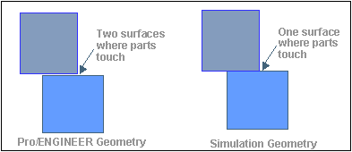
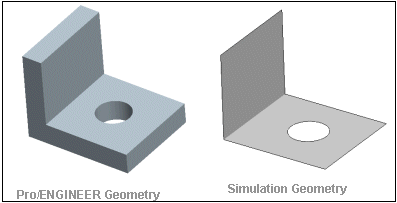
Creo Parametric represents the top level access to Creo Simulate geometry as an opaque handle called ProMechModel. The ProMechModel handle is generated upon request and can be accessed until it is freed by the application.
There are several modes which can be used to generate the model and its geometry:
|
• |
PRO_MECH_MODEL_SOLID signifies solid surfaces only. Shells will be ignored. |
|
• |
PRO_MECH_MODEL_SHELL signifies shell-compressed surfaces. Non shell-compressed surfaces will not be included. |
|
• |
PRO_MECH_MODEL_MIXED signifies both solid and shell-compressed surfaces. |
|
• |
PRO_MECH_MODEL_BOUNDARY signifies shell surfaces occurring on the solid boundary. |
|
• |
PRO_MECH_MODEL_QUILT signifies shell surfaces on quilts. This option requires that quilts be specified as additional entities to be processed. |
|
• |
PRO_MECH_MODEL_BAR signifies bars on given datum curves. This option requires that curves be specified as additional entities to be processed. |
It is not always necessary to have a Creo Simulate license to generate the Creo Simulate geometry. However, some situations do require the license:
|
• |
Use of the options PRO_MECH_MODEL_SHELL, PRO_MECH_MODEL_MIXED and PRO_MECH_MODEL_BOUNDARY is not permitted unless Creo Simulate is active. Please see the description for ProMechanicaIsActive() in the chapter Accessing Creo Simulate Items. |
|
• |
If any component of the model contains surface or volume region feature, Creo Simulate must be active to access the geometry of these regions. |
Functions Introduced:
Use the function ProMechmodeldataAlloc() to allocate an input data structure for generation of Creo Simulate geometry.
Use the function ProMechmodeldataTypeSet() to assign the type of model to be generated.
Use the function ProMechmodeldataEntitiesSet() to assign the additional datum points, quilts, and curves to be included in the geometric processing.
Use the function ProMechmodeldataPreserveidsSet() to set the preservation of IDs. In the event of the "Preserve IDs" flag being set, Creo Simulate tries to preserve the IDs of surfaces and edges in Creo Simulate geometry between different calls to ProMechmodelGet(). This happens even if the original geometry of the model has changed slightly, but the success of this attempt to preserve
geometry IDs is not always guaranteed.
Use the function ProMechmodeldataMergeCoincSolidEdgesSet() to set the flag that determines whether coincident solid edges will be merged. By default, the flag is PRO_B_FALSE, that is, the solid edges will not be merged.
Use the function ProMechmodelGet() to obtain the root handle of a Creo Simulate geometry model. The input arguments of this function are:
|
• |
solid—signifies the root solid model (part or assembly). |
|
• |
data—signifies the options for the generation of geometry. |
The output arguments are as follows:
|
• |
mech_model signifies the root handle of the generated geometry. |
|
• |
status signifies the status of generation and can have the following values:
|
○
|
PRO_MECH_MODEL_SUCCESS signifies success. |
|
○
|
PRO_MECH_MODEL_GENERAL_FAILURE signifies general failure. |
|
○
|
PRO_MECH_MODEL_USER_INTERRUPT signifies that the user interrupted the process before it completed. |
|
○
|
PRO_MECH_MODEL_SHELL_NO_PAIRS signifies that no shell pairs were defined (for options that used shell compression). |
|
○
|
PRO_MECH_MODEL_SHELL_SOME_PAIRS signifies that some paired and some unpaired surfaces exist.(for options that used shell compression). |
|
Use the function ProMechmodeldataFree() to free a data handle used for generation of a Creo Simulate geometry model. Use the function ProMechmodelFree() to free a Creo Simulate model handle. This invalidates all geometric entities obtained from this handle.
Accessing the ProMechSolid
An opaque handle called a ProMechSolid represents a solid volume member of the model (typically, an assembly member).
Functions Introduced:
The function types ProMechsolidVisitAction() and ProMechsolidFilterAction() are used as arguments to functions that visit ProMechSolid objects.
Use the function ProMechsolidIdGet() to obtain the ID of the solid volume. This ID is an index in the array of generated solid volumes and is not persistent among
different calls to ProMechmodelCreate().
Use the function ProMechsolidModelGet() to obtain the root Creo Simulate geometry model for this solid model.
Use the function ProMechsolidTypeGet() to obtain the solid volume type.
Use the function ProMechsolidAsmcomppathGet() to obtain the assembly component path from the top level assembly to this solid.
Use the function ProMechsolidSurfaceVisit() to visit the surfaces that are included in a given solid volume.
Use the function ProMechsolidEdgeVisit() to visit the edges that are included in a given solid volume.
Use the function ProMechsolidVertexVisit() to visit the vertices that are included in a given solid volume.
Accessing Creo Simulate ProMechSurface
An opaque handle called a ProMechSurface represents a Creo Simulate geometry surface. A surface can be of the following types:
|
• |
PRO_MECH_FACE_SOLID—A solid surface |
|
• |
PRO_MECH_FACE_SHELL—A shell (mid-plane) surface |
|
• |
PRO_MECH_FACE_SIDE—A shell side surface |
|
• |
PRO_MECH_FACE_SHELL_QLT—A quilt surface |
|
• |
PRO_MECH_FACE_BOUNDARY—A solid boundary surface |
|
• |
PRO_MECH_FACE_PERIM_WELD—A generated surface for a perimeter weld object |
Functions Introduced:
The function types ProMechsurfaceVisitAction() and ProMechsurfaceFilterAction() are used as arguments to functions that visit ProMechSurface objects.
Use the function ProMechsurfaceIdGet() to obtain the surface ID of the surface.
Note
This ID is not persistent and is not related to the Creo Parametric surface ID.
Use the function ProMechsurfaceOwnerGet() to obtain the owner ProMechsolid of the surface.
Use the function ProMechsurfaceTypeGet() to obtain the type of surface.
Use the function ProMechsurfaceContourVisit() to visit the contours that are included in a given surface.
Use the function ProMechsurfaceEdgeVisit() to visit the edges that are included in a given surface.
Use the function ProMechsurfaceVertexVisit() to visit vertices that are included in a given surface.
Use the function ProMechsurfaceAncestorsGet() to obtain the ancestor surfaces for the given surface. These are the actual Creo Parametric geometry surfaces used to construct this Creo Simulate surface.
Geometry Evaluation of ProMechSurface
Functions Introduced:
Use the function ProMechsurfaceParamEval() to find the corresponding UV point on the Creo Simulate geometry surface on the basis of the XYZ point.
Use the function ProMechsurfaceUvpntVerify() to verify whether the specified UV point lies within the boundaries of the Creo Simulate surface.
Use the function ProMechsurfaceTessellationGet() to calculate the tessellation for the provided Creo Simulate surface.
Use the function ProMechsurfaceDataGet() to obtain the geometric representation of the surface.
Use the function ProMechsurfaceToNURBS() to obtain the NURBS representation of the Creo Simulate surface.
Use the function ProMechsurfaceTransformGet() to obtain UV transform between the two surfaces in contact.
Use the function ProMechsurfaceThicknessEval() to obtain the thickness of the shell Creo Simulate surface at the given UV point.
Accessing ProMechContour
An opaque handle called a
ProMechContour represents a contour member of the model. See the
section on
Core: 3D Geometry for a discussion of contours.
Functions Introduced:
The function types ProMechcontourVisitAction() and ProMechcontourFilterAction() are used as arguments to functions that visit ProMechContour objects.
Use the function ProMechcontourIdGet() to obtain the ID for a given contour. This ID is unique within the surface that owns the contour.
Use the function ProMechcontourSurfaceGet() to obtain the surface that contains the contour.
Use the function ProMechcontourTraversalGet() to obtain the contour traversal.
Use the function ProMechcontourEdgeVisit() to visit the edges that make up a contour.
Use the function ProMechcontourUvpntVerify() to verify whether the specified UV point lies within the given Creo Simulate contour.
Use the function ProMechcontourAreaEval() to find the surface area inside the given outer contour, accounting for internal voids.
The function ProMechcontourContainingContourGet() returns the containing contour for a Creo Simulate contour object.
Accessing ProMechEdge
An opaque handle called a ProMechEdge represents an edge member of the model.
Functions Introduced:
The function types ProMechedgeVisitAction() and ProMechedgeFilterAction() are used as arguments to functions that visit ProMechEdge objects.
Use the function ProMechedgeIdGet() to obtain the ID of the given edge.
Note
This ID is not persistent and is not related to the Creo Parametric edge ID.
Use the function ProMechedgeOwnerGet() to obtain the owner ProMechSolid of the given edge.
Use the function ProMechedgeSurfaceVisit() to visit the surfaces that share this edge.
Use the function ProMechedgeContourVisit() to visit the contours that contain this edge.
Use the function ProMechedgeEndpointsGet() to obtain the endpoints of the given edge.
Use the function ProMechedgeIncontactedgesGet() to obtain the list of edges that are in contact with the given edge.
Use the function ProMechedgeAncestorsGet() to obtain the ancestor edges for the given edge. These are the actual Creo Parametric geometry edges used to construct this Creo Simulate edge.
Geometry Evaluation of ProMechEdge
Functions Introduced:
Use the function ProMechedgeUvdataEval() to evaluate the Creo Simulate edge in the UV space of the given surface.
Use the function ProMechedgeXyzdataEval() to evaluate the Creo Simulate edge parameter point in XYZ space.
Use the function ProMechedgeParamEval() to find the corresponding normalized parameter on the Creo Simulate edge by XYZ point.
Use the function ProMechedgeLengthEval() to obtain the length of the edge.
Use the function ProMechedgeLengthT1T2Eval() to find the length of the Creo Simulate edge between the given parameters.
Use the function ProMechedgeParamByLengthEval() to find the parameter of the point located at the given length from the given parameter.
Use the function ProMechedgeTessellationGet() to get the edge tessellation for the Creo Simulate edges.
Use the function ProMechedgeToNURBS() to obtain the NURBs representation of the Creo Simulate edge.
Use the function ProMechedgeReldirGet() to obtain the relative direction of two Creo Simulate edges in contact.
Use the function ProMechedgeDataGet() to obtain the geometric representation of the edge.
Use the function ProMechedgeDirectionGet() to obtain the edge direction with respect to the given contour.
Accessing ProMechPoint
An opaque handle called a ProMechPoint represents a datum point member of the model. By default, the Creo Simulate geometry will include only those points which have Creo Simulate loads or other items referencing them; you can generate additional points by including them as inputs to ProMechmodeldataEntitiesSet().
Functions Introduced:
The function types ProMechpointVisitAction() and ProMechpointFilterAction() are used as arguments to functions that visit ProMechPoint objects.
Use the function ProMechpointIdGet() to obtain the ID of the point.
Note
This ID is not persistent and is not related to the Creo Parametric point ID.
Use the function ProMechpointOwnerGet() to obtain the owner model of the given point.
Use the function ProMechpointPointGet() to obtain the coordinates of the point.
Use the function ProMechpointPlacementtypeGet() to obtain the placement type for the point. Following are list of possible placement types:
|
• |
PRO_MECH_PNT_FREE signifies that the point is not attached to a solid or shell. |
|
• |
PRO_MECH_PNT_FACE signifies that the point lies on a ProMechSurface. |
|
• |
PRO_MECH_PNT_EDGE signifies that the point lies on a ProMechEdge. |
|
• |
PRO_MECH_PNT_VERTEX signifies that the point lies on a ProMechVertex. |
Use the function ProMechpointPlacementsurfaceGet() to obtain the placement surface, if the placement type is PRO_MECH_POINT_FACE.
Use the function ProMechpointPlacementedgeGet() to obtain the placement edge, if placement type is PRO_MECH_POINT_EDGE.
Use the function ProMechpointPlacementvertexGet() to obtain the placement vertex, if the placement type is PRO_MECH_POINT_VERTEX.
Use the function ProMechpointAncestorsGet() to obtain the ancestor points for the given point. These are the actual Creo Parametric geometry points used to construct this Creo Simulate point.
Accessing ProMechCompositeCurve
An opaque handle called a ProMechCompositeCurve represents a composite curve member of the model. By default, the Creo Simulate geometry will include only those curves which have Creo Simulate loads or other items referencing them. You can generate additional curves by including them as inputs to ProMechmodeldataEntitiesSet().
Functions Introduced:
The function types ProMechcompositecurveVisitAction() and ProMechcompositecurveFilterAction() are used as arguments to functions that visit ProMechCompositeCurve objects.
Use the function ProMechcompositecurveIdGet() to obtain the ID of the composite curve.
Note
This ID is not persistent and is not related to the Creo Parametric composite curve ID.
Use the function ProMechcompositecurveOwnerGet() to obtain the owner model of the composite curve.
Use the function ProMechcompositecurveCurveVisit() to visit the curves that make up this composite curve.
Use the function ProMechcompositecurveAncestorsGet() to obtain the ancestor curves for the given curve. These are the actual Creo Parametric geometry curves used to construct this Creo Simulate curve.
Accessing ProMechCurve
An opaque handle called a ProMechCurve represents a curve member of the model. A curve is always the child of a composite curve.
Functions Introduced:
The function types ProMechcurveVisitAction() and ProMechcurveFilterAction() are used as arguments to functions that visit ProMechCurve objects.
Use the function ProMechcurveTypeGet() to obtain the curve's type. Curves may be of the following types:
|
• |
PRO_MECH_SEGMENT_ON_EDGE |
Use the function ProMechcurveEdgeGet() to obtain the edge, if the curve type is PRO_MECH_CURVE_EDGE.
Use the function ProMechcurveParentGet() to obtain the parent composite curve for this curve.
Use the function ProMechcurveParamGet() to obtain the parameter along the parent composite curve at which this curve begins.
Use the function ProMechcurveEndpointsGet() to obtain the endpoints of the curve.
Use the function ProMechcurveAncestorsGet() to obtain the ancestor curves for the specified Creo Simulate curve. The ancestor curves are the actual Creo Parametric geometry curves used to construct the Creo Simulate curve.
Geometry Evaluation of ProMechCurves
Functions Introduced:
Use the function ProMechcurveXyzdataEval() evaluates the Creo Simulate curve parameter point in the XYZ point.
Use the function ProMechcurveParamEval() to find the corresponding normalized parameter on the Creo Simulate curve by XYZ point.
Use the function ProMechcurveLengthEval() to obtain the length of the curve.
Use the function ProMechcurveLengthT1T2Eval() to find the length of the Creo Simulate curve between the given parameters.
Use the function ProMechcurveParamByLengthEval() to find the parameter of the point located at the given length from the given parameter.
Use the function ProMechcurveDataGet() to obtain the geometric representation of the edge.
Use the function ProMechcurveToNURBS() to obtain the NURBS representation of the Creo Simulate curve.


