Production Applications: Manufacturing
This section describes the Creo TOOLKIT functions for manufacturing operations. Familiarity with Creo NC functions simplifies the use of these manufacturing functions.
Manufacturing Models
Functions Introduced:
You can use the function ProSolidFeatVisit() to visit all the components in a manufacturing model. However, this function requires a ProSolid (or one of its instances, ProPart or ProAssembly) handle to the model as input. The function ProMfgAssemGet() outputs a ProAssembly handle to the top-level assembly in the manufacturing model, given its ProMfg handle. This assembly handle can then be passed to ProSolidFeatVisit().
Manufacturing models, like other models in Creo Parametric, are uniquely identified by name and type. However, there are several different varieties of manufacturing models. For example, assembly machining, sheetmetal manufacturing, and mold manufacturing are all types of manufacturing models. The ProMfg object is a general purpose, opaque handle used to represent any of the different manufacturing model varieties. To distinguish between the different types of manufacturing model, there are manufacturing subtypes. The complete list of subtypes is as follows:
•  PRO_MFGTYPE_MACH_ASSEM
•  PRO_MFGTYPE_SHEET_METAL
•  PRO_MFGTYPE_MOLD
•  PRO_MFGTYPE_CAST
•  PRO_MFGTYPE_CMM
The function ProMfgTypeGet() outputs the subtype, given the ProMfg handle to the manufacturing object.
Creating a Manufacturing Model
Function Introduced
The function ProMfgMdlCreate() outputs an initialized ProMfg object handle, given the model name, manufacturing subtype, and name of the reference model. For sheetmetal manufacturing, this should be the sheetmetal workpiece. For all other subtypes, the reference model argument is ignored.
Analyzing a Manufacturing Model
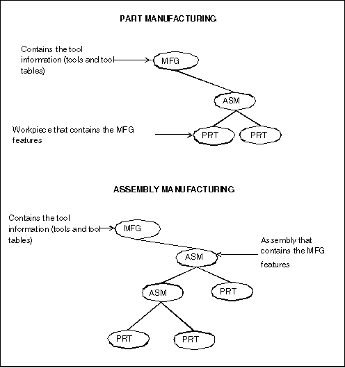
Creo NC has two modes of operation—part and assembly manufacturing. In both cases, the top-level model is an assembly that contains the description of the tools. The following diagram shows the hierarchy of part and assembly manufacturing models.
Part and Assembly Manufacturing Model Hierarchy
Image
In part manufacturing, the storage solid is a part that represents the workpiece or stock, and the design piece is another component at the same level. In assembly manufacturing, the storage solid is the actual assembly representing the design model. The workpiece can be at any level inside this assembly. In both types of manufacturing, the manufacturing operations are described as features of the storage solid.
The important tasks for Creo TOOLKIT are to traverse the manufacturing assembly components, identify the storage solid that contains the manufacturing operations as its features, and list the manufacturing tools.
This section contains the following subsections:
Traversing Manufacturing Components
Function Introduced:
You can visit the components in a manufacturing assembly using the same functions that enable you to visit the components of a regular assembly. For a full description of these functions, see Assembly: Basic Assembly Access .
The components within a manufacturing assembly perform a variety of different roles. The function ProAsmcompTypeGet() provides the role of any model under a manufacturing assembly. The possible roles are as follows:
•  PRO_ASM_COMP_TYPE_NONE—A regular component (no special manufacturing role)
•  PRO_ASM_COMP_TYPE_WORKPIECE—A workpiece
•  PRO_ASM_COMP_TYPE_REF_MODEL—A reference model
•  PRO_ASM_COMP_TYPE_FIXTURE—A fixture
•  PRO_ASM_COMP_TYPE_MOLD_BASE—A mold base
•  PRO_ASM_COMP_TYPE_MOLD_COMP—A mold component
•  PRO_ASM_COMP_TYPE_MOLD_ASSEM—A mold assembly
•  PRO_ASM_COMP_TYPE_GEN_ASSEM—A general assembly
•  PRO_ASM_COMP_TYPE_CAST_ASSEM—A cast assembly
•  PRO_ASM_COMP_TYPE_DIE_BLOCK—A die block
•  PRO_ASM_COMP_TYPE_DIE_COMP—A die component
•  PRO_ASM_COMP_TYPE_SAND_CORE—A sand core
•  PRO_ASM_COMP_TYPE_CAST_RESULT—A cast result
Identifying the Storage Solid
Functions Introduced:
Another important task in using Creo TOOLKIT for accessing Creo NC models is to find the storage solid inside the manufacturing model. This model is important because the manufacturing operations—workcells, NC sequences, and so on—are represented as features within it.
Manufacturing features are treated like all other features in Creo TOOLKIT. This enables you to search for NC sequences as you would for solid features. For example, to visit all the workcells of a manufacturing solid, you can use the ProSolidFeatVisit()function and filter out any model items not of type PRO_E_WCELL.
The function ProMfgSolidGet() returns the handle to the storage solid, and ProMfgFeatureOwnerGet() returns the component path to the solid from the top-level assembly.
Example 1: Identifying Workcell Features of a NC Model
The sample code in UgMfgWcellIdentify.c located at <creo_toolkit_loadpoint>/protk_appls/pt_userguide/ptu_mfg shows how to identify workcell features.
Visiting Manufacturing Tools
Functions Introduced:
Tools are not stored as features of the manufacturing solid, nor as components in the assembly; they are special objects within the top-level manufacturing model, so they need their own visit function. This function is ProMfgToolVisit(), which has the same form as other visit functions in Creo TOOLKIT, except it does not offer the option of a user-defined filter function. You call the action function with an input argument of type ProTool to identify the tool.
The other functions analyze the tool being visited.
The function ProToolTypeGet() returns the tool type. Examples of the types are as follows:
•  PRO_TOOL_DRILL
•  PRO_TOOL_TURN
•  PRO_TOOL_SAW
•  PRO_TOOL_MILL
The ProToolModelMdlnameGet() function outputs the model name and type of a tool, given its ProTool handle.
The function ProToolParamGet() retrieves the value of a specified tool parameter. This yields a value in terms of the type ProParamvalue (see the Core: Parameters for more information).
The function ProToolAttributesGet() provides the current setting of several Boolean attributes of the tool in the form of an integer bitmap. Currently, the attributes define whether a solid tool is to be by reference or by copy. See the section Creating NC Sequences for more information on creating tools.
The function ProToolVerify() returns a Boolean showing whether a specified tool handle corresponds to an existing tool.
Creating Manufacturing Objects
This section explains how to create all types of manufacturing feature. This section assumes you have an understanding of element trees for feature creation and Creo NC. For an introduction to element trees, see Element Trees: Principles of Feature Creation.
Note
You must have a Creo NC license to create manufacturing features using Creo TOOLKIT.
An important principle of creating manufacturing features is that all the elements required to be defined interactively must also be defined when you create that feature using Creo TOOLKIT.
As with creating solid features, manufacturing features use element trees to define the feature before you call ProFeatureCreate() to create the feature. However, the method of creating tools is slightly different, as described in the following sections.
Creating Tools
Functions Introduced:
In Creo Parametric, and therefore in Creo TOOLKIT, tools are not features, and must be created in a slightly different manner for solid and manufacturing features.
Tool creation involves initializing an input structure using a call to ProToolinputAlloc().
You set the tool type (for example, center drill or ream) directly in the input structure using the function ProToolinputTypeSet().
You can then add tool elements to this input structure using a three-step process. First, initialize each element using the function ProElementAlloc(). Next, add data to this element using an element-specific function. Finally, add the element to the tool input structure using ProToolinputElemAdd().
As in Creo Parametric, tools can be defined by parameter or by model. To add a parameter to a tool, first allocate the space for a parameter element using a call such as this:
status = ProElementAlloc (PRO_E_PARAM, &element);
Next, add the parameter to the element using the function ProToolElemParamAdd(), then add the element itself to the input structure using the function ProToolinputElemAdd().
The following table lists the parameters required to be defined for each turning tool.
Parameter
Turn
Turn Groove
NOSE_RADIUS
TOOL_WIDTH
SIDE_WIDTH
LENGTH
SIDE_ANGLE
END_ANGLE
GAUGE_X_LENGTH
GAUGE_Z_LENGTH
TOOL_MATERIAL
HOLDER_TYPE
The following table lists the parameters required to be defined for milling tools.
Parameter
Mill
Side Mill
Thread Mill
Groove
CUTTER_DIAM
CORNER_RADIUS
CUTTER_WIDTH
SHANK_DIAM
LENGTH
INSERT_LENGTH
END_OFFSET
SIDE_ANGLE
GAUGE_X_LENGTH
GAUGE_Z_LENGTH
NUM_OF_TEETH
TOOL_MATERIAL
The following table lists the parameters required to be defined for auxiliary and contouring tools.
Parameter
Auxiliary
Contouring
CUTTER_DIAM
LENGTH
The following table lists the parameters required to be defined for holemaking tools.
Parameter
Drill
Csink
Tap
Ream
Center Drill
Bore
BackSpot
CUTTER_DIAM
POINT_DIAMETER
DRILL_DIAMETER
BODY_DIAMETER
LENGTH
CHAMFER_LENGTH
DRILL_LENGTH
INSERT_LENGTH
TIP_OFFSET
GAUGE_OFFSET
CUTTING_OFFSET
SIDE_ANGLE
POINT_ANGLE
CSINK_ANGLE
GAUGE_X_LENGTH
GAUGE_Z_LENGTH
TOOL_MATERIAL
Refer to the Creo Parametric NC Manufacturing Help for more information.
Creating a tool using a tool model is similar to the previous process. First, allocate space for an element of type PRO_E_TOOL_MODEL. Set the model in the element using the function ProToolElemModelSet(), then add it to the input structure using ProToolinputElemAdd(). As in Creo NC, you must specify the required number of dimensions within the tool model.
Creating the tool requires two steps. First, initialize a tool handle using ProToolInit(). This creates a tool identifier that uniquely defines the tool and is used to reference that tool within the manufacturing model. You pass this identifier, together with the completed input structure, to the function ProToolCreate(), which actually creates the tool.
Once the tool has been created, release the memory used by the tool input structure and its associated elements using the function ProToolinputFree().
The following table shows the elements required for tool creation. In this table, the Value column specifies whether the element is required (R) or optional (O).
Element
Description
Value
Name
The name used to identify the tool
R
Type
Mill, drill, and so on
R
Parameters (for parameter-driven tools only)
Tool parameters
R
Model (for solid tools only)
Model that represents the tool
R
The function ProToolFileRead() creates a new tool or redefines an existing tool. The input arguments for this function are as follows:
•  tool_handle—Specify the handle to the tool to be created or redefined.
•  input_file—Specify the full path and name of the input file that contains all the parameter information about the tool to be created or redefined.
The function ProToolFileWrite() writes all information about the tool into a file. Pass the following as input arguments to this function:
•  tool_handle—Specify the handle to the tool whose information is to be saved.
•  output_file—Specify the full path and name of the output file where the tool information is to be saved.
Example 2: Creating a Tool from a Solid Model
The sample code in UgMfgSldToolCreate.c located at <creo_toolkit_loadpoint>/protk_appls/pt_userguide/ptu_mfg shows how to create a tool from solid model.
Example 3: Creating a Parameter-Driven Tool
The sample code in UgMfgParamToolCreate.c located at <creo_toolkit_loadpoint>/protk_appls/pt_userguide/ptu_mfg shows how to create a drilling tool from parameters.
Example 4: Creating a Milling Workcell
The sample code in UgMfgWcellCreate.c located at <creo_toolkit_loadpoint>/protk_appls/pt_userguide/ptu_mfg shows the process to create a milling workcell. Copy the mill_d20.xml file from <creo_toolkit_loadpoint>/protk_appls/models/mfg to your working directory to create a workcell using the sample code.
Manufacturing Parameters
In general, there are a number of parameters that are mandatory for a given tool type or NC sequence, and others that are optional. For example, a milling tool requires that its length and diameter be specified, while other parameters such as the number of teeth, or tool material are optional.
The addition of manufacturing parameters to both workcells and operations is optional.
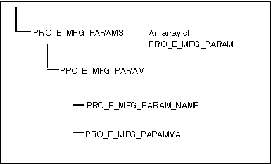
The following figure shows a parameter element subtree.
Parameter Element Subtree
Image
The process of creating a parameter element subtree is the same for workcells, operations, and NC sequences. First, allocate the space for the PRO_E_MFG_PARAMS array element. The simplest method of creating the tree is to delay adding the PRO_E_MFG_PARAMS element to its parent until you have fully defined the tree. As you define each PRO_E_MFG_PARAM element, add it to the PRO_E_MFG_PARAMS array using ProElemtreeElementAdd(). Use NULL for the element path as each PRO_E_MFG_PARAM element is added to the parameter element tree.
The PRO_E_MFG_PARAM element itself is a compound element and requires two children to be defined. One is the PRO_E_MFG_PARAM_NAME element, a string (not a wide string) that represents the parameter name to define. The other is a PRO_E_MFG_PARAMVAL element, which represents the value of the parameter. Depending on the context, this might be an integer, double, or wide string. For example, CUT_FEED is represented by a double, whereas NUMBER_OF_ARC_PNTS is an integer. Refer to the Creo Parametric NC Manufacturing Help for more information on manufacturing parameters.
Example 4: Creating a Parameter Tree
The sample code in UgMfgParamTreeCreate.c located at <creo_toolkit_loadpoint>/protk_appls/pt_userguide/ptu_mfg shows how to create a parameter element tree.
Using External Functions to Define Parameters in the Manufacturing Step Table
Creo TOOLKIT provides the capability to define customized functions that are available from within the Relations user interface and can be used to define relations for a given item. This capability is described in the section Adding a Customized Function to the Relations Dialog in Creo Parametric in Core: Relations. External relation functions can also be used within relations stored in steps in the Manufacturing Step Table.
External functions can be used to define new parameters for the members of the step table. For example, if a parameter 'sample_parameter' is defined as follows:
sample_parameter = protk_user_defined_function (list of arguments)
The definition suggests that the value of the parameter sample_parameter is set as a result of the calculation done using the function protk_user_defined_function.
The following steps are required to define new parameters using external relation functions:
1. Within the Creo TOOLKIT application, register an appropriate external function using ProRelationFunctionRegister().
2. In the user interface for the step table, define the relation calling the externally registered functions.
Creo TOOLKIT relation functions called from an entry in the Step Table will have one of two owners for the relation set (ProRelSet) depending on the following cases:
Case 1: If the step has been applied
The owner will be the manufacturing feature created by this step table entry.
Case 2: If the step has not been applied
The owner will be an object whose type is PRO_NC_STEP_OBJECT.
Using external functions, it is possible to interact with an external database or application, in order to set the value of some parameters in the Process Table. Because relations may be reevaluated many times during a regeneration cycle, PTC recommends that the external functions contain some control that prevents reconnection to the external database on each invocation.
Note
If no Creo TOOLKIT application has registered the needed external function, any relation using the function cannot be evaluated and is shown as an error. However, when defining Global Relations, even if an undefined function is encountered, the relation will pass the validation, but, the relation will not be applied to the steps because the function is not found.
Creating Manufacturing Features
The creation of manufacturing features mirrors the creation of solid features in Creo TOOLKIT. All features at the very least must define a feature type. Certain manufacturing features also have a requirement that some “non-redefinable” elements must be defined.
With the exception of fixtures, all features are created in the manufacturing solid. However, fixtures are owned by the manufacturing assembly.
Like solid feature creation, manufacturing feature creation consists of several distinct steps:
1. Create the feature element tree.
2. Add nodes or subtrees to the feature tree.
3. Create a selection that represents the model in which to construct the feature.
4. Create the feature.
The following sections document only the first two steps for manufacturing features, because the actual process of feature creation is common to all.
Creating Fixtures
A fixture setup feature is one of the simplest manufacturing features and contains a maximum of four elements.
You should name a fixture setup feature. Optionally, you can define the following:
•  The time required to perform the setup
•  The identifiers of the fixturing components
•  Associated comments
To Create an Element Tree for a Fixture Setup Feature
1. Allocate space for the tree using the following call:
       ProElementAlloc (PRO_E_FEATURE_TREE);
2. Define the feature type element (PRO_E_FEATURE_TYPE) to be an integer of value PRO_FEAT_FIXSETUP.
3. Define the name (PRO_E_FEAT_NAME) to be a wide string.
4. Optionally, add the setup time (PRO_E_SETUP_TIME) as a double.
5. Optionally, add the component identifiers of the fixturing models (PRO_E_FIXT_COMPONENTS).
Note
Because this is a multivalue element, you can add multiple (integer) values to the PRO_E_FIXT_COMPONENT element.
When the tree is complete, you can pass it (and a selection handle that represents the manufacturing assembly) to the function ProFeatureCreate().
Creating Workcells
The element tree for workcells is described in the include file ProWcell.h. For this feature, the feature type element is PRO_FEAT_WORKCELL.
The following table shows the required and optional elements for workcell features. In this table, the “Value” column specifies whether the element is required (R) or optional (O).
Element
Description
Value
Cell type
Mill, mill/turn, and so on.
R
Number of axes
The number of axes.
R
Table direction
Horizontal or vertical (for turn or mill/turn)
R
Machine number heads
1 or 2 (for turn or mill/turn)
R
Name
The workcell name.
O
Tooling
Add tools to the workcell.
O
Tool table
Manipulate the tools in a tool table.
O
Parameters
The workcell parameters.
O
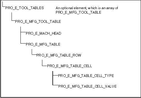
The feature element has two complex elements—PRO_E_MFG_PARAMS, described in the section Manufacturing Parameters, and PRO_E_TOOL_TABLE. The following figure shows how the tool table element is constructed.
Tool Table Element
Image
The first thing to note is that a workcell can have multiple tool tables, if it has more than one machine head. In this case, you can create a tool table for each head.
A manufacturing table is made up of an array of PRO_E_MFG_TABLE_ROW elements, which is itself an array of PRO_E_MFG_TABLE_CELL elements. Each PRO_E_MFG_TABLE_CELL is a compound element that contains two more elements—the cell type and its value.
The following examples show how to create a tool table with five drill bits, ranging in size from M8 to M16. The tool table for most workcells (excluding CMM) is of the following format:
   POSITION   TOOL_ID   REGISTER  COMMENTS
   1          drill_M8            8MM Drill
   2          drill_M10           10MM Drill
For example, to create the first row of the table, you would define the following PRO_E_MFG_TABLE_CELLs:
•  To define the first cell so the position of the tool is index 1, set the value of the PRO_E_MFG_TABLE_CELL_TYPE to PRO_TOOL_TABLE_INDEX, and set the value of PRO_E_MFG_TABLE_CELL_VALUE to the integer value 1.
•  Similarly, define the tool identifier to be a drill_M8. Set the cell type element to PRO_TOOL_TABLE_TOOL_ID, and set the value to a wide string of value drill_M8. Because the register column is empty, it can be ignored. To set the comments element, set the type to PRO_TOOL_TABLE_COMMENTS, and set the value to a wide string of value “8MM Drill.”
Example 5: Creating a 2-Axis Lathe Workcell
The sample code in UgMfgWcellCreate.c located at <creo_toolkit_loadpoint>/protk_appls/pt_userguide/ptu_mfg shows how to set up a simple 2-axis, horizontal lathe, using the previously created tool table. Note that both the PRO_E_LATHE_DIR and PRO_E_MACH_NUM_HEADS are required for this workcell type. All the other elements are optional.
Creating Operations
The element tree for manufacturing operations is described in the header file ProMfgoper.h. For this feature, the feature type element is PRO_FEAT_WORKCELL.
The following table shows the elements of a manufacturing operation. In this table, the “Value” column specifies whether the element is required (R) or optional (O).
Element
Description
Value
Workcell
The identifier of the workcell feature in which to perform the operation
R
Machine coordinate system
The identifier of the machining coordinate system
R
Name
The operation name
O
Comments
The operation comments
O
From point
The datum point from which to start the operation
O
Home point
The datum point on which to end the operation
O
Parameters
The operation parameters
O
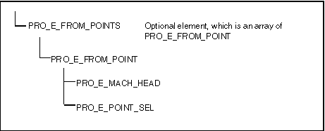
The creation of the feature tree is simple, apart from the home and point elements. The following figure shows the element tree for the home points.
Home Point Element Tree
Image
In this example, there is a from and home point defined for each machining head. If there is only one head, the value of the PRO_E_MACH_HEAD element should be 1. Note that the PRO_E_POINT_SEL selection should be initialized not to the datum point feature, but to the datum point geometry. To find this geometry, call the function ProFeatureGeomitemVisit()).
Example 6: Creating an Operation
The sample code in UgMfgOperCreate.c located at <creo_toolkit_loadpoint>/protk_appls/pt_userguide/ptu_mfg shows how to create an operation.
Creating NC Sequences
Header file ProNcseq.h describes the element tree for manufacturing NC sequences.
There are supported NC sequence types:
•  PRO_NCSEQ_PROF_SUR_MILL—Profile milling, feature type PRO_FEAT_MILL
•  PRO_NCSEQ_VOL_MILL—Volume milling, feature type PRO_FEAT_MILL
•  PRO_NCSEQ_CONV_SURF_MILL—Conventional surface, feature type PRO_FEAT_MILL
•  PRO_NCSEQ_FACE_MILL—Face milling, feature type PRO_FEAT_MILL
•  PRO_NCSEQ_PREV_TOOL_MILL—Local milling using previous tool, feature type PRO_FEAT_MILL
•  PRO_NCSEQ_HOLEMAKING—Holemaking, type PRO_FEAT_DRILL
•  PRO_NCSEQ_MW_ROTARY_FINISH_MILLING—High speed milling PRO_FEAT_MILL
Like workcells, an NC sequence feature has a number of non-redefinable elements. For all NC sequences, the PRO_E_NCSEQ_TYPE and PRO_E_NUM_AXES elements are non-redefinable. For holemaking sequences, the PRO_E_HOLEMAKING_TYPE, PRO_E_PECK_TYPE, and PRO_E_HOLE_CYCLE_TYPE elements are non-redefinable. These elements are specific to holemaking sequences and need not be defined for milling sequences. The following table shows the elements of an NC sequence. In this table, the Value column specifies whether the element is required (R) or optional (O).
Element
Description
Value
Feature type
The feature type
R
Type
The sequence type
R
Operation
Operation to which to add the NC sequence
R
Retraction plane
The retraction plane
R
Tool
The tool
R
Csys
The manufacturing coordinate system
R
Parameters
The manufacturing parameters
R
Name
The name of the NC sequence
O
Number of axes
The number of axes
O
Machine head
The machine head
O
Fixture
The fixture
O
Entities to be machined
Surface
The surface
R
Holes or volume
The holes or volume
R
Start path
The start path
R
End path
The end path
R
The retraction plane that must be defined as part of the NC sequence requires the identifier of the underlying geometry of the datum plane. To obtain this identifier, visit the datum plane geometry items using ProFeatureGeomitemVisit().
There are also a number of required parameters for each NC sequence that must be defined. For conventional milling, the following parameters are required:
•  CUT_FEED
•  TOLERANCE
•  STEP_OVER
•  SPINDLE_SPEED
•  CLEAR_DIST
For face milling, the following parameters are required:
•  CUT_FEED
•  STEP_DEPTH
•  TOLERANCE
•  STEP_OVER
•  SPINDLE_SPEED
•  CLEAR_DIST
For holemaking, the following parameters are required:
•  CUT_FEED
•  TOLERANCE
•  SPINDLE_SPEED
•  CLEAR_DIST
Both milling and holemaking features elements require that the entities (and some associated properties) to be machined are set by API functions, rather than by element tree. Like the standard elements, these functions require a call to ProElementAlloc() to reserve space for the elements. Once the elements are complete, you can add them to the tree like the other standard elements.
Note
Currently, using ProFeatureElemtreeExtract()with NC sequences yields an element tree without holes or surface elements. In other words, there is no way to retrieve hole set or surface information.
Milling-Specific Functions
Functions Introduced:
After you allocate the surface element with ProElementAlloc(), you can add the surface to be milled to the element using the function ProNcseqElemSurfaceAdd().
If the model contains a milling surface, you can set the whole surface in the NC sequence using ProNcseqElemMillsurfSet(). To control its orientation, call ProNcseqElemSurfaceflipSet().
Example 7: Adding Surfaces
The sample code in UgMfgSrfAdd.c located at <creo_toolkit_loadpoint>/protk_appls/pt_userguide/ptu_mfg shows how to use the function ProNcseqElemSurfaceAdd().
Holemaking-Specific Functions
To add hole sets to an element tree, first, obtain the hole set number by calling the function ProNcseqElemHolesetAdd(). This hole set is used to reference a set of holes with the same properties, including depth, direction, countersink diameter, and so on. Note that feature element PRO_E_HOLESETS has limited support for drill point sets, but allows the user to identify and to delete existing drill point sets in a feature, or to overwrite drill point sets with drill axes sets.
For example, you might want one set of holes to be countersunk to a diameter of 10mm, and another set to 14mm. Because these countersinking operations are done with the same tool, they should be in the same NC sequence. Because the countersink diameter is different for each, you should create two hole sets.
Note
The following functions (and the element tree PRO_E_HOLES) exist in Pro/TOOLKIT Revisions 20 and later only to provide backwards compatibility. Use the more complete and powerful element tree PRO_E_HOLESETS for holemaking functions.
•  ProNcseqElemHolesetAdd()
•  ProNcseqElemHolesetDepthTypeSet()
•  ProNcseqElemHolesetDepthBySet()
•  ProNcseqElemHolesetDepthSet()
•  ProNcseqElemHolesetStartSet()
•  ProNcseqElemHolesetEndSet()
•  ProNcseqElemHolesetDirectionSet()
•  ProNcseqElemHolesetAxisAdd()
•  ProNcseqElemHolesetDrillpartAdd()
•  ProNcseqElemHolesetCsinkdiamSet()
Creating Material Removal Volumes
In Creo Parametric, material removal features can be created by defining geometry to represent the volume removed, or they can be calculated automatically from the NC sequence. The current release of Creo TOOLKIT supports automatic material removal feature creation only.
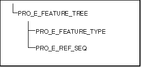
The feature tree is very simple, as shown in the following figure.
Feature Tree
Image
Set the PRO_E_FEATURE_TYPE value to PRO_FEAT_MAT_REMOVAL, and set the PRO_E_REF_SEQ to the identifier of the NC sequence feature from which to create the material removal volume.
Example 8: Creating a Conventional Milling Sequence
The sample code in UgMfgMillSeqCreate.c located at <creo_toolkit_loadpoint>/protk_appls/pt_userguide/ptu_mfg shows how to create a milling feature using an element tree.
Analyzing Manufacturing Features
Functions Introduced:
You can use the functions ProMfgoperToolpathDisplay() and ProNcseqToolpathDisplay() to invoke the corresponding toolpath for the specified object. The function ProNcseqNumGet() returns the number of the specified NC sequence.
The final two functions access the machining time and the volume of material removed during the machining sequence.