Element Trees: Hole
This section describes the programmatic creation of Hole features using the Creo TOOLKIT include file ProHole.h.
We recommend you read the section, Overview of Feature Creation in the section, Element Trees: Principles of Feature Creation It provides the necessary background for creating features using Creo TOOLKIT.
Overview
Creo TOOLKIT supports four types of Holes:
•  Straight
•  Standard
•  Sketched
•  Custom
The Standard Hole type is sub-divided into two categories:
•  Standard Clearance Hole
•  Standard Threaded Hole
This section details the procedure and the sequence of the creation of the element tree for all of the above types.
All Hole types and placement types require entry of specific elements during element tree creation. Elements must be entered in the specified order.
To create a Hole feature, first add to the element tree all elements related to the hole type. Then, add the elements required for Hole placement. Creating Sketched Holes uses techniques similar to creation of the other sketched features (see Element Trees: Sketched Features).
Note
All angle elements are specified in degrees.
You can use Intent Datums such as Intent Point, Intent Axis, and Intent Plane for hole placement in parts.
Lightweight holes can be created only in parts and not in assemblies. You can toggle between a lightweight and regular hole, only in case of simple holes and not in sketched, standard, or custom holes.
Feature Element Tree for Hole Features
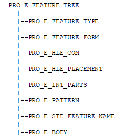
The element tree for the Hole feature is documented in the Creo TOOLKIT header file ProHole.h.
Feature Element Tree for Hole Feature
Image
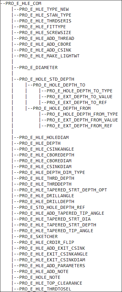
Common Elements for Hole Types
Image
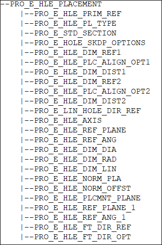
Common Elements for Hole Placement
Image
Feature Element Data Types
The following table lists data types for hole type and placement elements.
Element values must be of the specified type.
Hole Element Table
Element Id
Element Name
Data Type
PRO_E_FEATURE_TYPE
Feature Type
PRO_VALUE_TYPE_INT
PRO_E_FEATURE_FORM
Feature Form
PRO_VALUE_TYPE_INT
PRO_E_HLE_COM
Hole
Compound
PRO_E_HLE_TYPE_NEW
Hole Type
PRO_VALUE_TYPE_INT
PRO_E_HLE_STAN_TYPE
Standard Type
PRO_VALUE_TYPE_INT
PRO_E_HLE_THRDSERIS
Thread Series
PRO_VALUE_TYPE_INT
PRO_E_HLE_FITTYPE
Fit Type
PRO_VALUE_TYPE_INT
PRO_E_HLE_SCREWSIZE
Screw Size
PRO_VALUE_TYPE_INT
PRO_E_HLE_ADD_THREAD
Add Thread
PRO_VALUE_TYPE_INT
PRO_E_HLE_ADD_CBORE
Add Counterbore
PRO_VALUE_TYPE_INT
PRO_E_HLE_ADD_CSINK
Add Countersink
PRO_VALUE_TYPE_INT
PRO_E_HLE_MAKE_LIGHTWT
Make lightweight hole
PRO_VALUE_TYPE_INT (It is given by the enumerated type ProHleLightWtFlag)
PRO_E_DIAMETER
Diameter
PRO_VALUE_TYPE_DOUBLE
PRO_E_HOLE_STD_DEPTH
Depth Element
Compound
PRO_E_HOLE_DEPTH_TO
Depth Two
Compound
PRO_E_HOLE_DEPTH_TO_TYPE
Depth Two
PRO_VALUE_TYPE_INT
PRO_E_EXT_DEPTH_TO_VALUE
Depth Value
PRO_VALUE_TYPE_DOUBLE
PRO_E_EXT_DEPTH_TO_REF
Reference
PRO_VALUE_TYPE_SELECTION
PRO_E_HOLE_DEPTH_FROM
Depth One
Compound
PRO_E_HOLE_DEPTH_FROM
_TYPE
Depth One
PRO_VALUE_TYPE_INT
PRO_E_EXT_DEPTH_FROM
_VALUE
Depth Value
PRO_VALUE_TYPE_DOUBLE
PRO_E_EXT_DEPTH_FROM_REF
Reference
PRO_VALUE_TYPE_SELECTION
PRO_E_HLE_HOLEDIAM
Diameter
PRO_VALUE_TYPE_DOUBLE
PRO_E_HLE_DEPTH
Depth
PRO_VALUE_TYPE_INT
PRO_E_HLE_CSINKANGLE
Csink Angle
PRO_VALUE_TYPE_DOUBLE
PRO_E_HLE_CBOREDEPTH
Counterbore Depth
PRO_VALUE_TYPE_DOUBLE
PRO_E_HLE_CBOREDIAM
Counterbore Diameter
PRO_VALUE_TYPE_DOUBLE
PRO_E_HLE_CSINKDIAM
Csink Diameter
PRO_VALUE_TYPE_DOUBLE
PRO_E_HLE_DEPTH_DIM_TYPE
Depth Dim Scheme
PRO_VALUE_TYPE_INT
PRO_E_HLE_THRD_DEPTH
Thread Depth
PRO_VALUE_TYPE_INT
PRO_E_HLE_THRDDEPTH
Thread Depth
PRO_VALUE_TYPE_DOUBLE
PRO_E_HLE_DRILLANGLE
Drillhead Angle
PRO_VALUE_TYPE_DOUBLE
RO_E_HLE_DRILLDEPTH
Drill Depth
PRO_VALUE_TYPE_DOUBLE
PRO_E_HLE_TAPERED_STRT_DEPTH_OPT
Straight Depth Options
PRO_VALUE_TYPE_INT
PRO_E_STD_HOLE_DEPTH_REF
Reference
PRO_VALUE_TYPE_SELECTION
PRO_E_HLE_ADD_TAPERED_TIP_ANGLE
Tapered Tip
PRO_VALUE_TYPE_INT
PRO_E_HLE_TAPERED_STRT_DIA
Straight Diameter
PRO_VALUE_TYPE_DOUBLE
PRO_E_HLE_TAPERED_STRT_DEPTH
Straight Depth
PRO_VALUE_TYPE_DOUBLE
PRO_E_HLE_TAPERED_TIP_ANGLE
Tapered Tip Angle
PRO_VALUE_TYPE_DOUBLE
PRO_E_HLE_SKETCHER
Sketcher
N/A
PRO_E_HLE_CRDIR_FLIP
Creation Direction
PRO_VALUE_TYPE_INT
PRO_E_HLE_ADD_EXIT_CSINK
Add Exit Csink
PRO_VALUE_TYPE_INT
PRO_E_HLE_EXIT_CSINKANGLE
Exit Csink Angle
PRO_VALUE_TYPE_DOUBLE
PRO_E_HLE_EXIT_CSINKDIAM
Exit Csink Diameter
PRO_VALUE_TYPE_DOUBLE
PRO_E_HLE_ADD_PARAMETERS
Add Hole Parameter
PRO_VALUE_TYPE_INT
PRO_E_HOLE_PARAMETERS
Hole Parameters
The element is not accessible through Creo TOOLKIT
PRO_E_HLE_ADD_NOTE
Add Hole Note
PRO_VALUE_TYPE_INT
PRO_E_HOLE_NOTE
Hole Note
The element is not accessible through Creo TOOLKIT
PRO_E_HLE_TOP_CLEARANCE
Top Clearance
PRO_VALUE_TYPE_INT
PRO_E_HLE_THRDTOSEL
Reference
PRO_VALUE_TYPE_SELECTION
PRO_E_HLE_PLACEMENT
Placement
N/A
PRO_E_HLE_PRIM_REF
Primary Reference
PRO_VALUE_TYPE_SELECTION
PRO_E_HLE_PL_TYPE
Placement Options
PRO_VALUE_TYPE_INT
PRO_E_HLE_DIM_REF1
DimensionRef 1
PRO_VALUE_TYPE_SELECTION
PRO_E_STD_SECTION
Section
Compound
PRO_E_HOLE_SKDP_OPTIONS
Use Options
PRO_VALUE_TYPE_INT.
This element allows you to select sketched datum point options on which the holes can be placed. The element PRO_E_HOLE_SKDP_OPTIONS is defined by the enumerated data type ProHleSkdpOption and the valid values are:
•  PRO_HLE_SKDP_POINT_OPT—Points entities from sketch
•  PRO_HLE_SKDP_ENDPT_OPT—End points of line entities from sketch
•  PRO_HLE_SKDP_MID_OPT—Mid Points of line entities from sketch
PRO_E_HLE_PLC_ALIGN_OPT1
Alignment for placement reference 1
PRO_VALUE_TYPE_INT
PRO_E_HLE_DIM_DIST1
Distance 1
PRO_VALUE_TYPE_DOUBLE
PRO_E_HLE_DIM_REF2
DimensionRef 2
PRO_VALUE_TYPE_SELECTION
PRO_E_HLE_PLC_ALIGN_OPT2
Alignment for placement reference 2
PRO_VALUE_TYPE_INT
PRO_E_LIN_HOLE_DIR_REF
Reference Direction
PRO_VALUE_TYPE_SELECT
PRO_E_HLE_DIM_DIST2
Distance 2
PRO_VALUE_TYPE_DOUBLE
PRO_E_HLE_AXIS
Axis
PRO_VALUE_TYPE_SELECTION
PRO_E_HLE_REF_PLANE
Reference Plane
PRO_VALUE_TYPE_SELECTION
PRO_E_HLE_REF_ANG
Angle
PRO_VALUE_TYPE_DOUBLE
PRO_E_HLE_DIM_DIA
Diameter
PRO_VALUE_TYPE_DOUBLE
PRO_E_HLE_DIM_RAD
Radius
PRO_VALUE_TYPE_DOUBLE
PRO_E_HLE_DIM_LIN
Linear Distance
PRO_VALUE_TYPE_DOUBLE
PRO_E_HLE_NORM_PLA
Normal Plane
PRO_VALUE_TYPE_SELECTION
PRO_E_HLE_NORM_OFFST
Offset
PRO_VALUE_TYPE_DOUBLE
PRO_E_HLE_PLCMNT_PLANE
Placement Plane
PRO_VALUE_TYPE_SELECTION
PRO_E_HLE_REF_PLANE_1
Reference Plane
PRO_VALUE_TYPE_SELECTION
PRO_E_HLE_REF_ANG_1
Angle
PRO_VALUE_TYPE_DOUBLE
PRO_E_HLE_FT_DIR_REF
Direction reference
PRO_VALUE_TYPE_SELECTION
PRO_E_HLE_FT_DIR_OPT
Direction option
PRO_VALUE_TYPE_INT
PRO_E_INT_PARTS
Intsct Parts
N/A
PRO_E_PATTERN
Pattern
N/A
PRO_E_STD_FEATURE_NAME
Feature Name
PRO_VALUE_TYPE_WSTRING
PRO_E_BODY
Compound
Compound element that holds Body options. For more information, refer to the ProBodyOpts.h element tree.
PRO_E_BODY_USE
PRO_VALUE_TYPE_INT
Mandatory element. Specifies the bodies on which the hole feature is created. The valid values are:
•  PRO_BODY_USE_ALL—Hole is creating on all the existing bodies.
Note
This option is not available for the following hole depth options:
  To Next
  Through Until
•  PRO_BODY_USE_SELECTED—Hole is created on the selected bodies.
PRO_E_BODY_SELECT
PRO_VALUE_TYPE_SELECTION
Specifies the reference to the selected body. Mandatory if the value of PRO_E_BODY_USE is set to PRO_BODY_USE_SELECTED.
Note
Multiple references are allowed.
Common Element Values
All holes require definition of the feature type and feature form. The following table shows valid values for the common elements in the hole element tree.
Common Element Values
Element ID
Value
PRO_E_FEATURE_TYPE
PRO_FEAT_HOLE
PRO_E_FEATURE_FORM
PRO_HLE_TYPE_STRAIGHT (for straight holes) PRO_HLE_TYPE_SKETCHED (for other hole types)
PRO_E_STD_FEATURE_NAME
Wstring (feature name)
PRO_E_BODY
Compound element that holds Body options.
PRO_E_HLE_COM Values
Values required for PRO_E_HLE_COM compound element vary for different hole types. The following tables show the PRO_E_HLE_COM element values required to define different hole types. Be sure to enter the elements into the element tree in the order specified by these tables.
Straight Hole
The following table shows elements for creating a straight hole.
Straight Hole Elements
Element
Status
PRO_E_HLE_TYPE_NEW
PRO_HLE_NEW_TYPE_STRAIGHT
PRO_E_HLE_MAKE_LIGHTWT
Mandatory
PRO_E_DIAMETER
Mandatory
PRO_E_HOLE_STD_DEPTH
Mandatory
PRO_E_HOLE_DEPTH_TO
Mandatory
PRO_E_HOLE_DEPTH_TO_TYPE
Mandatory
PRO_E_EXT_DEPTH_TO_VALUE
Depends on PRO_E_HOLE_DEPTH_TO_TYPE
PRO_E_EXT_DEPTH_TO_REF
Depends on PRO_E_HOLE_DEPTH_TO_TYPE
PRO_E_HOLE_DEPTH_FROM
Mandatory
PRO_E_HOLE_DEPTH_FROM_TYPE
Mandatory
PRO_E_EXT_DEPTH_FROM_VALUE
Depends on PRO_E_HOLE_DEPTH_FROM_TYPE
PRO_E_EXT_DEPTH_FROM_REF
Depends on PRO_E_HOLE_DEPTH_FROM_TYPE
PRO_E_HLE_TOP_CLEARANCE
Mandatory
PRO_E_HLE_ADD_PARAMETERS
Mandatory
PRO_E_HOLE_PARAMETERS
NA
PRO_E_HLE_ADD_NOTE
Mandatory
PRO_E_HOLE_NOTE
Depends on PRO_E_HLE_ADD_NOTE
Figure Straight Hole with Linear Placement shows code for creating a straight hole with linear placement and through-all depth. The hole has 100 units diameter, and is placed 100 units distant from the first reference and 200 units distance from the second.
The function ProDemoHoleCreate() builds the complete element tree serially. First add all elements required for the straight hole under the PRO_E_HLE_COM element. Then enter the placement elements under the PRO_E_HLE_PLACEMENT element. Use element PRO_E_HOLE_DEPTH_TO_TYPE to specify the hole as 'through all'.
The function UserElemtreeElementAdd() is a small utility that add an element to the element tree.
Straight Hole with Linear Placement
The sample code in UgHoleCreate.c located at <creo_toolkit_loadpoint>/protk_appls/pt_userguide/ptu_featcreat shows how to create a straight linear hole.
Sketched Hole
Creo TOOLKIT supports two methods for creating sketched holes. The first is as described in Element Trees: Sketched Features, the second uses the function ProFeatureCreate() more directly.
The following table describes the required elements for sketched hole features.
Sketched Hole Elements
Element
Status
PRO_E_HLE_TYPE_NEW
PRO_HLE_NEW_TYPE_SKETCH
PRO_E_SKETCHER
Mandatory
PRO_E_HLE_CRDIR_FLIP
Mandatory
PRO_E_HLE_TOP_CLEARANCE
Mandatory
Procedure Using Techniques from Creating Sketched Features
1. Add the required elements for the sketched feature as outlined in the table in section Sketched Hole.
2. Add all the placement elements.
3. Set the argument ProFeatureCreateOptions for ProFeatureCreate() to PRO_FEAT_CR_INCOMPLETE_FEAT and call ProFeatureCreate() with the created element tree.
4. Fetch the section handle for the section of the incomplete feature, using the sequence of calls ProElempathAlloc(), ProElempathDataSet(), and ProFeatureElemValueGet().
5. Create a 2D revolved section with the retrieved section handle. Add the center-line for the axis of revolution as required for the section for revolved feature in Creo Parametric user interface.
6. Attach the new section to the element tree, then call ProFeatureRedefine() with the element tree created in these steps.
Refer to Sketched Hole with Conventional Approach for a code example of this technique of hole creation.
Sketched Hole with Conventional Approach
Example 1: Creating a Standard Sketched Hole with Linear Placement
The sample code in UgHoleCreate.c located at <creo_toolkit_loadpoint>/protk_appls/pt_userguide/ptu_featcreat shows how to create a standard sketched hole with linear placement. In the conventional approach:
•  Use ProFeatureCreate() to create incomplete feature
•  Use the feature handle to get the section handle
•  Build the section
•  Give a call to ProFeatureRedefine() to redefine
•  Complete the feature.
Procedure Using ProFeatureCreate()
In this approach to sketched hole creation, populate the required elements in the element tree (as shown in the table in section Sketched Hole), and then call ProFeatureCreate().
Refer to Standard Threaded Hole for a code example for creation of this type of hole.
Refer to Sketched Hole with ProFeatureCreate() for a code example of this technique of hole creation.
Sketched Hole with ProFeatureCreate()
Example: Creating a Standard Sketched Hole with Linear Placement
The sample code in UgHoleCreate.c located at <creo_toolkit_loadpoint>/protk_appls/pt_userguide/ptu_featcreat shows how to create a standard sketched hole with linear placement. Using new approach:
•  Create the complete element tree with the sketcher element
•  Call ProFeatureCreate() to create the hole feature
Standard Threaded Hole
The following table shows elements for creating a standard threaded hole.
Refer to Example 2: Creating a Standard Threaded Hole with Linear Placement for a code example on creating this type of hole.
Element
Status
PRO_E_HLE_TYPE_NEW
Mandatory
PRO_E_HLE_STAN_TYPE
Mandatory
PRO_E_HLE_THRDSERIS
Mandatory
PRO_E_HLE_FITTYPE
Mandatory: set to PRO_HLE_CLOSE_FIT
PRO_E_HLE_SCREWSIZE
Mandatory
PRO_E_HLE_ADD_THREAD
Mandatory
PRO_E_HLE_ADD_CBORE
Mandatory
PRO_E_HLE_ADD_CSINK
Mandatory
PRO_E_HLE_HOLEDIAM
Mandatory
PRO_E_HLE_DRILLANGLE
Required for variable depth hole
PRO_E_HLE_CSINKANGLE
Required for countersink option
PRO_E_HLE_CBOREDEPTH
Required for counterbore option
PRO_E_HLE_CBOREDIAM
Required for counterbore option
PRO_E_HLE_CSINKDIAM
Required for countersink option
PRO_E_HLE_THRDDEPTH
Mandatory, even for a non-threaded hole or a thru-threaded hole.
This element is required. If not added, hole creation will succeed but the feature cannot be redefined in the Creo Parametric user interface.
PRO_E_HLE_DRILLDEPTH
Mandatory, even for a through-all hole.
This element is required. If not added, hole creation will succeed but the feature cannot be redefined in the Creo Parametric user interface.
PRO_E_HLE_THRD_DEPTH
Mandatory
PRO_E_HLE_TAPERED_STRT_DEPTH_OPT
Mandatory
PRO_E_HLE_DEPTH
Mandatory
PRO_E_STD_HOLE_DEPTH_REF
Depends on PRO_E_HLE_DEPTH
PRO_E_HLE_ADD_TAPERED_TIP_ANGLE
Mandatory
PRO_E_HLE_TAPERED_STRT_DIA
Depends on PRO_E_HLE_TAPERED_STRT_DEPTH_OPT
PRO_E_HLE_TAPERED_STRT_DEPTH
Depends on PRO_E_HLE_TAPERED_STRT_DEPTH_OPT
PRO_E_HLE_TAPERED_TIP_ANGLE
Depends on PRO_E_HLE_ADD_TAPERED_TIP_ANGLE
PRO_E_HLE_DEPTH_DIM_TYPE
Depends on PRO_E_HLE_DEPTH
PRO_E_HLE_CRDIR_FLIP
Mandatory
PRO_E_HLE_ADD_EXIT_CSINK
Required for Thru all hole
PRO_E_HLE_EXIT_CSINKANGLE
Required for exit countersink option
PRO_E_HLE_EXIT_CSINKDIAM
Required for exit countersink option
PRO_E_HLE_ADD_NOTE
Required for Hole note
PRO_E_HOLE_NOTE
Depends on PRO_E_HLE_ADD_NOTE
PRO_E_HLE_TOP_CLEARANCE
Mandatory
Example 2: Creating a Standard Threaded Hole with Linear Placement
The sample code in UgHoleCreate.c located at <creo_toolkit_loadpoint>/protk_appls/pt_userguide/ptu_featcreat shows how to create a standard threaded hole with linear placement.
Standard Clearance Hole
The following table outlines elements for standard clearance holes.
Standard Clearance Hole Elements
Element
Status
PRO_E_HLE_TYPE_NEW
Mandatory
PRO_E_HLE_STAN_TYPE
Mandatory
PRO_E_HLE_THRDSERIS
Mandatory
PRO_E_HLE_FITTYPE
Mandatory
PRO_E_HLE_SCREWSIZE
Mandatory
PRO_E_HLE_ADD_THREAD
Mandatory
PRO_E_HLE_ADD_CBORE
Mandatory
PRO_E_HLE_ADD_CSINK
Mandatory
PRO_E_HLE_HOLEDIAM
Mandatory
PRO_E_HLE_DRILLANGLE
Required for variable depth hole
PRO_E_HLE_CSINKANGLE
Required for countersink option
PRO_E_HLE_CBOREDEPTH
Required for counterbore option
PRO_E_HLE_CBOREDIAM
Required for counterbore option
PRO_E_HLE_CSINKDIAM
Required for countersink option
PRO_E_HLE_DEPTH
Mandatory
PRO_E_HLE_CRDIR_FLIP
Mandatory
PRO_E_HLE_ADD_EXIT_CSINK
Required for Thru all hole
PRO_E_HLE_EXIT_CSINKANGLE
Required for exit countersink option
PRO_E_HLE_EXIT_CSINKDIAM
Required for exit countersink option
PRO_E_HLE_ADD_NOTE
Required for Hole note
PRO_E_HOLE_NOTE
Depends on PRO_E_HLE_ADD_NOTE
PRO_E_HLE_TOP_CLEARANCE
Mandatory
Custom Hole
The following table outlines the elements for creating a custom hole.
Custom Hole Elements
Element
Status
PRO_E_HLE_TYPE_NEW
Mandatory
PRO_E_HLE_ADD_CBORE
Mandatory
PRO_E_HLE_ADD_CSINK
Mandatory
PRO_E_HLE_HOLEDIAM
Mandatory
PRO_E_HLE_DRILLANGLE
Required for variable depth hole
PRO_E_HLE_CSINKANGLE
Required for countersink option
PRO_E_HLE_CBOREDEPTH
Required for counterbore option
PRO_E_HLE_CBOREDIAM
Required for counterbore option
PRO_E_HLE_CSINKDIAM
Required for countersink option
PRO_E_HLE_DEPTH
Mandatory
PRO_E_HLE_DEPTH_DIM_TYPE
Depends on PRO_E_HLE_DEPTH
PRO_E_HLE_CRDIR_FLIP
Mandatory
PRO_E_HLE_ADD_EXIT_CSINK
Required for Thru all hole
PRO_E_HLE_EXIT_CSINKANGLE
Required for exit countersink option
PRO_E_HLE_EXIT_CSINKDIAM
Required for exit countersink option
PRO_E_HLE_TOP_CLEARANCE
Mandatory
PRO_E_HLE_ADD_PARAMETERS
Mandatory
PRO_E_HOLE_PARAMETERS
NA
PRO_E_HLE_ADD_NOTE
Mandatory
PRO_E_HOLE_NOTE
Depends on PRO_E_HLE_ADD_NOTE
Standard Tapered Hole
The following table outlines the elements for creating a standard tapered hole.
Standard Tapered Hole Elements
Element
Status
PRO_E_HLE_TYPE_NEW
Mandatory
PRO_E_HLE_STAN_TYPE
Mandatory
PRO_E_HLE_THRDSERIS
Mandatory
PRO_E_HLE_THRDSERIS
Mandatory
PRO_E_HLE_ADD_THREAD
Mandatory
PRO_E_HLE_ADD_CBORE
Mandatory
PRO_E_HLE_ADD_CSINK
Mandatory
PRO_E_HLE_HOLEDIAM
Mandatory
PRO_E_HLE_DRILLANGLE
Required for variable depth hole
PRO_E_HLE_CSINKANGLE
Required for countersink option
PRO_E_HLE_CBOREDEPTH
Required for counterbore option
PRO_E_HLE_CBOREDIAM
Required for counterbore option
PRO_E_HLE_CSINKDIAM
Required for countersink option
PRO_E_HLE_THRDDEPTH
Mandatory
PRO_E_HLE_DRILLDEPTH
Mandatory
PRO_E_HLE_TAPERED_STRT_DEPTH_OPT
It is an option for different straight drill depth types of type ProHleTaperStrDepType. The valid values are:
•  PRO_HOLE_NONE_DEPTH_TYPE
•  PRO_HOLE_BLIND_DEPTH_TYPE—blind
•  PRO_HOLE_THRUNEXT_DEPTH_TYPE—through next
•  PRO_HOLE_THRUALL_DEPTH_TYPE—through all
•  PRO_HOLE_THRUNTIL_DEPTH_TYPE—through until
•  PRO_HOLE_TOREF_DEPTH_TYPE—upto reference
PRO_E_HLE_ADD_TAPERED_TIP_ANGLE
It is an option for tapered tip of type ProHleAddTaperedTipAngFlag. The valid values are:
•  PRO_HLE_NO_TAPERED_TIP_ANGL—No tip angle in the tapered hole.
•  PRO_HLE_ADD_TAPERED_TIP_ANGLE—Add tip angle in the tapered hole.
PRO_E_HLE_TAPERED_STRT_DIA
Stores taper straight hole diameter double value.
PRO_E_HLE_TAPERED_STRT_DEPTH
Stores taper straight hole depth double value. Available for tapered hole, with blind depth option, that is
•  PRO_E_HLE_STAN_TYPE==PRO_HLE_TAPERED_TYPE
•  PRO_E_HLE_TAPERED_STRT_DEPTH_OPT==HOLE_BLIND_DEPTH_TYPE
PRO_E_HLE_TAPERED_TIP_ANGLE
Stores tapered tip angle double value. Available for tapered tip option, that is
•  PRO_E_HLE_ADD_TAPERED_TIP_ANGLE==PRO_HLE_ADD_TAPERED_TIP_ANGLE
PRO_E_HLE_CRDIR_FLIP
Mandatory
PRO_E_HLE_ADD_EXIT_CSINK
Required for Thru all hole
PRO_E_HLE_EXIT_CSINKANGLE
Required for exit countersink option
PRO_E_HLE_EXIT_CSINKDIAM
Required for exit countersink option
PRO_E_HLE_ADD_NOTE
Required for Hole note
PRO_E_HOLE_NOTE
Depends on PRO_E_HLE_ADD_NOTE
PRO_E_HLE_TOP_CLEARANCE
Mandatory
PRO_E_HLE_THRDTOSEL
Stores reference when PRO_E_HLE_THRD_DEPTH==PRO_HLE_TO_SELECTED_THREAD
Valid PRO_E_HLE_COM Sub-Elements
The following table gives the description of all the elements for all the hole types.
Element ID
Comment/Description
Straight Hole
PRO_E_HLE_TYPE_NEW = PRO_HLE_NEW_TYPE_STRAIGHT
PRO_E_DIAMETER
Stores the diameter double value
PRO_E_HOLE_STD_DEPTH
Depth (compound element)
PRO_E_HOLE_DEPTH_TO
First Side depth info (compound element)
PRO_E_HOLE_DEPTH_TO_TYPE
Type ProHleStraightDepType/* Blind*/ PRO_HLE_STRGHT_BLIND_DEPTH /*Thru Next*/ PRO_HLE_STRGHT_THRU_NEXT_DEPTH /* Thru All*/ PRO_HLE_STRGHT_THRU_ALL_DEPTH /*Thru Until*/ PRO_HLE_STRGHT_THRU_UNTIL_DEPTH /*Upto Ref*/ PRO_HLE_STRGHT_UPTO_REF_DEPTH /*None */ PRO_HLE_STRGHT_NONE_DEPTH /*Symmetric*/ PRO_HLE_STRGHT_SYM_DEPTH
PRO_E_EXT_DEPTH_TO_VALUE
Stores variable depth double value when PRO_E_HOLE_DEPTH_TO_TYPE equals PRO_HLE_STRGHT_BLIND_DEPTH.
PRO_E_EXT_DEPTH_TO_REF
Stores the upto reference when PRO_E_HOLE_DEPTH_TO_TYPE is not PRO_HLE_STRGHT_BLIND_DEPTH and not PRO_HLE_STRGHT_NONE_DEPTH.
PRO_E_HOLE_DEPTH_FROM
Second Side depth info (compound element).
PRO_E_HOLE_DEPTH_FROM_TYPE
Type ProHleStraightDep
/* Blind*/
PRO_HLE_STRGHT_BLIND_DEPTH
/*Thru Next*/
PRO_HLE_STRGHT_THRU_NEXT_DEPTH
/* Thru All*/
PRO_HLE_STRGHT_THRU_ALL_DEPTH
/*Thru Until*/
PRO_HLE_STRGHT_THRU_UNTIL_DEPTH
/*Upto Ref*/
PRO_HLE_STRGHT_UPTO_REF_DEPTH
/*None */
PRO_HLE_STRGHT_NONE_DEPTH
/*Symmetric*/
PRO_HLE_STRGHT_SYM_DEPT
PRO_E_EXT_DEPTH_FROM_VALUE
Stores variable depth double value when PRO_E_HOLE_DEPTH_FROM_TYPE equals PRO_HLE_STRGHT_BLIND_DEPTH.
PRO_E_EXT_DEPTH_FROM_REF
Stores the upto reference when PRO_E_HOLE_DEPTH_FROM_TYPE is not PRO_HLE_STRGHT_BLIND_DEPTH and is not PRO_HLE_STRGHT_NONE_DEPTH and not PRO_HLE_STRGHT_SYM_DEPTH.
Sketch Hole
PRO_E_HLE_TYPE_NEW set to PRO_HLE_NEW_TYPE_SKETCH
PRO_E_HLE_SKETCHER
2D Sketcher Element
PRO_E_HLE_CRDIR_FLIP
Direction of creation, type ProHleCrDir
Standard Hole
PRO_E_HLE_TYPE_NEW set to PRO_HLE_NEW_TYPE_STANDARD
PRO_E_STAN_TYPE = PRO_HLE_TAPPED_TYPE /* Tapped hole */
= PRO_HLE_CLEARANCE_TYPE/* Clearance hole */
PRO_E_HLE_STAN_TYPE
type ProHleStandType
PRO_E_HLE_THRDSERIS
Integer. The *.hol files get loaded as specified in Hole Parameter Files. From the *.holfiles, different THREAD_SERIES information are gathered and a list is formed. This element stores the current index to the list.
PRO_E_HLE_FITTYPE
type ProHleFittype. Available for clearance hole (when PRO_E_HLE_STAN_TYPE is PRO_HLE_CLEARANCE_TYPE).
/* Close Fit */
PRO_HLE_CLOSE_FIT
/* Free Fit */
PRO_HLE_FREE_FIT
/* Medium Fit */
PRO_HLE_MEDIUM_FIT
PRO_E_HLE_SCREWSIZE
Integer Stores an index to the screw_size list. Selecting a thread series, choose one of the .hol files. From that file screw-size list is extracted.
PRO_E_HLE_DEPTH
It is an option for different type drill depth, that is, of type ProHleStdDepType.
Note
PRO_HLE_STD_VAR_DEPTH is not available for clearance hole (not for PRO_E_HLE_STAN_TYPE == PRO_HLE_CLEARANCE_TYPE).
PRO_E_STD_HOLE_DEPTH_REF
Stores reference, when PRO_E_HLE_DEPTH equals toPRO_HLE_STD_THRU_UNTIL_DEPTH
or PRO_HLE_STD_TO_SEL_DEPTH
PRO_E_HLE_HOLEDIAM
Stores Drill Diameter double value. See Hole Diameter.
PRO_E_HLE_DRILLANGLE
Stores Drill Angle. Double value. Available for tapped hole with variable depth (when PRO_E_HLE_STAN_TYPE equals PRO_HLE_TAPPED_TYPE and PRO_E_HLE_DEPTH is PRO_HLE_STD_VAR_DEPTH.
PRO_E_HLE_ADD_THREAD
Option for adding thread. Available for tapped hole (when PRO_E_HLE_STAN_TYPEequals PRO_HLE_TAPPED_TYPE). Type ProHleAddThrdFlag. For add thread option it's value is PRO_HLE_ADD_THREAD. For no thread option, the value is PRO_HLE_NO_THREAD.
PRO_E_HLE_THRD_DEPTH
Option for different type of thread depth. Type ProHleThrdDepType. Available for tapped hole with thread option, when PRO_E_HLE_STAN_TYPE equals PRO_HLE_TAPPED_TYPE and PRO_E_HLE_ADD_THREAD equals PRO_HLE_ADD_THREAD.
Note
All options are available in both assembly & part level.
PRO_E_HLE_THRDDEPTH
Stores thread depth. Double value. Available for tapped hole, with variable thread option. That is, when PRO_E_HLE_STAN_TYPE equals PRO_HLE_TAPPED_TYPE, PRO_E_HLE_ADD_THREAD equals PRO_HLE_ADD_THREAD, and PRO_E_HLE_THRD_DEPTHequals PRO_HLE_VARIABLE_THREAD.
PRO_E_HLE_ADD_CBORE
Option for Counter Bore. Type ProHleAddCboreFlag. For counter bore it's value is PRO_HLE_ADD_CBORE. For the no counterbore option, set to PRO_HLE_NO_CBORE.
PRO_E_HLE_CBOREDEPTH
Stores counterbore depth. Double value. Available for counterbore option, when PRO_E_HLE_ADD_CBORE equals PRO_HLE_ADD_CBORE.
PRO_E_HLE_CBOREDIAM
Stores counterbore diameter. Double value. Available for counterbore option, when PRO_E_HLE_ADD_CBORE is PRO_HLE_ADD_CBORE.
PRO_E_HLE_ADD_CSINK
It is an option for Counter Sink. Type ProHleAddCsinkFlag. For counter sink it's value is PRO_HLE_ADD_CSINK. For no countersink, set to PRO_HLE_NO_CSINK.
PRO_E_HLE_CSINKANGLE
Stores counter sink angle. Double value. Available for countersink option, when PRO_E_HLE_ADD_CSINK equals PRO_HLE_ADD_CSINK.
PRO_E_HLE_CSINKDIAM
Stores countersink diameter. Double value. Available for countersink option, when PRO_E_HLE_ADD_CSINK PRO_HLE_ADD_CSINK.
PRO_E_HLE_DRILLDEPTH
Stores drill depth double value. Available for tapped hole, with variable depth option. That is, when PRO_E_HLE_STAN_TYPE equals PRO_HLE_TAPPED_TYPE, and PRO_E_HLE_DEPTH equals PRO_HLE_STD_VAR_DEPTH.
PRO_E_HLE_ADD_EXIT_CSINK
An option for Exit Counter Sink of type ProHleAddExitCsinkFlag.
For exit counter sink it's value is PRO_HLE_ADD_EXIT_CSINK.
For no countersink, value is PRO_HLE_NO_EXIT_CSINK.
It is not available for assembly mode.
In part mode will fail if entry and exit surfaces of hole are non-planar and non-parallel.
PRO_E_HLE_EXIT_CSINKANGLE
Stores exit countersink angle double value. Available for exit countersink option, that is, PRO_E_HLE_ADD_EXIT_CSINK == PRO_HLE_ADD_EXIT_CSINK.
PRO_E_HLE_EXIT_CSINKDIAM
Stores exit countersink diameter double value. Available for exit countersink option, that is, PRO_E_HLE_ADD_EXIT_CSINK == PRO_HLE_ADD_EXIT_CSINK.
PRO_E_HLE_ADD_PARAMETERS
It is an option to add parameters. Of type ProHleAddParametersFlag. The default value is no parameters i.e PRO_HOLE_NO_PARAMETERS_FLAG. For adding parameters, the value is PRO_HOLE_ADD_PARAMETERS_FLAG.
PRO_E_HOLE_PARAMETERS
This element is not accessible through Creo TOOLKIT.
PRO_E_HLE_ADD_NOTE
It is an option to add note. Of type ProHleAddNoteFlag. The default value is no note, i.e.PRO_HOLE_NO_NOTE_FLAG. For add note, the value is PRO_HOLE_ADD_NOTE_FLAG.
PRO_E_HOLE_NOTE
This element is not accessible through Creo TOOLKIT. Default note will be created when PRO_E_HLE_ADD_NOTE is set to PRO_HOLE_ADD_NOTE_FLAG.
PRO_E_HLE_THRDTOSEL
This element stores reference when PRO_E_HLE_THRD_DEPTH==PRO_HLE_TO_SELECTED_THREAD.
Custom Hole
PRO_E_HLE_TYPE_NEW
PRO_HLE_CUSTOM_TYPE
PRO_E_HLE_ADD_CBORE
The description of these items are same as described in Standard Hole section.
PRO_E_HLE_ADD_CSINK
PRO_E_HLE_HOLEDIAM
PRO_E_HLE_DRILLANGLE
PRO_E_HLE_CSINKANGLE
PRO_E_HLE_CBOREDEPTH
PRO_E_HLE_CSINKDIAM
PRO_E_HLE_DRILLDEPTH
PRO_E_HLE_DEPTH
PRO_E_STD_HOLE_DEPTH_REF
PRO_E_HLE_DEPTH_DIM_TYPE
PRO_E_HLE_CRDIR_FLIP
PRO_E_HLE_ADD_EXIT_CSINK
PRO_E_HLE_EXIT_CSINKANGLE
PRO_E_HLE_EXIT_CSINKDIAM
PRO_E_HLE_ADD_PARAMETERS
PRO_E_HLE_ADD_NOTE
PRO_E_HOLE_NOTE
Hole Placement Types
Creo TOOLKIT supports several placement types for holes.
Hole Placement
The elements discussed in the following sections specify how to place a hole in relation to the model geometry. The reference entity elements are carried as selection objects, and the other elements carrying actual values of distances, offsets or angles.
Creo TOOLKIT supports the following types of hole placement:
Linear Hole on a Plane
Linear placement requires as references either
•  Two linear non-parallel edges in the plane of placement
or
•  Two planar non-parallel surfaces, both normal to the plane of placement.
Element ID
Comment/Description
PRO_E_HLE_PRIM_REF
Primary selection, that is, planar surface or datum plane.
PRO_E_HLE_PL_TYPE
Set to PRO_HLE_PL_TYPE_LIN
PRO_E_HLE_DIM_REF1
First secondary selection, that is, plane, edge, or axis.
If edge or axis is normal to placement plane, another selection is required for dimensioning the hole. So this may require two selections.
PRO_E_HLE_PLC_ALIGN_OPT1
- Set to PRO_HLE_PLC_ALIGN to align the hole to the reference.
- Set to PRO_HLE_PLC_NOT_ALIGN to use the DIST1 reference.
PRO_E_HLE_DIM_DIST1
Distance with regard to PRO_E_HLE_DIM_REF1.
PRO_E_HLE_DIM_REF2
Second secondary selection, that is, plane, edge, or axis.
- If edge or axis is normal to placement plane another selection is required for dimensioning the hole. So this may require two selections.
PRO_E_HLE_PLC_ALIGN_OPT2
- Set to PRO_HLE_PLC_ALIGN to align the hole to the reference.
- Set to PRO_HLE_PLC_NOT_ALIGN to use the DIST2 reference.
PRO_E_HLE_DIM_DIST2
Distance with regard to PRO_E_HLE_DIM_REF2.
PRO_E_LIN_HOLE_DIR_REF
Uses this reference to define the direction of the placement dimension scheme. This element is available if the secondary element PRO_E_HLE_DIM_REF1 contains an axis reference normal to the current hole's primary reference.
Radial Hole on Plane with Radial Dimensioning
Locating radial holes requires the first reference to be the axis of placement. This axis is a polar placement (r-theta), where r is the radial distance from a plane, and theta is the angle with respect to a plane.
Element ID
Comment/Description
PRO_E_HLE_PRIM_REF
Primary Selection, planar surface/datum plane
PRO_E_HLE_PL_TYPE set to PRO_HLE_PL_TYPE_RAD
PRO_E_HLE_AXIS
Axis for radial hole
PRO_E_HLE_DIM_RAD
Radial distance with regard to PRO_E_HLE_AXIS
PRO_E_HLE_REF_PLANE_1
Reference plane against which angular distance will be measured
PRO_E_HLE_REF_ANG_1
Angular distance with regard to PRO_E_HLE_REF_PLANE_1
Radial Hole on Plane with Diameter Dimensioning
Locating these holes is similar to radial holes with radial dimensioning. The difference is the distance specified is in the form of diametrical distance.
Element ID
Comment/Description
PRO_E_HLE_PRIM_REF
Primary Selection, planar surface/datum plane
PRO_E_HLE_PL_TYPE set to PRO_HLE_PL_TYPE_RAD_DIA_DIM
PRO_E_HLE_AXIS
Axis for radial hole
PRO_E_HLE_DIM_DIA
Diameter distance with regard to PRO_E_HLE_AXIS
PRO_E_HLE_REF_PLANE_1
Reference plane against which angular distance will be measured
PRO_E_HLE_REF_ANG_1
Angular distance with regard to PRO_E_HLE_REF_PLANE_1
Radial Hole on Plane with Linear Dimensioning
This type of hole placement uses an angle with respect to a plane and a linear distance from the axis of placement.
This placement type is available when you set the configuration option radial_hole_linear_dim to “YES”.
Element ID
Comment/Description
PRO_E_HLE_PRIM_REF
Primary Selection, planar surface/datum plane
PRO_E_HLE_PL_TYPE is set to PRO_HLE_PL_TYPE_RAD_LIN_DIM
PRO_E_HLE_AXIS
Axis for radial hole
PRO_E_HLE_DIM_LIN
Linear distance with regard to PRO_E_HLE_AXIS
PRO_E_HLE_REF_PLANE_1
Reference plane against which angular distance will be measured
PRO_E_HLE_REF_ANG_1
Angular distance with regard to PRO_E_HLE_REF_PLANE_1
Radial Hole on Cone or Cylinder
This hole placement type requires the selection of a cone or cylinder for primary placement.
Element ID
Comment/Description
PRO_E_HLE_PRIM_REF
Primary Selection, Cone or Cylinder
PRO_E_HLE_PL_TYPE is set to PRO_HLE_PL_TYPE_RAD
PRO_E_HLE_REF_PLANE
Reference plane against which angular distance will be measured
PRO_E_HLE_REF_ANG
Angular distance with regard to PRO_E_HLE_REF_PLANE
PRO_E_HLE_NORM_PLA
Reference plane for linear measurement
PRO_E_HLE_NORM_OFFST
Distance with regard to PRO_E_HLE_NORM_PLA
Coaxial Hole with Axis as Primary Reference
Coaxial hole placement requires an axis and a placement plane to complete the placement.
Element ID
Comment/Description
PRO_E_HLE_PRIM_REF
Primary Selection, Axis
PRO_E_HLE_PL_TYPE is set to PRO_HLE_PL_TYPE_COAX
PRO_E_HLE_PLCMNT_PLANE
Placement surface
Coaxial Hole with Primary Reference not Axis
This is a special case of coaxial hole in which the primary selection is a surface. The axis must be normal to the selected surface:
Element ID
Comment/Description
PRO_E_HLE_PRIM_REF
Primary Selection, Surface
PRO_E_HLE_PL_TYPE is set to PRO_HLE_PL_TYPE_COAX
PRO_E_HLE_AXIS
Axis
Onpoint Hole with Primary Reference as a Point on Surface
This placement type requires a point of type ‘On Surface Point’. The hole is placed normal to the surface on which the point was created. The hole passes through the selected point. The depth of hole is measured from the datum point.
Element ID
Comment/Description
PRO_E_HLE_PRIM_REF
Primary Selection, on Surface Created Datum Point
PRO_E_HLE_PL_TYPE is set to PRO_HLE_PL_TYPE_ON_PNT
Onpoint Hole with Primary Reference as Datum Point
This placement type requires a point of type ‘Datum Point’. It also requires a surface reference. The datum point is projected on the surface. The depth of the hole is measured from the projected point.
Element ID
Comment/Description
PRO_E_HLE_PRIM_REF
Primary Selection, Datum Point
PRO_E_HLE_PL_TYPE is set to PRO_HLE_PL_TYPE_ON_PNT
PRO_E_HLE_PLCMNT_PLANE
Placement surface
Hole with Primary Reference as Sketch
This placement type requires a point of type ‘Sketch’. The offset references are used as Sketch references.
Element ID
Comment/Description
PRO_E_STD_SECTION
Primary Selection, Sketch
PRO_E_HLE_PL_TYPE is set to PRO_HLE_PL_TYPE_SKT_DTM_PNT
PRO-E_HOLE_SKDP_OPTIONS
Sketched datum point hole option
Onpoint Hole with Primary Reference as Datum Point with Orientation References
This placement type requires a point of type ‘Datum Point’. The direction of hole is defined using the orientation references. The hole passes through the selected point. The depth of hole is measured from the datum point.
Element ID
Comment/Description
PRO_E_HLE_PRIM_REF
Primary Selection, Datum Point
PRO_E_HLE_PL_TYPE is set to PRO_HLE_PL_TYPE_ON_PNT
PRO_E_HLE_FT_DIR_REF
References to define the orientation of the hole.
PRO_E_HLE_FT_DIR_OPT
Option to define the direction in which the hole is oriented, perpendicular or parallel, to the orientation references.
Miscellaneous Information
The following sections discuss important issues relating to hole feature creation.
Hole Parameter Files
Hole parameter files are setup files used to build the user interface for the hole. Programmatic hole creation uses the same files. New sets of customized files can be added as required. The values assigned to the elements PRO_E_HLE_THRDSERIS, PRO_E_HLE_SCREWSIZE, and therefore PRO_E_HLE_HOLEDIAM depend on these files.
Creo Parametric and Creo TOOLKIT load the hole parameter file (*.hol) in following order:
1. Directory specified in configuration option hole_parameter_file_path
2. Current Directory
3. System hole parameter directory, that is,
4. [PROE DIR]/text/hole
Find the hole diameter from the values of PRO_E_HLE_THRDSERIS and PRO_E_HLE_SCREWSIZE specified in the *hol files. In the Creo Parametric User Interface, element PRO_E_HLE_THRDSERIS is represented as the selection between UNC, UNF or ISO.
Hole Diameter
The drill diameter PRO_E_HLE_HOLEDIAM, as required for the Standard Type of holes, must be smaller than the thread diameter calculated from the .hol file for the threaded hole. As specified in the *.hol files, the thread diameter is the element corresponding to BASIC_DIAM column and the selected screw size row in the table, as specified in the selected .hol file. If the PRO_E_HLE_HOLEDIAM is not smaller than the thread diameter, the ProFeatureCreate() function fails and returns a PRO_TK_GENERAL_ERROR.
Follow these steps to enter the proper value for PRO_E_HLE_HOLEDIAM:
1. Determine the values to pass from the Creo Parametric user interface to the following elements:
•  PRO_E_HLE_THRDSERIS. Note that UNC corresponds to 0, UNF to 1, and ISO to 2. These values change if you create a local .hol file.
•  PRO_E_HLE_SCREWSIZE (the values start with zero).
2. From the Creo Parametric User Interface, set the options to be passed to the elements PRO_E_HLE_THRDSERIS and PRO_E_HLE_SCREWSIZE. For example, ISO with M1X25 or UNC with 1-64.
3. Observe the value hole diameter in the dialog box. The dialog box appears grayed out unless you set the configuration option hole_diameter_override to yes.
4. The value thus obtained for the hole diameter should be greater than the value defined for element PRO_E_HLE_HOLEDIAM.
Order of Element Specification
Be sure to enter the elements into the element tree in the order specified by the tables in PRO_E_HLE_COM Values. Failure to follow these sequences may result in either ProFeatureCreate() failing with a PRO_TK_GENERAL_ERROR error return, or in creation of a feature which fails to get redefined.
Hole-specific Functions
Functions Introduced:
You can use the function ProHolePropertyGet() to retrieve the value of the indicated hole value property. Only properties listed in the enum ProHoleProperty are supported.
The function ProElementHoleThreadSeriesGet() returns the type of thread from the hole feature element tree as a wide string.
Use the function ProElementHoleThreadSeriesSet() to set the type of thread in the hole feature element tree. The thread type is updated in the element PRO_E_HLE_THRDSERIS.
The function ProElementHoleScrewSizeGet() gets the size of screw from the hole feature tree elements PRO_E_HLE_THRDSERIS and PRO_E_HLE_SCREWSIZE as a wide string.
Use the function ProElementHoleScrewSizeSet() to set the size of screw in the hole feature element tree. The screw size is updated in the element PRO_E_HLE_SCREWSIZE.
Note
The screw size depends on the type of thread. Therefore, before you call the function ProElementHoleScrewSizeSet() you must ensure that the thread type is set in the element PRO_E_HLE_THRDSERIS.
Use the function ProHoleNoteReset() to reset the note of the specified hole feature.