Element Trees: Datum Features
This section describes how to use the include files ProDtmPln.h, ProDtmPnt.h, ProDtmAxis.h, and ProDtmCsys.h to create datum features programmatically. The section on Element Trees: Principles of Feature Creation provides necessary background for creating datum features; we recommend you read that material first.
Datum Plane Features
The element tree for a datum plane feature is documented in the header file ProDtmPln.h, and has a simple structure. Apart from the usual elements for the tree root and feature type, a datum plane contains the positioning constraints, an optional flip direction, and an optional fit type.
The constraints element PRO_E_DTMPLN_CONSTRAINTS is an array element that contains a PRO_E_DTMPLN_CONSTRAINT element for each constraint. Many elements forming the constraint element PRO_E_DTMPLN_CONSTRAINT are used only for certain constraint types, so any given datum plane may contain fewer elements than are shown in the tree. Similarly, all the elements forming the constraint element PRO_E_DTMPLN_FIT are not always essential.
The following figure shows the element tree for datum planes.
Image
Many elements forming the constraint element PRO_E_DTMPLN_CONSTRAINT are used only for the following constraint types:
•  PRO_E_DTMPLN_CONSTR_REF_OFFSET—Used if the constraint type is “offset.”
•  PRO_E_DTMPLN_CONSTR_REF_ANGLE—Used if the constraint type is “angle.”
•  PRO_E_DTMPLN_CONSTR_SEC_IND—Used if the constraint type is “section.”
•  PRO_E_DTMPLN_OFF_CSYS—Used if the constraint type is “offset” and the reference is “Csys.”
•  PRO_E_DTMPLN_OFF_CSYS_OFFSET—Used if the constraint type is “offset” and the reference is “Csys.”
Similarly, elements of the optional element PRO_E_DTMPLN_FIT are used for the following fit types:
•  PRO_E_DTMPN_FIT_REF—Used if the fit type is not “default” or “fit.”
•  PRO_E_DTMPLN_FIT_DIM_RAD—Used if the fit type is “fit radius.”
The following table describes the tree elements in detail:
Element ID
Element Name
Data Type
Valid Value
PRO_E_FEATURE_TYPE
Feature type
PRO_VALUE_TYPE_INT
PRO_FEAT_DATUM
PRO_E_STD_FEATURE_NAME
Feature Name
PRO_VALUE_TYPE
_WSTRING
 
PRO_E_DTMPLN_CONSTRAINTS
Constraints
Array
 
PRO_E_DTMPLN_CONSTRAINT
Constraints
Compound
 
PRO_E_DTMPLN_CONSTR_TYPE
Type
PRO_VALUE_TYPE_INT
See ProDtmplnConstrType
PRO_E_DTMPLN_CONSTR_REF
References
PRO_VALUE_TYPE_SELECTION
PRO_E_DTMPLN_CONSTR_REF_OFFSET
Offset
PRO_VALUE_TYPE
_DOUBLE
Any
PRO_E_DTMPLN_CONSTR_REF_ANGLE
Angle
PRO_VALUE_TYPE
_DOUBLE
(-360.0, 360.0)
PRO_E_DTMPLN_SEC_IND
Section index
PRO_VALUE_TYPE_INT
[0, sec num - 1]
PRO_E_DTMPLN_OFF_CSYS
Offset coordinate system
PRO_VALUE_TYPE_INT
See ProDtmplnOffCsysAxis
PRO_E_DTMPLN_OFF_CSYS_OFFSET
Offset coordinate system value
PRO_VALUE_TYPE
_DOUBLE
Any
PRO_E_DTMPLN_FLIP_DIR
Flip direction
PRO_VALUE_TYPE_INT
ProDtmplnFlipDir
PRO_E_DTMPLN_FIT
Fit
Compound
 
PRO_E_DTMPLN_FIT_TYPE
Fit type
PRO_VALUE_TYPE_INT
ProDtmplnFitType
PRO_E_DTMPLN_FIT_REF
Reference
PRO_VALUE_TYPE_SELECTION
PRO_E_DTMPLN_FIT_DTM_RAD
Datum radius
PRO_VALUE_TYPE_
DOUBLE
>= 0.0
Constraint Reference Types
The following table does not describe the entire list of combinations of geometrical constraints that can be applied, or the rules for what geometry items they can refer to. These are partially documented in Note 1 of the elements table in ProDtmPln.h, which includes the following information:
Constraint Type
Valid Reference Types
PRO_DTMPLN_THRU
PRO_AXIS, PRO_EDGE, PRO_CURVE, Channel, PRO_POINT, PRO_EDGE_START, PRO_EDGE_END, PRO_CRV_START, PRO_CRV_END, PRO_SURFACE (Plane, Cylinder)
PRO_DTMPLN_NORM
PRO_AXIS, PRO_EDGE, PRO_CURVE, Channel PRO_SURFACE (plane)
PRO_DTMPLN_PRL
PRO_SURFACE (plane)
PRO_DTMPLN_OFFS
PRO_SURFACE (plane), PRO_CSYS
PRO_DTMPLN_ANG
PRO_SURFACE (plane)
PRO_DTMPLN_TANG
PRO_SURFACE (cylinder)
PRO_DTMPLN_SEC
PRO_FEATURE (blend)
PRO_DTMPLN_DEF_X
No reference needed
PRO_DTMPLN_DEF_Y
No reference needed
PRO_DTMPLN_DEF_Z
No reference needed
PRO_DTMPLN_THRU_CSYS_XY
PRO_CSYS
PRO_DTMPLN_THRU_CSYS_YZ
PRO_CSYS
PRO_DTMPLN_THRU_CSYS_ZX
PRO_CSYS
PRO_DTMPLN_MIDPLN
Planar reference type: PRO_SURFACE
Linear reference types: PRO_AXIS, PRO_EDGE, PRO_CURVE
Point reference types: PRO_POINT, PRO_EDGE_START, PRO_EDGE_END, PRO_CRV_START, PRO_CRV_END
PRO_DTMPLN_BISECTOR1
Planar reference type: PRO_SURFACE
Linear reference types: PRO_AXIS, PRO_EDGE, PRO_CURVE
PRO_DTMPLN_BISECTOR2
Planar reference type: PRO_SURFACE
Linear reference types: PRO_AXIS, PRO_EDGE, PRO_CURVE
Note
For constraint type PRO_DTMPLN_TANG, there can be two tangents to a cylindrical surface passing through a single point. Specify a point on the cylindrical surface so that the tangent plane is created through this point or a point nearer to this specified point keeping the tangency condition.
See Creo Parametric online help on datum planes for a detailed description of the valid constraint combinations and references.
Fit Reference Types
The following table describes the corresponding rules for the fit options in detail:
Fit Type
Valid Reference Types
PRO_DTMPLN_FIT_DEFAULT
PRO_DTMPLN_FIT_PART
PRO_PART
PRO_DTMPLN_FIT_FEATURE
PRO_FEATURE
PRO_DTMPLN_FIT_SURFACE
PRO_SURFACE
PRO_DTMPLN_FIT_EDGE
PRO_EDGE
PRO_DTMPLN_FIT_AXIS
PRO_AXIS
PRO_DTMPLN_FIT_RADIUS
PRO_DTMPLN_FIT_POINT
PRO_POINT
Example 1: Creating a Datum Plane
The sample code in the file UgDatumCreate.c located at <creo_toolkit_loadpoint>/protk_appls/pt_userguide/ptu_datum shows how to create a datum plane that is offset from the specified plane. The user selects the reference plane and supplies the offset.
Examples
Example 1: Through a Plane
The element tree structure of a plane through a plane or planar surface is shown in the following figure:
Image
The following table specifies the element tree constraints for this type:
Placement Constraint Element
Placement Constraint Member Elements
Valid Value
PRO_E_DTMPLN_CONSTRAINT (Constraint 1)
PRO_E_DTMPLN_CONSTR_TYPE
PRO_DTMPLN_THRU
PRO_E_DTMPLN_CONSTR_REF
PRO_SURFACE (Plane)
Example 2: Offset to a Plane
The element tree structure of a plane offset to a plane or to a planar surface is shown in the following figure.
Image
The following table specifies the element tree constraints for this type.
Placement Constraint Element
Placement Constraint Member Elements
Valid Value
PRO_E_DTMPLN_CONSTRAINT (Constraint 1)
PRO_E_DTMPLN_CONSTR_TYPE
PRO_DTMPLN_OFFS
PRO_E_DTMPLN_CONSTR_REF
PRO_SURFACE (Plane)
PRO_E_DTMPLN_CONSTR_REF_OFFSET
Offset value
Example 3: Offset along a Csys Axis
The element tree structure of a plane offset along the coordinate system axis is shown in the following figure.
Image
The following table specifies the element tree constraints for this type.
Placement Constraint Element
Placement Constraint Member Elements
Valid Value
PRO_E_DTMPLN_CONSTRAINT (Constraint 1)
PRO_E_DTMPLN_CONSTR_TYPE
PRO_E_DTMPLN_OFF_CSYS_OFFSET
PRO_E_DTMPLN_CONSTR_REF
PRO_CSYS
PRO_E_DTMPLN_OFF_CSYS
PRO_DTMPLN_OFF_CSYS_X or PRO_DTMPLN_OFF_CSYS_Y or PRO_DTMPLN_OFF_CSYS_Z
PRO_E_DTMPLN_OFF_CSYS_OFFSET
Offset value
Example 4 : Through a Csys Plane
The element tree structure of a plane passing through a coordinate system plane (XY/YZ/ZX) is shown in the following figure.
Image
The following table specifies the element tree constraints for this type.
Placement Constraint Element
Placement Constraint Member Elements
Valid Value
PRO_E_DTMPLN_CONSTRAINT (Constraint 1)
PRO_E_DTMPLN_CONSTR_TYPE
PRO_DTMPLN_THRU_CSYS_XY or PRO_DTMPLN_THRU_CSYS_YZ or PRO_DTMPLN_THRU_CSYS_ZX
PRO_E_DTMPLN_CONSTR_REF
PRO_CSYS
Example 5: Parallel to a Plane and Through a Point
The element tree structure of a plane parallel to a plane or a planar surface and passing through a point is shown in the following figure.
Image
The following table specifies the element tree constraints for this type.
Placement Constraint Element
Placement Constraint Member Elements
Valid Value
PRO_E_DTMPLN_CONSTRAINT (Constraint 1)
PRO_E_DTMPLN_CONSTR_TYPE
PRO_DTMPLN_PRL
PRO_E_DTMPLN_CONSTR_REF
PRO_SURFACE (Plane)
PRO_E_DTMPLN_CONSTRAINT (Constraint 2)
PRO_E_DTMPLN_CONSTR_TYPE
PRO_DTMPLN_THRU
PRO_E_DTMPLN_CONSTR_REF
PRO_POINT,PRO_EDGE_START,
PRO_EDGE_END,
PRO_CRV_START,PRO_CRV_END
Example 6 : Through an Axis and Angle to a Plane
The element tree structure of a plane passing through an axis and at an angle to a plane is shown in the following figure.
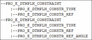
Image
The following table specifies the element tree constraints for this type.
Placement Constraint Element
Placement Constraint Member Elements
Valid Value
PRO_E_DTMPLN_CONSTRAINT (Constraint 1)
PRO_E_DTMPLN_CONSTR_TYPE
PRO_DTMPLN_THRU
PRO_E_DTMPLN_CONSTR_REF
PRO_AXIS, PRO_CURVE (STRAIGHT), PRO_EDGE (STRAIGHT)
PRO_E_DTMPLN_CONSTRAINT (Constraint 2)
PRO_E_DTMPLN_CONSTR_TYPE
PRO_DTMPLN_ANG
PRO_E_DTMPLN_CONSTR_REF
PRO_SURFACE (Plane),
PRO_E_DTMPLN_CONSTR_REF_ANGLE
Angle value (-360.0, 360.0)
Example 7: Through a Linear Reference (Axis, Inferred Axis, Straight Edge or Curve) and a Point
The element tree structure of a plane passing through an axis or an inferred axis and a point is shown in the following figure. An inferred axis is the axis of a surface of revolution like, Cylinder, Cone, Sphere, Torus or any other general surface of revolution.
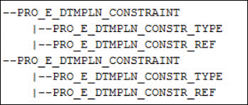
Image
The following table specifies the element tree constraints for this type.
Placement Constraint Element
Placement Constraint Member Elements
Valid Value
PRO_E_DTMPLN_CONSTRAINT (Constraint 1)
PRO_E_DTMPLN_CONSTR_TYPE
PRO_DTMPLN_THRU
PRO_E_DTMPLN_CONSTR_REF
PRO_AXIS, PRO_CURVE (STRAIGHT), PRO_EDGE (STRAIGHT, PRO_SURFACE(CYLINDER/CONE/SPHERE/TORUS/General surface of revolution)
PRO_E_DTMPLN_CONSTRAINT (Constraint 2)
PRO_E_DTMPLN_CONSTR_TYPE
PRO_DTMPLN_THRU
PRO_E_DTMPLN_CONSTR_REF
PRO_POINT, PRO_EDGE_START, PRO_EDGE_END, PRO_CRV_START, PRO_CRV_END
Example 8: Normal to a Linear Reference (Axis, Inferred Axis, Straight Edge or Curve) and a Point
The element tree structure of a plane normal to an axis or inferred axis and passing through a point is shown in the following figure.
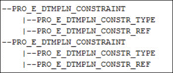
Image
The following table specifies the element tree constraints for this type.
Placement Constraint Element
Placement Constraint Member Elements
Valid Value
PRO_E_DTMPLN_CONSTRAINT (Constraint 1)
PRO_E_DTMPLN_CONSTR_TYPE
PRO_DTMPLN_NORM
PRO_E_DTMPLN_CONSTR_REF
PRO_AXIS, PRO_CURVE (STRAIGHT), PRO_EDGE (STRAIGHT), PRO_SURFACE(CYLINDER/CONE/SPHERE/TORUS/
General surface of revolution)
PRO_E_DTMPLN_CONSTRAINT (Constraint 2)
PRO_E_DTMPLN_CONSTR_TYPE
PRO_DTMPLN_THRU
PRO_E_DTMPLN_CONSTR_REF
PRO_POINT, PRO_EDGE_START, PRO_EDGE_END, PRO_CRV_START, PRO_CRV_END
Example 9: Midplane to a Plane and Parallel to Another Plane
The element tree structure of a midplane to a plane or a planar surface and parallel to another plane or planar surface, when these two references are parallel, is shown in the following figure.
Image
The following table specifies the element tree constraints for this type.
Placement Constraint Element
Placement Constraint Member Elements
Valid Value
PRO_E_DTMPLN_CONSTRAINT (Constraint 1)
PRO_E_DTMPLN_CONSTR_TYPE
PRO_DTMPLN_MIDPLN
PRO_E_DTMPLN_CONSTR_REF
PRO_SURFACE (Plane)
PRO_E_DTMPLN_CONSTRAINT (Constraint 2)
PRO_E_DTMPLN_CONSTR_TYPE
PRO_DTMPLN_PRL
PRO_E_DTMPLN_CONSTR_REF
PRO_SURFACE (Plane)
Example 10: Midplane to a Plane and at an Angle to Another Plane
The element tree structure of a midplane to a plane or a planar surface and angular to another plane or planar surface, when these two references are intersecting, is shown in the following figure.
Image
The following table specifies the element tree constraints for this type.
Placement Constraint Element
Placement Constraint Member Elements
Valid Value
PRO_E_DTMPLN_CONSTRAINT (Constraint 1)
PRO_E_DTMPLN_CONSTR_TYPE
PRO_DTMPLN_MIDPLN
PRO_E_DTMPLN_CONSTR_REF
PRO_SURFACE (Plane)
PRO_E_DTMPLN_CONSTRAINT (Constraint 2)
PRO_E_DTMPLN_CONSTR_TYPE
PRO_DTMPLN_BISECTOR1
PRO_DTMPLN_BISECTOR2
PRO_E_DTMPLN_CONSTR_REF
PRO_SURFACE (Plane)
Example 11: Midplane to a Plane and Midplane to a Point
The element tree structure of a midplane to a plane or a planar surface and midplane to a point, where the point does not lie on the plane, is shown in the following figure.
Image
The following table specifies the element tree constraints for this type.
Placement Constraint Element
Placement Constraint Member Elements
Valid Value
PRO_E_DTMPLN_CONSTRAINT (Constraint 1)
PRO_E_DTMPLN_CONSTR_TYPE
PRO_DTMPLN_MIDPLN
PRO_E_DTMPLN_CONSTR_REF
PRO_SURFACE (Plane)
PRO_E_DTMPLN_CONSTRAINT (Constraint 2)
PRO_E_DTMPLN_CONSTR_TYPE
PRO_DTMPLN_MIDPLN
PRO_E_DTMPLN_CONSTR_REF
PRO_POINT,
PRO_EDGE_START,
PRO_EDGE_END,
PRO_CRV_START,
PRO_CRV_END
Example 12: Through Three Points
The element tree structure of a plane passing through three non-collinear points is shown in the following figure.
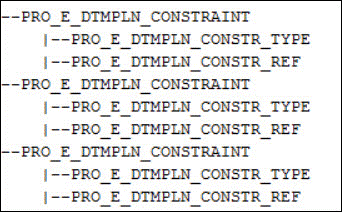
Image
The following table specifies the element tree constraints for this type.
Placement Constraint Element
Placement Constraint Member Elements
Valid Value
PRO_E_DTMPLN_CONSTRAINT (Constraint 1)
PRO_E_DTMPLN_CONSTR_TYPE
PRO_DTMPLN_THRU
PRO_E_DTMPLN_CONSTR_REF
PRO_POINT, PRO_EDGE_START,
PRO_EDGE_END,
PRO_CRV_START,PRO_CRV_END
PRO_E_DTMPLN_CONSTRAINT (Constraint 2)
PRO_E_DTMPLN_CONSTR_TYPE
PRO_DTMPLN_THRU
PRO_E_DTMPLN_CONSTR_REF
PRO_POINT, PRO_EDGE_START, PRO_EDGE_END, PRO_CRV_START, PRO_CRV_END
PRO_E_DTMPLN_CONSTRAINT (Constraint 3)
PRO_E_DTMPLN_CONSTR_TYPE
PRO_DTMPLN_THRU
PRO_E_DTMPLN_CONSTR_REF
PRO_POINT, PRO_EDGE_START, PRO_EDGE_END, PRO_CRV_START, PRO_CRV_END
Example 13: To Flip Direction
The datum plane normal that is the Z-direction can be flipped for any of the types. The following table specifies the element tree to flip the plane.
Element ID
Valid Value
PRO_E_DTMPLN_FLIP_DIR
PRO_DTMPLN_FLIP_DIR_NO or PRO_DTMPLN_FLIP_DIR_YES
Example 14: To Fit Outline to a Reference
The datum plane outline can be fit to a reference. The following figure shows the element tree structure using the fit elements.
Image
The following table specifies the element tree to use fit elements.
Fit Compound Element
Fit Member Elements
Valid Value
PRO_E_DTMPLN_FIT
PRO_E_DTMPLN_FIT _TYPE
PRO_DTMPLN_FIT_PART
PRO_E_DTMPLN_FIT _REF
PRO_PART
Datum Point Features
The element tree for a datum point feature is documented in the header file ProDtmPnt.h. Apart from the usual elements for the tree root and feature type, a datum point contains the datum point type. The types of datum points available are:
Sketched Datum Point
A sketched datum point is created by sketching the point in the sketcher mode after specifying the plane on which the user wants to create a point.
Note
The sketched datum point is obsolete. Hence, the element tree for sketched datum point defined in the header file ProDtmPnt.h is no longer supported. The sketched datum points are consolidated within the sketched feature as a geometry point. The geometry entities within the sketched feature generate the corresponding datum entities. To create new sketched datum points, you must use the element tree for sketched datum curves defined in the header file ProDtmCrv.h. Refer to the section Sketched Datum Curves, for more information on sketched datum curves.
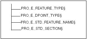
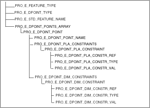
The following figure shows the element tree for a sketched datum point.
Image
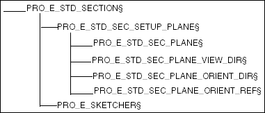
Define the following sub elements of PRO_E_STD_SECTION to complete the sketched datum point feature.
Image
See the section Element Trees: Sketched Features for techniques that must be used to create a sketched feature, like a sketched datum point.
Feature Elements
The following table describes the elements of the element tree for sketched datum points:
Element ID
Element Name
Data Type
Valid Value
PRO_E_FEATURE_TYPE
Feature Type
PRO_VALUE_TYPE_INT
PRO_FEAT_DATUM_POINT
PRO_E_DPOINT_TYPE
Datum Point Type
PRO_VALUE_TYPE_INT
PRO_DPOINT_TYPE
_SKETCHED
PRO_E_STD_FEATURE_NAME
Feature Name
PRO_VALUE_TYPE
_WSTRING
PRO_E_STD_SECTION
Section
Compound
See ProStdSection.h
Example 2: Creating a Sketched Datum Point
The sample code in the file UgSketchedPointCreate.c located at <creo_toolkit_loadpoint>/protk_appls/pt_userguide/ptu_featcreat shows how to create a Sketched Datum Point. The user is prompted to select the sketching planes, orientation planes, and then the reference edges for the sketch. The user is also required to enter the X and Y offsets to be applied to the sketch from the projected edges.
Field Datum Point
A field datum point is created by selecting any point on a surface, edge, curve, or quilt. The point is located depending on the UV parameters. The location of the field point depends on the UV values of the point on the surface, edge, curve, or quilt.
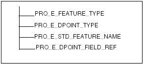
The following figure shows the element tree for the field datum point.
Image
Feature Elements
The following table describes the elements of the element tree for the field datum points:
Element ID
Element Name
Data Type
Valid Value
PRO_E_FEATURE_TYPE
Feature Type
PRO_VALUE_TYPE_INT
PRO_FEAT_DATUM_POINT
PRO_E_DPOINT_TYPE
Datum Point Type
PRO_VALUE_TYPE_INT
PRO_DPOINT_
TYPE_FIELD
PRO_E_STD_FEATURE_NAME
Feature Name
PRO_VALUE_TYPE_
WSTRING
PRO_E_DPOINT_
FIELD_REF
Placement reference
PRO_VALUE_TYPE_SELECTION
Surface, Edge, Curve, or Quilt. Note: UV is used to specify exact location.
Example 3: Creating a Field Datum Point
The sample code in the file UgFieldPointCreate.c located at <creo_toolkit_loadpoint>/protk_appls/pt_userguide/ptu_featcreat shows how to create a Field Datum Point on an edge or surface. The user is prompted to select a point on a curve or a surface.
Offset Csys Datum Point
An Offset Csys Datum point is created using the coordinate system and values along the coordinate axes. Three types of coordinate systems can be used:
•  Cartesian—Requires values along X, Y, Z axis.
•  Cylindrical—Requires values along R, theta, Z axis.
•  Spherical—Requires values along r,phi theta axis.
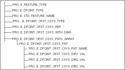
The following figure shows the element tree for Offset Csys Datum Point.
Image
Feature Elements
The following table describes the elements in the element tree for datum points.
Element ID
Element Name
Data Type
Valid Value
PRO_E_FEATURE_TYPE
Feature Type
PRO_VALUE_TYPE_INT
PRO_FEAT_DATUM_POINT
PRO_E_DPOINT_TYPE
Datum Point Type
PRO_VALUE_TYPE_INT
PRO_DPOINT_TYPE_
OFFSET_CSYS
PRO_E_STD_FEATURE_NAME
Feature Name
PRO_VALUE_TYPE_
WSTRING
PRO_E_DPOINT_OFST
_CSYS_TYPE
Reference Csys Type
PRO_VALUE_TYPE_INT
See ProDtmpntOffCsysType
PRO_E_DPOINT_OFST
_CSYS_REF
Reference Csys
PRO_VALUE_TYPE_SELECTION
Csys
PRO_E_DPOINT_OFST
_CSYS_WITH_DIMS
Parametric or Explicit with or without dimensions
PRO_VALUE_TYPE_INT
PRO_B_TRUE or PRO_B_FALSE
PRO_E_DPOINT_OFST
_CSYS_PNTS_ARRAY
Array of Points List
PRO_E_DPOINT_OFST
_CSYS_PNT
One Point
Compound
PRO_E_DPOINT_OFST
_CSYS_PNT_NAME
Point Name
PRO_VALUE_TYPE_
WSTRING
PRO_E_DPOINT_OFST
_CSYS_DIR1_VAL
X, R, or pi
PRO_VALUE_TYPE
_DOUBLE
Depends on PRO_E_DPOINT_OFST
_CSYS_TYPE
PRO_E_DPOINT_OFST
_CSYS_DIR2_VAL
Y, theta, or phi
PRO_VALUE_TYPE
_DOUBLE
Depends on PRO_E_DPOINT_OFST
_CSYS_TYPE
PRO_E_DPOINT_OFST
_CSYS_DIR3_VAL
Z, Z, or theta
PRO_VALUE_TYPE
_DOUBLE
Depends on PRO_E_DPOINT_OFST
_CSYS_TYPE
Example 4: Creating an Offset Csys Datum Point
The sample code in the file UgOffsetPointCreate.c located at <creo_toolkit_loadpoint>/protk_appls/pt_userguide/ptu_featcreat shows how to create an Offset Datum Point at an offset from a specified coordinate system. The user is prompted to select the coordinate system.
General Datum Point
A general datum point is created and constrained based on the selection context. The supported types are:
•  Point on vertex
•  Offset point
•  Project point
•  Point at intersection of three surfaces
•  On or Offset surface
•  Point at intersection of curve and surface
•  Center of curve or surface
•  Point at intersection of two curves
•  Point on curve
When there are multiple intersections, the point location of general datum point depends on the following:
•  Point at intersection of edge and edge—t value of point on second edge
•  Point at intersection of edge and plane—t value of point on edge
•  Point at intersection of curve and plane—t value of point on curve
•  Point at intersection of two curves—t value of point on second curve
•  Point at intersection of curve and surface—t value of point on curve
•  Point at intersection of curve and axis—t value of point on curve
The following figure shows the element tree of a general datum point.
Image
Feature Elements
The following table describes the elements of the element tree for datum points.
Element ID
Element Name
Data Type
Valid Value
PRO_E_FEATURE_TYPE
Feature Type
PRO_VALUE_TYPE_INT
PRO_FEAT_DATUM_POINT
PRO_E_DPOINT_TYPE
Datum Point Type
PRO_VALUE_TYPE_INT
PRO_DPOINT_TYPE
_GENERAL
PRO_E_STD_FEATURE_NAME
Feature Name
PRO_VALUE_TYPE
_WSTRING
PRO_E_DPOINT_POINTS
_ARRAY
Points List
Array
Not applicable
PRO_E_DPOINT_POINT
One Point
Compound
Not applicable
PRO_E_DPOINT
_POINT_NAME
Point Name
PRO_VALUE_TYPE
_WSTRING
PRO_E_DPOINT_PLA
_CONSTRAINTS
Placement Constraints
Array
Not applicable
PRO_E_DPOINT_PLA
_CONSTRAINT
One Placement Constraint
Compound
Not applicable
PRO_E_DPOINT_PLA
_CONSTR_REF
Placement Reference
PRO_VALUE_TYPE_SELECTION
Depends on the context. See PRO_E_DPOINT_PLA
_CONSTR_REF
.
PRO_E_DPOINT_PLA
_CONSTR_TYPE
Constraint Type
PRO_VALUE_TYPE_INT
See ProDtmpntConstrType.
PRO_E_DPOINT_PLA
_CONSTR_VAL
Value
PRO_VALUE_TYPE
_DOUBLE
PRO_E_DPOINT_DIM
_CONSTRAINTS
Dimension Constraints
Array
Not applicable
PRO_E_DPOINT_DIM
_CONSTRAINT
One Dimension Constraint
Compound
Not applicable
PRO_E_DPOINT_DIM
_CONSTR_REF
Dimension Reference
PRO_VALUE_TYPE_SELECTION
PRO_E_DPOINT_DIM
_CONSTR_TYPE
Constraint Type
PRO_VALUE_TYPE_
INT
Depends on the context. See Constraint Type.
PRO_E_DPOINT_DIM
_CONSTR_VAL
Value
PRO_VALUE_TYPE_
DOUBLE
See ProDtmpntConstrType
Placement Constraint References
Valid values for the PRO_E_DPOINT_PLA_CONSTR_REF placement reference are as follows:
•  Curve—SEL_3D_CURVE, SEL_3D_CABLE, SEL_IGES_WF
•  Edge—SEL_3D_EDG
•  Axis—SEL_3D_AXIS
•  Vertex—SEL_3D_VERT or SEL_CURVE_END
•  CSYS—SEL_3D_CSYS
•  Surface—SEL_3D_SRF, SEL_3D_SRF_LIST
•  Datum Pnt—SEL_3D_PNT
Placement Constraint Type
Valid values for PRO_E_DPOINT_PLA_CONSTR_TYPE are as follows:
•  PRO_DTMPNT_CONSTR_TYPE_ON
•  PRO_DTMPNT_CONSTR_TYPE_OFFSET
•  PRO_DTMPNT_CONSTR_TYPE_CENTER
•  PRO_DTMPNT_CONSTR_TYPE_PARALLEL
•  PRO_DTMPNT_CONSTR_TYPE_NORMAL
•  PRO_DTMPNT_CONSTR_TYPE_PROJECT
•  PRO_DTMPNT_CONSTR_TYPE_CARTESIAN
•  PRO_DTMPNT_CONSTR_TYPE_CYLINDRICAL
•  PRO_DTMPNT_CONSTR_TYPE_SPHERICAL
The last three are used when defining a point offset to a coordinate system.
Constraint References
Valid values for the PRO_E_DPOINT_DIM_CONSTR_REF dimension references are as following:
•  Curve—SEL_3D_CURVE, SEL_3D_CABLE, SEL_CRV_PNT, SEL_IGES_WF
•  Edge—SEL_3D_EDG, SEL_EDG_PNT
•  Axis—SEL_3D_AXIS
•  Coordinate system—SEL_3D_CSYS
•  Vertex—SEL_3D_VERT or SEL_CURVE_END
•  Surface—SEL_3D_SRF, SEL_SRF_PNT, SEL_3D_SRF_LIST
•  Coordinate system axis—SEL_3D_CSYS_AXIS
•  Datum Point—SEL_3D_PNT
Constraint Type
Valid values for PRO_E_DPOINT_DIM_CONSTR_TYPE are as follows:
•  PRO_DTMPNT_CONSTR_TYPE_OFFSET
•  PRO_DTMPNT_CONSTR_TYPE_LENGTH
•  PRO_DTMPNT_CONSTR_TYPE_RATIO
•  PRO_DTMPNT_CONSTR_TYPE_LENGTH_END
•  PRO_DTMPNT_CONSTR_TYPE_RATIO
•  PRO_DTMPNT_CONSTR_TYPE_RATIO_END
•  PRO_DTMPNT_CONSTR_TYPE_ALONG_X
•  PRO_DTMPNT_CONSTR_TYPE_ALONG_Y
•  PRO_DTMPNT_CONSTR_TYPE_ALONG_Z
Example 5: Creating General Datum Point
The sample code in the file UgGeneralPointCreate.c located at <creo_toolkit_loadpoint>/protk_appls/pt_userguide/ptu_featcreat shows how to create a General Datum Point formed at the intersection of three selected surfaces. The user is prompted to select the three surfaces.
Examples
Example 1: Point on a Vertex
To create a datum point on the vertex, the following constraints are required.
Placement Constraint Element
Reference Element
Valid Value
PRO_E_DPOINT_PLA_CONSTRAINT (Constraint 1)
PRO_E_DPOINT_PLA_CONSTR_REF
Vertex
PRO_E_DPOINT_PLA_CONSTR_TYPE
PRO_DTMPNT_CONSTR_TYPE_ON
PRO_E_DPOINT_PLA_CONSTR_VAL
Not applicable
Example 2: Offset Point
To create one or more datum points at an offset, the following constraints are required.
Placement Constraint Element
Reference Element
Valid Value
PRO_E_DPOINT_PLA_CONSTRAINT (Constraint 1)
PRO_E_DPOINT_PLA_CONSTR_REF
Vertex, Csys, or DPnt
PRO_E_DPOINT_PLA_CONSTR_TYPE
PRO_DTMPNT_CONSTR_TYPE_OFFSET
PRO_E_DPOINT_PLA_CONSTR_VAL
Offset value.
The following tables provide valid values for Constraint 2. You can create a point at an offset using values from one of the following tables for Constraint 2.
Placement Constraint Element
Reference Element
Valid Value
PRO_E_DPOINT_PLA_CONSTRAINT (Constraint 2)
PRO_E_DPOINT_PLA_CONSTR_REF
Curve, Edge or Axis
PRO_E_DPOINT_PLA_CONSTR_TYPE
PRO_DTMPNT_CONSTR_TYPE_PARALLEL
PRO_E_DPOINT_PLA_CONSTR_VAL
Not applicable
OR
Placement Constraint Element
Reference Element
Valid Value
PRO_E_DPOINT_PLA_CONSTRAINT (Constraint 2)
PRO_E_DPOINT_PLA_CONSTR_REF
Surface
PRO_E_DPOINT_PLA_CONSTR_TYPE
PRO_DTMPNT_CONSTR_TYPE_NORMAL
PRO_E_DPOINT_PLA_CONSTR_VAL
Not applicable
OR
Placement Constraint Element
Reference Element
Valid Value
PRO_E_DPOINT_PLA_CONSTRAINT (Constraint 2)
PRO_E_DPOINT_PLA_CONSTR_REF
Csys Axis
PRO_E_DPOINT_PLA_CONSTR_TYPE
PRO_DTMPNT_CONSTR_TYPE_PARALLEL
PRO_E_DPOINT_PLA_CONSTR_VAL
Not applicable
OR
Placement Constraint Element
Reference Element
Valid Value
PRO_E_DPOINT_PLA_CONSTRAINT (Constraint 2)
PRO_E_DPOINT_PLA_CONSTR_REF
Csys
PRO_E_DPOINT_PLA_CONSTR_TYPE
PRO_DTMPNT_CONSTR_TYPE_CARTESIAN or
PRO_DTMPNT_CONSTR_TYPE_CYLINDRICAL or PRO_DTMPNT_CONSTR_TYPE_SPHERICAL
PRO_E_DPOINT_PLA_CONSTR_VAL
Not applicable
The following table provides valid values for dimension constraints.
Dimension Constraint Element
Reference Element
Valid Value
PRO_E_DPOINT_DIM_CONSTRAINT (Constraint 3)
PRO_E_DPOINT_DIM_CONSTR_REF
Not applicable
PRO_E_DPOINT_DIM_CONSTR_TYPE
PRO_DTMPNT_CONSTR_TYPE_ALONG_X
PRO_E_DPOINT_DIM_CONSTR_VAL
Offset Value
PRO_E_DPOINT_DIM_CONSTRAINT (Constraint 4)
PRO_E_DPOINT_DIM_CONSTR_REF
Not applicable
PRO_E_DPOINT_DIM_CONSTR_TYPE
PRO_DTMPNT_CONSTR_TYPE_ALONG_Y
PRO_E_DPOINT_DIM_CONSTR_VAL
Offset Value
PRO_E_DPOINT_DIM_CONSTRAINT (Constraint 5)
PRO_E_DPOINT_DIM_CONSTR_REF
Not applicable
PRO_E_DPOINT_DIM_CONSTR_TYPE
PRO_DTMPNT_CONSTR_TYPE_ALONG_Z
PRO_E_DPOINT_DIM_CONSTR_VAL
Offset Value
As per Offset types the values are as follows:
 
CARTESIAN
CYLINDRICAL
SPHERICAL
PRO_DTMPNT_CONSTR_TYPE_ALONG_X
X
R
RHO
PRO_DTMPNT_CONSTR_TYPE_ALONG_Y
Y
THETA
PHI
PRO_DTMPNT_CONSTR_TYPE_ALONG_Z
Z
Z
THETA
Example 3: Point at Intersection of Three Surfaces
To create a datum point at the intersection of three surfaces, use the following constraints. Each surface can be a part surface, surface feature, or datum plane.
Placement Constraint Element
Reference Element
Valid Value
PRO_E_DPOINT_PLA_CONSTRAINT (Constraint 1)
PRO_E_DPOINT_PLA_CONSTR_REF
Surface
PRO_E_DPOINT_PLA_CONSTR_TYPE
PRO_DTMPNT_CONSTR_TYPE_ON
PRO_E_DPOINT_PLA_CONSTR_VAL
Not applicable
PRO_E_DPOINT_PLA_CONSTRAINT (Constraint 2)
PRO_E_DPOINT_PLA_CONSTR_REF
Surface
PRO_E_DPOINT_PLA_CONSTR_TYPE
PRO_DTMPNT_CONSTR_TYPE_ON
PRO_E_DPOINT_PLA_CONSTR_VAL
Not applicable
PRO_E_DPOINT_PLA_CONSTRAINT (Constraint 3)
PRO_E_DPOINT_PLA_CONSTR_REF
Surface
PRO_E_DPOINT_PLA_CONSTR_TYPE
PRO_DTMPNT_CONSTR_TYPE_ON
PRO_E_DPOINT_PLA_CONSTR_VAL
Not applicable
Example 4: Point On a Surface or Offset from a Surface
The following constraints are required to create a point on a surface or at an offset distance from a surface:
Placement Constraint Element
Reference Element
Valid Value
PRO_E_DPOINT_PLA_CONSTRAINT (Constraint 1)
PRO_E_DPOINT_PLA_CONSTR_REF
Surface
PRO_E_DPOINT_PLA_CONSTR_TYPE
PRO_DTMPNT_CONSTR_TYPE_ON or PRO_DTMPNT_CONSTR_TYPE_OFFSET
PRO_E_DPOINT_PLA_CONSTR_VAL
Not applicable
PRO_E_DPOINT_PLA_CONSTRAINT (Constraint 2)
PRO_E_DPOINT_PLA_CONSTR_REF
Edge or Surface
PRO_E_DPOINT_PLA_CONSTR_TYPE
PRO_DTMPNT_CONSTR_TYPE_OFFSET
PRO_E_DPOINT_PLA_CONSTR_VAL
Offset value
PRO_E_DPOINT_PLA_CONSTRAINT (Constraint 3)
PRO_E_DPOINT_PLA_CONSTR_REF
Edge or Surface
PRO_E_DPOINT_PLA_CONSTR_TYPE
PRO_DTMPNT_CONSTR_TYPE_OFFSET
PRO_E_DPOINT_PLA_CONSTR_VAL
Offset value
Example 5: Point at Intersection of a Curve and a Surface
To create a datum point at the intersection of a curve and a surface, use the following constraints. The curve can be a part edge, surface feature edge, datum curve, axis, or an imported datum curve. The surface can be a part surface, surface feature, or datum plane.
Placement Constraint Element
Reference Element
Valid Value
PRO_E_DPOINT_PLA_CONSTRAINT (Constraint 1)
PRO_E_DPOINT_PLA_CONSTR_REF
Curve, axis, edge, or
surface
PRO_E_DPOINT_PLA_CONSTR_TYPE
PRO_DTMPNT_CONSTR_TYPE_ON
PRO_E_DPOINT_PLA_CONSTR_VAL
Not applicable
PRO_E_DPOINT_PLA_CONSTRAINT (Constraint 2)
PRO_E_DPOINT_PLA_CONSTR_REF
- If value of constraint 1 is Curve, Axis, or Edge, the value of constraint 2 is surface.
- If value of constraint 1 is surface, the value of constraint 2 is Curve, Axis, or Edge.
PRO_E_DPOINT_PLA_CONSTR_TYPE
PRO_DTMPNT_CONSTR_TYPE_ON
PRO_E_DPOINT_PLA_CONSTR_VAL
Not applicable
Note
If more than one intersections exist, the point is created at the intersection nearest to the curve reference parameter value.
Example 6: Point At Center of Curve or Surface
To create a datum point at the center of an arc or circle entity, use the following constraints.
Placement Constraint Element
Reference Element
Valid Value
PRO_E_DPOINT_PLA_CONSTRAINT (Constraint 1)
PRO_E_DPOINT_PLA_CONSTR_REF
Curve, edge, or surface (Sphere)
PRO_E_DPOINT_PLA_CONSTR_TYPE
PRO_DTMPNT_CONSTR_TYPE_CENTER
PRO_E_DPOINT_PLA_CONSTR_VAL
Not applicable
Example 7: Point at Intersection of Two Curves
To create a point at intersection of two curves, use the following constraints.
Placement Constraint Element
Reference Element
Valid Value
PRO_E_DPOINT_PLA_CONSTRAINT (Constraint 1)
PRO_E_DPOINT_PLA_CONSTR_REF
Curve, edge, or axis
PRO_E_DPOINT_PLA_CONSTR_TYPE
PRO_DTMPNT_CONSTR_TYPE_ON
PRO_E_DPOINT_PLA_CONSTR_VAL
Not applicable
PRO_E_DPOINT_PLA_CONSTRAINT (Constraint 2)
PRO_E_DPOINT_PLA_CONSTR_REF
Curve, edge, or axis
PRO_E_DPOINT_PLA_CONSTR_TYPE
PRO_DTMPNT_CONSTR_TYPE_ON
PRO_E_DPOINT_PLA_CONSTR_VAL
Not applicable
Note
If more than one intersections exist, the point is created at the intersection nearest to the second reference parameter value.
Example 8: Point On Curve
To create a datum point on a curve, the following constraints are required.
Placement Constraint Element
Reference Element
Valid Value
PRO_E_DPOINT_PLA_CONSTRAINT (Constraint 1)
PRO_E_DPOINT_PLA_CONSTR_REF
Curve, edge, or axis (It is valid with offset plane)
PRO_E_DPOINT_PLA_CONSTR_TYPE
PRO_DTMPNT_CONSTR_TYPE_ON
PRO_E_DPOINT_PLA_CONSTR_VAL
Not applicable
The following tables provide valid values for constraint 2. You can create a point on curve using values from one of the following tables for constraint 2.
Use the following values for constraint 2 if the length of curve from the start point or the end point is used to locate the point.
Placement Constraint Element
Reference Element
Valid Value
PRO_E_DPOINT_DIM_CONSTRAINT (Constraint 2)
PRO_E_DPOINT_DIM_CONSTR_REF
Curve (Use the same curve as used in Constraint 1)
PRO_E_DPOINT_DIM_CONSTR_TYPE
PRO_DTMPNT_CONSTR_TYPE_LENGTH or PRO_DTMPNT_CONSTR_TYPE_LENGTH_END
PRO_E_DPOINT_DIM_CONSTR_VAL
Length value (from curve start point or end point)
Use the following values for constraint 2 if the ratio of distance from the start point or the end point is used to locate the point.
Placement Constraint Element
Reference Element
Valid Value
PRO_E_DPOINT_DIM_CONSTRAINT (Constraint 2)
PRO_E_DPOINT_DIM_CONSTR_REF
Curve (Use the same curve as used in contrarian 1)
PRO_E_DPOINT_DIM_CONSTR_TYPE
PRO_DTMPNT_CONSTR_TYPE_RATIO or PRO_DTMPNT_CONSTR_TYPE_RATIO_END
PRO_E_DPOINT_DIM_CONSTR_VAL
Ratio value (from curve start or end)
Use the following values for constraint 2 if the offset surface is used to locate the point on curve.
Placement Constraint Element
Reference Element
Valid Value
PRO_E_DPOINT_DIM_CONSTRAINT (Constraint 2)
PRO_E_DPOINT_DIM_CONSTR_REF
Surface
PRO_E_DPOINT_DIM_CONSTR_TYPE
PRO_DTMPNT_CONSTR_TYPE_OFFSET
PRO_E_DPOINT_DIM_CONSTR_VAL
Offset value
Example 9: Project Datum Point On a Planar surface, Datum Plane, Datum Axis, Linear Curve or Linear Edge
To project a datum point on a planar surface, datum plane, or datum axis, the following constraints are required.
Placement Constraint Element
Reference Element
Valid Value
PRO_E_DPOINT_PLA_CONSTRAINT (Constraint 1)
PRO_E_DPOINT_PLA_CONSTR_REF
Datum point, end of curve, or vertex
PRO_E_DPOINT_PLA_CONSTR_TYPE
PRO_DTMPNT_CONSTR_TYPE_PROJECT
PRO_E_DPOINT_PLA_CONSTR_VAL
Not applicable
PRO_E_DPOINT_PLA_CONSTRAINT (Constraint 2)
PRO_E_DPOINT_PLA_CONSTR_REF
Axis, curve, or edge
PRO_E_DPOINT_PLA_CONSTR_TYPE
PRO_DTMPNT_CONSTR_TYPE_ON
PRO_E_DPOINT_PLA_CONSTR_VAL
Not applicable
OR
Placement Constraint Element
Reference Element
Valid Value
PRO_E_DPOINT_PLA_CONSTRAINT (Constraint 2)
PRO_E_DPOINT_PLA_CONSTR_REF
Surface
PRO_E_DPOINT_PLA_CONSTR_TYPE
PRO_DTMPNT_CONSTR_TYPE_ON
PRO_E_DPOINT_PLA_CONSTR_VAL
Not applicable
Datum Axis Features
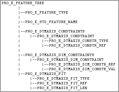
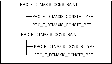
The basic element tree for creating axes is available in the include file ProDtmAxis.h. The following figure shows the basic structure of the element tree.
Image
Creo TOOLKIT supports creation of the following types of datum axes:
There is no single element that indicates the type in constraints element tree. The type is determined implicitly based on the constraint type and references. The types of the datum axis constraints for the references are defined by the enumerated type ProDtmaxisConstrType and are as follows:
•  PRO_DTMAXIS_CONSTR_TYPE_NORMAL— Positions the datum axis normal to the selected reference.
•  PRO_DTMAXIS_CONSTR_TYPE_THRU— Positions the datum axis through the selected reference.
•  PRO_DTMAXIS_CONSTR_TYPE_TANGENT— Positions the datum axis tangent to the selected reference.
•  PRO_DTMAXIS_CONSTR_TYPE_CENTER— Positions the datum axis through the center of the selected planar circular edge or curve and normal to the plane on which the selected curve or edge lies.
•  PRO_DTMAXIS_CONSTR_TYPE_PARALLEL— Positions the datum axis parallel to the selected reference.
Example 6: Creating a Datum Axis
The sample code in the file UgDatumAxisCreate.c located at <creo_toolkit_loadpoint>/protk_appls/pt_userguide/ptu_featcreat shows how to create a datum axis at the intersection of two selected surfaces. The user is prompted to select the two surfaces.
Examples
Example 1: Point on Surface
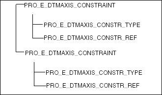
The element tree structure of the axis, created with type as PRO_DTMAXIS_PNT_SURF, is shown in the following figure.
Image
The following table specifies the constraints for the PRO_E_DTMAXIS_CONSTRAINT elements in the element tree for the point on surface type of axis.
Placement Constraint Element
Placement Constraint Member Elements
Valid Value
PRO_E_DTMAXIS_CONSTRAINT (Constraint 1)
PRO_E_DTMAXIS_CONSTR_TYPE
PRO_DTMAXIS_CONSTR_TYPE_THRU
PRO_E_DTMAXIS_CONSTR_REF
PRO_POINT
PRO_E_DTMAXIS_CONSTRAINT (Constraint 2)
PRO_E_DTMAXIS_CONSTR_TYPE
PRO_DTMAXIS_CONSTR_TYPE_NORMAL
PRO_E_DTMAXIS_CONSTR_REF
PRO_SURFACE
Example 2: Tangent
The element tree structure of the axis, created with type as Tangent, is shown in the following figure.
Image
The following table specifies the constraints for the PRO_E_DTMAXIS_CONSTRAINT elements in the element tree for the tangent type of axis.
Placement Constraint Element
Placement Constraint Member Elements
Valid Value
PRO_E_DTMAXIS_CONSTRAINT (Constraint 1)
PRO_E_DTMAXIS_CONSTR_TYPE
PRO_DTMAXIS_CONSTR_TYPE_TANGENT
PRO_E_DTMAXIS_CONSTR_REF
PRO_EDGE, PRO_CURVE
PRO_E_DTMAXIS_CONSTRAINT (Constraint 2)
PRO_E_DTMAXIS_CONSTR_TYPE
PRO_DTMAXIS_CONSTR_TYPE_THRU
PRO_E_DTMAXIS_CONSTR_REF
PRO_POINT, PRO_EDGE_START, PRO_EDGE_END,PRO_CRV_
START
, PRO_CRV_END
Example 3: Normal to a Linear Reference (Axis, Inferred Axis, Straight Edge or Curve)
The element tree structure of the axis, created with type as Normal, is shown in the following figure.
Image
The following table specifies the constraints for the PRO_E_DTMAXIS_CONSTRAINT elements in the element tree for the Normal type of axis.
Placement Constraint Element
Placement Constraint Member Elements
Valid Value
PRO_E_DTMAXIS_CONSTRAINT (Constraint 1)
PRO_E_DTMAXIS_CONSTR_TYPE
PRO_DTMAXIS_CONSTR_TYPE_THRU
PRO_E_DTMAXIS_CONSTR_REF
PRO_POINT, PRO_EDGE_START, PRO_EDGE_END, PRO_CRV_START, PRO_CRV_END
PRO_E_DTMAXIS_CONSTRAINT (Constraint 2)
PRO_E_DTMAXIS_CONSTR_TYPE
PRO_E_DTMAXIS_CONSTR_REF
PRO_EDGE (STRAIGHT), PRO_CURVE (STRAIGHT), PRO_AXIS, PRO_SURFACE (CYLINDER/CONE/SPHERE/TORUS/
General surface of revolution)
. The inferred axis will be used as the reference.
Note
For the Normal type of datum axis creation, the reference provided for the first constraint that is, PRO_DTMAXIS_CONSTR_TYPE_THRU should not lie on the reference provided for second constraint that is PRO_DTMAXIS_CONSTR_TYPE_NORMAL.
Example 4: Parallel to a Linear Reference (Axis, Inferred Axis, Straight Edge or Curve)
The element tree structure of the axis, created with type as Parallel, is shown in the following figure.
Image
The following table specifies the constraints for the PRO_E_DTMAXIS_CONSTRAINT elements in the element tree for the Parallel type of axis.
Placement Constraint Element
Placement Constraint Member Elements
Valid Value
PRO_E_DTMAXIS_CONSTRAINT (Constraint 1)
PRO_E_DTMAXIS_CONSTR_TYPE
PRO_DTMAXIS_CONSTR_TYPE_THRU
PRO_E_DTMAXIS_CONSTR_REF
PRO_POINT, PRO_EDGE_START, PRO_EDGE_END,PRO_CRV_START, PRO_CRV_END
PRO_E_DTMAXIS_CONSTRAINT (Constraint 2)
PRO_E_DTMAXIS_CONSTR_TYPE
PRO_DTMAXIS_CONSTR_TYPE_PARALLEL
PRO_E_DTMAXIS_CONSTR_REF
PRO_EDGE (STRAIGHT), PRO_CURVE (STRAIGHT), PRO_AXIS, PRO_SURFACE (CYLINDER/CONE/SPHERE/TORUS/
General surface of revolution)
. The inferred axis will be used as reference.
Example 5: Through Edge or Surface
The element tree structure of the axis, created with type Through an Edge or a Surface, is shown in the following figure.
Image
The following table specifies the constraints for the PRO_E_DTMAXIS_CONSTRAINT elements in the element tree for the through type of axis.
Placement Constraint Element
Placement Constraint Member Elements
Valid Value
PRO_E_DTMAXIS_CONSTRAINT (Constraint 1)
PRO_E_DTMAXIS_CONSTR_TYPE
PRO_DTMAXIS_CONSTR_TYPE_THRU
PRO_E_DTMAXIS_CONSTR_REF
PRO_EDGE (Straight), PRO_SURFACE (Cylinder)
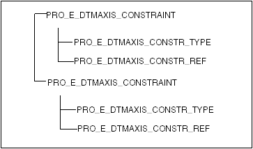
Example 6: Two Planes
The element tree structure of the axis, created using the type as two planes, is as shown in the following figure.
Image
The following table specifies the constraints for the PRO_E_DTMAXIS_CONSTRAINT elements in the element tree for the two planes reference scheme.
Placement Constraint Element
Placement Constraint Member Elements
Valid Value
PRO_E_DTMAXIS_CONSTRAINT (Constraint 1)
PRO_E_DTMAXIS_CONSTR_TYPE
PRO_DTMAXIS_CONSTR_TYPE_THRU
PRO_E_DTMAXIS_CONSTR_REF
PRO_SURFACE (Planar)
PRO_E_DTMAXIS_CONSTRAINT (Constraint 2)
PRO_E_DTMAXIS_CONSTR_TYPE
PRO_DTMAXIS_CONSTR_TYPE_THRU
PRO_E_DTMAXIS_CONSTR_REF
PRO_SURFACE (Planar)
Example 7: Two Points
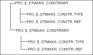
The element tree structure of the axis, created using the type as two points, is shown in the following figure.
Image
The following table specifies the constraints for the PRO_E_DTMAXIS_CONSTRAINT elements in the element tree for the two points type of axis.
Placement Constraint Element
Placement Constraint Member Elements
Valid Value
PRO_E_DTMAXIS_CONSTRAINT (Constraint 1)
PRO_E_DTMAXIS_CONSTR_TYPE
PRO_DTMAXIS_CONSTR_TYPE_THRU
PRO_E_DTMAXIS_CONSTR_REF
PRO_POINT, PRO_EDGE_START, PRO_EDGE_END, PRO_CRV_START, PRO_CRV_END
PRO_E_DTMAXIS_CONSTRAINT (Constraint 2)
PRO_E_DTMAXIS_CONSTR_TYPE
PRO_DTMAXIS_CONSTR_TYPE_THRU
PRO_E_DTMAXIS_CONSTR_REF
PRO_POINT, PRO_EDGE_START, PRO_EDGE_END, PRO_CRV_START, PRO_CRV_END
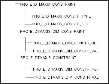
Example 8: Normal Planes
The element tree structure of the axis, created using the type as Normal Planes, is shown in the following figure.
Image
The following table specifies the constraints for the PRO_E_DTMAXIS_CONSTRAINT elements in the element tree for the normal plane type of axis.
Placement Constraint Element
Placement Constraint Member Elements
Valid Value
PRO_E_DTMAXIS_CONSTRAINT (Constraint 1)
PRO_E_DTMAXIS_CONSTR_TYPE
PRO_DTMAXIS_CONSTR_TYPE_NORMAL
PRO_E_DTMAXIS_CONSTR_REF
PRO_SURFACE (Planar)
PRO_E_DTMAXIS_DIM_CONSTRAINT (Constraint 2)
PRO_E_DTMAXIS_DIM_CONSTR_REF
PRO_SURFACE (Planar), PRO_AXIS, PRO_EDGE
PRO_E_DTMAXIS_DIM_CONSTR_VAL
Valid dimension
PRO_E_DTMAXIS_DIM_CONSTRAINT (Constraint 3)
PRO_E_DTMAXIS_DIM_CONSTR_REF
PRO_SURFACE (Planar), PRO_AXIS, PRO_EDGE
PRO_E_DTMAXIS_DIM_CONSTR_VAL
Valid dimension
Datum Coordinate System Features
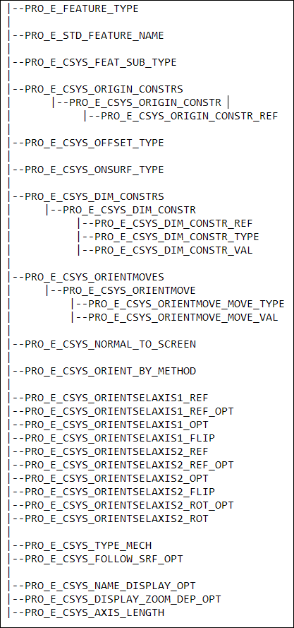
The following figure illustrates the general structure of the element tree for coordinate system features.
Image
Feature Elements
The following table describes the elements in the element tree for coordinate system feature.
Element Id
Element Name
Data Type
Valid Values
PRO_E_FEATURE_TYPE
Feature Type
PRO_VALUE_TYPE_INT
PRO_FEAT_CSYS
PRO_E_STD_FEATURE_NAME
Feature Name
PRO_VALUE_TYPE
_WSTRING
 
PRO_E_CSYS_FEAT_SUB_TYPE
Feature Sub Type
Specifies if the feature subtype is a coordinate system. The valid value is defined in the enumerated data type ProCsysFeatSubType:
•  PRO_CSYS_SUB_TYPE_ROSETTE—This is the default value. Specifies that the coordinate system is of the type rosette.
PRO_VALUE_TYPE_INT
ProCsysFeatSubType
PRO_E_CSYS_ORIGIN_CONSTRS
Origin Constraints
Array
 
PRO_E_CSYS_ORIGIN_CONSTR
Origin Constraint
Compound
 
PRO_E_CSYS_ORIGIN_CONSTR_REF
Origin Reference
PRO_VALUE_TYPE_SELECTION
 
PRO_E_CSYS_OFFSET_TYPE
Origin Offset Type
PRO_VALUE_TYPE_INT
ProCsysOffsetType
PRO_E_CSYS_ONSURF_TYPE
On Surface Type
PRO_VALUE_TYPE_INT
ProCsysOnSurfType
PRO_E_CSYS_DIM_CONSTRS
Dimension Constraints
Array
 
PRO_E_CSYS_DIM_CONSTR
Dimension Constraint
Compound
 
PRO_E_CSYS_DIM_CONSTR_REF
Dimension Constraint Reference
PRO_VALUE_TYPE_SELECTION
 
PRO_E_CSYS_DIM_CONSTR_TYPE
Dimension Constraint Type
PRO_VALUE_TYPE_INT
ProCsysDimConstrType
PRO_E_CSYS_DIM_CONSTR_VAL
Dimension Constraint Value
PRO_VALUE_TYPE
_DOUBLE
 
PRO_E_CSYS_ORIENTMOVES
Orientation Moves
Array
 
PRO_E_CSYS_ORIENTMOVE
Compound
 
PRO_E_CSYS_ORIENTMOVE_MOVE_TYPE
Move Type
PRO_VALUE_TYPE_INT
ProCsysOrientMoveMoveOpt
PRO_E_CSYS_ORIENTMOVE_MOVE_VAL
Move Value
PRO_VALUE_TYPE
_DOUBLE
 
PRO_E_CSYS_NORMAL_TO_SCREEN
Set Z Normal To Screen
PRO_VALUE_TYPE_INT
ProCsysOrientMovesNrmScrnOpt
PRO_E_CSYS_ORIENT_BY_METHOD
Orient By Method
PRO_VALUE_TYPE_INT
ProCsysOrientByMethod
PRO_E_CSYS_ORIENTSELAXIS1_REF
First Axis Reference
PRO_VALUE_TYPE_SELECTION
 
PRO_E_CSYS_ORIENTSELAXIS1_REF_OPT
First Axis Reference Option
PRO_VALUE_TYPE_INT
ProCsysDirCsysRefOpt
PRO_E_CSYS_ORIENTSELAXIS1_OPT
First Axis Option
PRO_VALUE_TYPE_INT
ProCsysOrientMoveAxisOpt
PRO_E_CSYS_ORIENTSELAXIS1_FLIP
Flip first direction
-
 
PRO_E_CSYS_ORIENTSELAXIS2_REF
Second Axis Reference
PRO_VALUE_TYPE_SELECTION
 
PRO_E_CSYS_ORIENTSELAXIS2_REF_OPT
Second Axis Reference Option
PRO_VALUE_TYPE_INT
ProCsysDirCsysRefOpt
PRO_E_CSYS_ORIENTSELAXIS2_OPT
Second Axis Option
PRO_VALUE_TYPE_INT
ProCsysOrientMoveAxisOpt
PRO_E_CSYS_ORIENTSELAXIS2_FLIP
Flip second direction
-
PRO_E_CSYS_ORIENTSELAXIS2_ROT_OPT
Second Axis Rotation Option
PRO_VALUE_TYPE_INT
ProCsysOrientSelAxisRotOpt
PRO_E_CSYS_ORIENTSELAXIS2_ROT
Second Axis Rotation
PRO_VALUE_TYPE_DOUBLE
Axisopt1 != AxisOpt2
PRO_E_CSYS_TYPE
_MECH
Coordinate System Type (available in Creo Simulatemode only)
PRO_VALUE_TYPE_INT
ProCsysType
PRO_E_CSYS_FOLLOW_SRF_OPT
Follow Surface Option (available in Creo NC Sheetmetal mode only)
PRO_ELEM_TYPE_OPTION
ProCsysFollowSrfOpt
PRO_E_CSYS_NAME_DISPLAY_OPT
Name display option
Specifies if the name of the coordinate system must be displayed in the graphics window. The valid values are defined in the enumerated data type ProCsysNameDisplayOpt:
•  PRO_CSYS_NAME_DISPLAY_NO—This is the default value. Specifies that the name of the coordinate system must not be displayed in thw graphics window.
•  PRO_CSYS_NAME_DISPLAY_YES—Specifies that the name of the coordinate system must be displayed in the graphics window.
PRO_VALUE_TYPE_INT
ProCsysNameDisplayOpt
PRO_E_CSYS_DISPLAY_ZOOM_DEP_OPT
Display zoom dependent option
Specifies if the size of the coordinate system is dependent on the zoom of the model. The valid values are defined in the enumerated data type ProCsysDisplayZoomDepOpt:
•  PRO_CSYS_DISPLAY_ZOOM_DEP_NO—This is the default value. Specifies that the coordinate system is independent of the zoom of the model. The coordinate system does not zoom when the model is zoomed.
•  PRO_CSYS_DISPLAY_ZOOM_DEP_YES—Specifies that the size of the coordinate system is dependent on the zoom of the model. The coordinate system zooms when the model zooms.
PRO_VALUE_TYPE_INT
ProCsysDisplayZoomDepOpt
PRO_E_CSYS_AXIS_LENGTH
Axis length
Specifies the default length for the coordinate system axes.
PRO_VALUE_TYPE_DOUBLE
Note
To determine whether a coordinate system is a default coordinate system, query the number of PRO_E_CSYS_ORIGIN_CONSTRS and the number of PRO_E_CSYS_ORIENTMOVES. If both of the numbers are zero, then Csys is the default coordinate system.
The following elements are common for all the cases of the coordinate system feature creation:
Element ID
Value
Comments
PRO_E_FEATURE_TYPE
PRO_FEAT_CSYS
Mandatory
PRO_E_STD_FEATURE_NAME
Feature Name
Optional
Example 7: Creating a Datum Coordinate System
The sample code in the file UgGeneralCsysCreate.c located at <creo_toolkit_loadpoint>/protk_appls/pt_userguide/ptu_featcreat shows how to create a General Csys at an offset to the specified Csys. The user is prompted to select a Csys.
Examples
Example 1: Using Three Planes or Two Edges and Axes
Use the following elements if the origin of the coordinate system is defined using three planes or using two edges and axes:
Element ID
Comments
PRO_E_CSYS_ORIGIN_CONSTRS
Mandatory
PRO_E_CSYS_ORIGIN_CONSTR
Mandatory
PRO_E_CSYS_ORIGIN_CONSTR_REF
Mandatory
PRO_E_CSYS_ORIENTSELAXIS1_REF
Optional, using default if not set
PRO_E_CSYS_ORIENTSELAXIS1_REF_OPT
Optional, using default if not set
PRO_E_CSYS_ORIENTSELAXIS1_OPT
Mandatory if PRO_E_CSYS_ORIENTSELAXIS1_REF is a Csys reference
PRO_E_CSYS_ORIENTSELAXIS1_FLIP
Optional
PRO_E_CSYS_ORIENTSELAXIS2_REF
Optional, using default if not set
PRO_E_CSYS_ORIENTSELAXIS2_REF_OPT
Optional, using default if not set
PRO_E_CSYS_ORIENTSELAXIS1_OPT
Mandatory if PRO_E_CSYS_ORIENTSELAXIS2_REF is a Csys reference
PRO_E_CSYS_ORIENTSELAXIS2_FLIP
Optional
Others
Not applicable
Example 2: Using Curve, Edges, or Plane and Axis
Use the following elements if the origin of the coordinate system is defined with a plane and an axis, curve, or edges:
Element ID
Comments
PRO_E_CSYS_ORIGIN_CONSTRS
Mandatory
PRO_E_CSYS_ORIGIN_CONSTR
Mandatory
PRO_E_CSYS_ORIGIN_CONSTR_REF
Mandatory
PRO_E_CSYS_ORIENTSELAXIS1_REF
Optional, using default if not set
PRO_E_CSYS_ORIENTSELAXIS1_REF_OPT
Optional, using default if not set
PRO_E_CSYS_ORIENTSELAXIS1_OPT
Mandatory if PRO_E_CSYS_ORIENTSELAXIS1_REF is a Csys reference
PRO_E_CSYS_ORIENTSELAXIS1_FLIP
Optional
PRO_E_CSYS_ORIENTSELAXIS2_REF
Mandatory
PRO_E_CSYS_ORIENTSELAXIS2_REF_OPT
Optional, using default if not set
PRO_E_CSYS_ORIENTSELAXIS1_OPT
Mandatory if PRO_E_CSYS_ORIENTSELAXIS2_REF is a Csys reference
PRO_E_CSYS_ORIENTSELAXIS2_FLIP
Optional
Others
Not applicable
Example 3: Using a Vertex or a Datum Point
Use the following elements if the origin of the coordinate system is defined using a vertex or a datum point:
Element ID
Comments
PRO_E_CSYS_ORIGIN_CONSTRS
Mandatory
PRO_E_CSYS_ORIGIN_CONSTR
Mandatory
PRO_E_CSYS_ORIGIN_CONSTR_REF
Mandatory
PRO_E_CSYS_ORIENTSELAXIS1_REF
Mandatory
PRO_E_CSYS_ORIENTSELAXIS1_REF_OPT
Optional, using default if not set
PRO_E_CSYS_ORIENTSELAXIS1_OPT
Mandatory if PRO_E_CSYS_ORIENTSELAXIS1_REF is a Csys reference
PRO_E_CSYS_ORIENTSELAXIS1_FLIP
Optional
PRO_E_CSYS_ORIENTSELAXIS2_REF
Mandatory
PRO_E_CSYS_ORIENTSELAXIS2_REF_OPT
Optional, using default if not set
PRO_E_CSYS_ORIENTSELAXIS1_OPT
Mandatory if PRO_E_CSYS_ORIENTSELAXIS2_REF is a Csys reference
PRO_E_CSYS_ORIENTSELAXIS2_FLIP
Optional
Others
Not applicable
Example 4: Orienting by Selecting References
Use the following elements if PRO_E_CSYS_ORIENT_BY_METHOD is PRO_CSYS_ORIENT_BY_SEL_REFS:
Element ID
Comments
PRO_E_CSYS_ORIENTSELAXIS1_REF
Mandatory
PRO_E_CSYS_ORIENTSELAXIS1_REF_OPT
Optional, using default if not set
PRO_E_CSYS_ORIENTSELAXIS1_OPT
Optional, using default if not set
PRO_E_CSYS_ORIENTSELAXIS1_FLIP
Optional, using default if not set
PRO_E_CSYS_ORIENTSELAXIS2_REF
Mandatory
PRO_E_CSYS_ORIENTSELAXIS2_REF_OPT
Optional, using default if not set
PRO_E_CSYS_ORIENTSELAXIS2_OPT
Optional, using default if not set
PRO_E_CSYS_ORIENTSELAXIS2_FLIP
Optional, using default if not set
Others
Not applicable
Example 5: Orienting by Selecting Coordinate System Axes
Use the following elements if PRO_E_CSYS_ORIENT_BY_METHOD is PRO_CSYS_ORIENT_BY_SEL_CSYS_AXES:
Element ID
Comments
PRO_E_CSYS_NORMAL_TO_SCREEN
Optional, valid only if PRO_E_CSYS_ORIENT_BY_METHOD = PRO_CSYS_ORIENT_BY_SEL_CSYS_AXES. Otherwise, it is ignored.
Others
Not applicable
Example 6: Using a Coordinate System
Use the following elements if the origin of the coordinate system is determined using a Csys:
Element ID
Comments
PRO_E_CSYS_ORIGIN_CONSTRS
Mandatory
PRO_E_CSYS_ORIGIN_CONSTR
Mandatory
PRO_E_CSYS_ORIGIN_CONSTR_REF
Mandatory
PRO_E_CSYS_OFFSET_TYPE
Optional, using default PRO_CSYS_OFFSET_CARTESIAN if not set
PRO_E_CSYS_ORIENTMOVES
Mandatory for non PRO_CSYS_OFFSET_CARTESIAN
PRO_E_CSYS_ORIENTMOVE
Mandatory for non PRO_CSYS_OFFSET_CARTESIAN
PRO_E_CSYS_ORIENTMOVE_MOVE_TYPE
Mandatory for non PRO_CSYS_OFFSET_CARTESIAN
PRO_E_CSYS_ORIENTMOVE_MOVE_VAL
Mandatory for non PRO_CSYS_OFFSET_CARTESIAN
For PRO_CSYS_OFFSET_CYLINDRICAL, the elements PRO_CSYS_ORIENTMOVE_MOVE_OPT_RAD, PRO_CSYS_ORIENTMOVE_MOVE_OPT_THETA, and PRO_CSYS_ORIENTMOVE_MOVE_OPT_ZI are required.
For PRO_CSYS_OFFSET_SPHERICAL, the elements PRO_CSYS_ORIENTMOVE_MOVE_OPT_RAD, PRO_CSYS_ORIENTMOVE_MOVE_OPT_PHI, and PRO_CSYS_ORIENTMOVE_MOVE_OPT_THETA are required.
PRO_E_CSYS_ORIENT_BY_METHOD
Mandatory, using default PRO_CSYS_ORIENT_BY_SEL_REFS if not set
The function ProDtmcsysTransformfileRead() allocates required steps of the element tree to create CSYS from a transformation file.
The input file name to ProDtmcsysTransformfileRead() should have the name of a .trf file, with the extension. The name must be lowercase only. The file should contain a coordinate transform such as:
 X1    X2    X3    Tx
 Y1    Y2    Y3    Ty
 Z1    Z2    Z3    Tz
where
•  X1 Y1 Z1 is the X-axis direction,
•  X2 Y2 Z2 is the Y-axis direction,
•  X3 Y3 Z3 is not used (the right hand rule determines the Z direction), and
•  Tx Ty Tz is the origin of the coordinate system.