Element Trees: Creo Flexible Modeling Features
This section describes how to construct and access the element tree for some Creo Flexible Modeling features in Creo TOOLKIT. It also shows how to redefine, create and access the properties of these features.
Move and Move-Copy Features
This section describes how to construct and access the element tree for Move and Move-Copy features. It also shows how to create, redefine, and access the properties of these features.
Introduction
The Move and the Move-Copy features allow a rigid transformation to a geometry selection or its copy. The surfaces within the geometry selection must belong either to the solid geometry or to a single quilt. You can move the following the geometry selection:
•  Any surface collection within the solid geometry or a single quilt.
•  An intent surface within the solid geometry or a single quilt.
•  Regular or intent datums (planes, axes, points and coordinate systems).
•  Regular or intent curves.
•  Any combination of the above geometries.
When you create a move feature at assembly level, the following types of references can be moved:
•  Geometry of assembly components—Part level geometry only, that is, surfaces, quilts, curves, datums
•  Assembly components—Parts and subassemblies
The moved entities are copies of the original entities and will have new IDs. The original entities can be removed (Move) or kept (Copy-Move).
A Move feature will act on a single set of objects. To move different geometry selections, multiple move features must be created.
The Element Tree for Move and Move-Copy
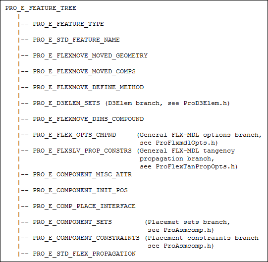
The element tree for the Move and Move-Copy feature is documented in the header file ProFlexMove.h, and is shown in the following figure:
Element Tree for Move and Move-Copy
Image
The following table describes the elements in the element tree for the Move and Move-Copy features:
Element ID
Data Type
Description
PRO_E_FEATURE_TYPE
PRO_VALUE_TYPE_INT
Specifies the type of feature.
PRO_E_STD_FEATURE_NAME
PRO_VALUE_TYPE_WSTRING
Specifies the name of the feature. The default value is Flex_Move.
PRO_E_FLEXMOVE_MOVED_GEOMETRY
Compound
Specifics the geometry to be moved.
PRO_E_FLEXMOVE_MOVED_COMPS
PRO_ELEM_TYPE_MULTI_VALUE
Note
The data type PRO_ELEM_ TYPE_MULTI_VALUE enables you to assign multiple values to the element, though the data type is not an array.
Optional element. This element is available only when you create the move feature at the assembly level. Specifies the collection of component references, that is, parts and subassemblies in an assembly, which are moved by the assembly level move feature.
PRO_E_FLEXMOVE_DEFINE_METHOD
PRO_VALUE_TYPE_INT
Mandatory element. Specifies the method to be used to move the entities. It takes the following values:
•  PRO_FLEXMOVE_DEF_METHOD_3D
_DRAG
—You can use the 3D transformation sets (in Creo Parametric interface using 3D Dragger) to define the flexible move feature.
•  PRO_FLEXMOVE_DEF_METHOD_DIMENSIONS—You can specify up to three constraining nonparallel linear dimensions or angular dimensions to define the flexible move feature.
•  PRO_FLEXMOVE_DEF_METHOD_CONSTRAINTS—You can specify component-like (assembly-like) constraints to define the flexible move feature.
PRO_E_D3ELEM_SETS
Array holder
Mandatory element when the definition method is PRO_FLEXMOVE_DEF_METHOD_3D_DRAG. An array holder of PRO_E_D3ELEM_SET elements.. The elements for 3D transformation sets are defined in ProD3Elem.h.
For more information, see the section 3D Transformation Set Feature.
PRO_E_FLEXMOVE_DIMS_COMPOUND
Compound
Mandatory element when the definition method is PRO_FLEXMOVE_DEF_METHOD_DIMENSIONS. Specifies the dimension references and arrays for the dimension definition method.
PRO_E_FLEX_OPTS_CMPND
Compound
Mandatory element that contains the flexible modeling geometry attachment options to attach the moved surfaces. Specifies the integer and chain collection type elements. The elements related to reattachment of geometry in flexible modeling are defined in ProFlxmdlOpts.h.
For more information, see the section Attachment Geometry Feature.
PRO_E_FLXSLV_PROP_CONSTRS
Array
Optional element. Specifies an array that contains the tangency conditions and the reference geometry elements for tangency propagation.
The elements related to propagation of tangency in flexible modeling are defined in ProFlexTanPropOpts.h. For more information, see the section Tangency Propagation.
PRO_E_COMPONENT_SETS
Array holder
Mandatory element when the definition method is PRO_FLEXMOVE_DEF_METHOD_CONSTRAINTS. Specifies the constraint sets. The elements for constraint sets are defined in ProAsmcomp.h. For more information, see the section Constraint Sets and Mechanism Connections of section Assembly: Assembling Components.
PRO_E_COMPONENT_CONSTRAINTS
Array holder
Mandatory element when the definition method is PRO_FLEXMOVE_DEF_METHOD_CONSTRAINTS. Specifies the constraints. The elements for constraints are defined in ProAsmcomp.h. For more information, see the section Placement Constraints of section Assembly: Assembling Components.
PRO_E_STD_FLEX_PROPAGATION
PRO_VALUE_TYPE_SELECTION
Optional element. Specifies a pattern or mirror recognition feature to propagate the move feature changes.
Moved Geometry
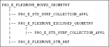
The feature PRO_E_FLEXMOVE_MOVED_GEOMETRY is a compound element that allows you to select the geometries to be moved and the geometries to be excluded.
PRO_E_FLEXMOVE_MOVED_GEOMETRY
Image
The following table lists the contents of PRO_E_FLEXMOVE_MOVED_GEOMETRY element.
Element ID
Data Type
Description
PRO_E_STD_SURF_COLLECTION_APPL
PRO_VALUE_TYPE_SELECTION
Mandatory element. Specifies the collection of surface sets of the geometries to be moved. It may also include surface regions.
PRO_E_FLEXMOVE_EXCLUDED_GEOMETRY
Compound
Optional element to exclude surfaces.
PRO_E_STD_SURF_COLLECTION_APPL
PRO_VALUE_TYPE_SELECTION
Optional element. Specifies the collection of surfaces from the move surfaces collector which should be excluded from the move operation.
PRO_E_FLEXMOVE_DTM_REF
PRO_ELEM_TYPE_MULTI_VALUE
Note
The data type PRO_ELEM_TYPE_MULTI_VALUE allows you to assign multiple values to the element, though the data type is not an array.
Optional element. Specifies the collection of datum entities that should be moved with the moved geometry.
Dimension Elements
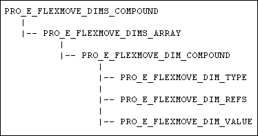
The element PRO_E_FLEXMOVE_DIMS_COMPOUND is a compound element that allows you to specify the dimensions to move the geometries.
PRO_E_FLEXMOVE_DIMS_COMPOUND
Image
The following table lists the contents of PRO_E_FLEXMOVE_DIMS_COMPOUND element. All the elements are mandatory for the PRO_FLEXMOVE_DEF_METHOD_DIMENSIONS definition method type.
Element ID
Data Type
Description
PRO_E_FLEXMOVE_DIMS_ARRAY
Array holder
Mandatory element. The dimensions array can contain up to three dimensions of PRO_FLEXMOVE_ DIM_TYPE_LINEAR type or a single dimension of PRO_FLEXMOVE_ DIM_TYPE_ANGULAR type.
PRO_E_FLEXMOVE_DIM_COMPOUND
Compound
Mandatory element. Specifies the constraining dimensions to move the geometries.
PRO_E_FLEXMOVE_DIM_REFS
PRO_ELEM_TYPE_MULTI
_VALUE
Mandatory element. Specifies two references for the given dimension. Out of the two selected references one must belong to the moved geometry and the other must belong to the geometry that is not affected by the move operation.
The valid values for reference selections are as follows:
•  Surface—SEL_3D_SRF
•  Line—SEL_3D_EDG, SEL_3D_CURVE, SEL_3D_AXIS
•  Points—SEL_3D_VERT, SEL_3D_PNT, SEL_CURVE_END
The valid combinations for reference selections are as follows:
•  Surface-Surface
•  Surface-Line
•  Surface-Point
•  Line-Line
•  Line-Point
PRO_E_FLEXMOVE_DIM_VALUE
PRO_VALUE_TYPE_DOUBLE
Mandatory element. Specifies the value of the linear or angular dimension.
The valid values are as follows:
•  Linear Dimensions—[-1e6, 1e6]
•  Angular Dimensions—[0, 360]
3D Transformation Set Feature
This section describes how to construct and access the element tree for 3D Transformation Set features. It also shows how to create, redefine, and access the properties of these features.
Introduction
The D3 element tree branch is used by features that use the 3D transformation steps, for example in the PRO_FEAT_FLEXMOVE feature type. See ProFlexMove.h. The 3D transformation steps are usually defined using the 3D Dragger in the Creo Parametric user interface.
Refer to the Creo Parametric Part Modeling Help for more information on placement and orientation references, and Degrees of Freedom.
The Element Tree for 3D Transformation Sets
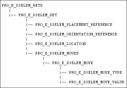
The element tree for the 3D Transformation Set feature is documented in the header file ProD3Elem.h, and is shown in the following figure:
Element Tree for 3D Transformation Sets
Image
The following table describes the elements in the element tree for the 3D Transformation Set feature:
Element ID
Data Type
Description
PRO_E_D3ELEM_SETS
Array holder
An array holder of PRO_E_D3ELEM_SET elements.
PRO_E_D3ELEM_SET
Compound
A compound element representing a single transformations set.
PRO_E_D3ELEM_PLACEMENT_REFERENCE
PRO_VALUE_TYPE_SELECTION
Optional element. Specifies the placement reference for the 3D transformation sets.
The valid values for placement reference selection are as follows:
•  Surface—SEL_3D_SRF
•  Line—SEL_3D_EDG, SEL_3D_CURVE, SEL_3D_AXIS
•  Points—SEL_3D_VERT, SEL_3D_PNT, SEL_CURVE_END
•  Coordinate System—SEL_3D_CSYS
Note
In case of an empty value for the placement reference, the default placement reference will be used.
PRO_E_D3ELEM_ORIENTATION_REFERENCE
PRO_VALUE_TYPE_SELECTION
Optional element. Specifies up to two references to define the orientation for the 3D transformation sets.
The valid values for orientation reference selection are as follows:
•  Surface—SEL_3D_SRF
•  Line—SEL_3D_EDG, SEL_3D_CURVE, SEL_3D_AXIS
•  Coordinate System—SEL_3D_CSYS
Note
In case of an empty value for the placement reference, the default placement reference will be used.
PRO_E_D3ELEM_LOCATION
PRO_VALUE_TYPE_INT
Optional element. Specifies whether the transformation set moves with the geometry for every move. It takes the following values:
•  PRO_D3_LOCATION_MOVING—This is the default value. The coordinate system of the transformation set moves with each move made in the set.
•  PRO_D3_LOCATION_FIXED—This value can be set only if the placement reference and the orientation reference are both selected to be the same coordinate system (SEL_3D_CSYS).
When this value is set, the transformation set's coordinate system retains its position and orientation during the move, only the selected geometry moves. The move step is defined in reference to this fixed coordinate system.
PRO_E_D3ELEM_MOVES
Array holder
An array holder of PRO_E_D3ELEM_MOVE element.
PRO_E_D3ELEM_MOVE
Compound
A compound element which represents a single move in the given set
PRO_E_D3ELEM_MOVE_TYPE
PRO_VALUE_TYPE_INT
Mandatory element. Specifies the move type to be used to move the geometry
This element takes the following values:
•  PRO_D3_MOVE_TYPE_SURF
—Specifies that the move is made to a UV coordinate on a surface, from its initial UV placement point on that surface.
Note
This move type is relevant only if the move set is placed on a surface.
To set and get the UV parameters use the functions:
  ProFeatureD3elemUvGet()
  ProFeatureD3elemUvSet()
•  PRO_D3_MOVE_TYPE_EDGE
—Specifies that the move is made to coordinate (ratio parameter) on an edge, from its initial placement on that edge. The position is recorded as a length ratio on the edge.
Note
This move type is relevant only if the move set is placed on an edge.
To set and get the position ratio use the functions:
  ProFeatureD3elemRatioGet()
  ProFeatureD3elemRatioSet()
•  PRO_D3_MOVE_TYPE_FREE
—Specifies the move using a transformation matrix. It stores the final 3D location of the moved geometry. To compute the final position of the moved geometry, the saved 3D location is used.
Note
This move type is relevant only if the placement reference and the orientation reference elements have default (empty) values.
To set and get the position delta matrix use the functions:
  ProFeatureD3elemMatrixGet()
  ProFeatureD3elemMatrixSet()
•  PRO_D3_MOVE_TYPE_FREETRF
—Specifies the move using a transformation matrix, similar to PRO_D3_MOVE_TYPE_FREE. It stores the transformation matrix. To compute the final position of the moved geometry, the saved transformation matrix is used.
Note
This move type is relevant only if the placement reference and the orientation reference elements have default (empty) values.
•  PRO_D3_MOVE_TYPE_
XMOVE
—Specifies the linear translation along the current coordinate system's X-vector.
•  PRO_D3_MOVE_TYPE_
YMOVE
—Specifies the linear translation along the current coordinate system's Y-vector.
•  PRO_D3_MOVE_TYPE_
ZMOVE
—Specifies the linear translation along the current coordinate system's Z-vector.
•  PRO_D3_MOVE_TYPE_XROTATE—Specifies the rotational angle along the current coordinate system's X-vector.
•  PRO_D3_MOVE_TYPE_YROTATE—Specifies the rotational angle along the current coordinate system's Y-vector.
•  PRO_D3_MOVE_TYPE_ZROTATE—Specifies the rotational angle along the current coordinate system's Z-vector.
PRO_E_D3ELEM_MOVE_VALUE
PRO_VALUE_TYPE_DOUBLE
Mandatory element. Specifies the translation distance or the rotational angle for the move command.
The valid values are as follows:
•  Linear Move types—[-1e6, 1e6]
•  Angular Move types—[0, 360]
Functions for the PRO_E_D3ELEM_MOVE_VALUE element
This section describes the functions to be used to set the move type for the element PRO_E_D3ELEM_MOVE_VALUE.
Functions Introduced:
The functions ProFeatureD3elemUvGet() and ProFeatureD3elemUvSet() get and set the position UV parameter for the PRO_E_D3ELEM_MOVE_VALUE element on a surface or plane.
Note
The functions ProFeatureD3elemUvGet() and ProFeatureD3elemUvSet() are relevant only when the element PRO_E_D3ELEM_MOVE_TYPE has its move value as PRO_D3_MOVE_TYPE_SRF.
The functions ProFeatureD3elemRatioGet() and ProFeatureD3elemRatioSet() get and set the position ratio for the PRO_E_D3ELEM_MOVE_VALUE element on an edge or entity.
Note
The functions ProFeatureD3elemRatioGet() and ProFeatureD3elemRatioSet() are relevant only when the element PRO_E_D3ELEM_MOVE_TYPE has its move value as PRO_D3_MOVE_TYPE_EDGE.
The functions ProFeatureD3elemMatrixGet() and ProFeatureD3elemMatrixSet() get and set the position delta matrix for the PRO_E_D3ELEM_MOVE_VALUE element.
Note
The functions ProFeatureD3elemMatrixGet() and ProFeatureD3elemMatrixSet() are relevant only when the element PRO_E_D3ELEM_MOVE_TYPE has its move value as PRO_D3_MOVE_TYPE_FREE.
Attachment Geometry Feature
This section describes how to construct and access the element tree for reattaching geometry when a flexible modeling feature modifies or transforms a geometry selection. It also shows how to create, redefine, and access the properties of the attachment features.
Introduction
When a geometry selection is transformed by a flexible modeling feature, you can reattach the geometry to the model in one of the following ways:
•  Extend the surfaces of the geometry selection and the neighboring geometry until they intersect each other, or until the hole where the geometry selection was originally located is closed and the transformed or modified geometry is reattached.
•  Create the side surfaces to close the gap between the moved geometry and the hole left in the model.
•  Recreate immediate neighboring surfaces maintaining tangency conditions, if the moved geometry and the immediate neighboring surfaces are tangent planes and circles.
The attachment element PRO_E_FLEX_OPTS_CMPND is seen in the following feature types:
•  PRO_FEAT_FLEXMOVE (See ProFlexMove.h)
•  PRO_FEAT_FLX_OGF (See ProFlexOffset.h)
•  PRO_FEAT_ANALYT_GEOM (See ProFlexMag.h)
•  PRO_FEAT_FLXATTACH (See ProFlexAttach.h)
•  PRO_FEAT_FLEXSUBST (See ProFlexSubstitute.h)
The Element Tree for Attachment Geometry Options
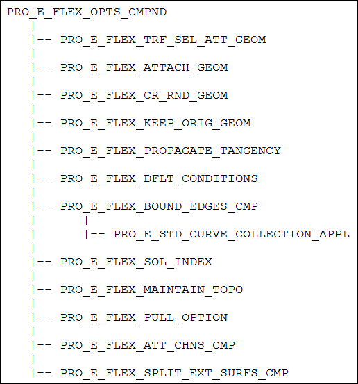
The element tree for the Attachment Geometry feature is documented in the header file ProFlxmdlOpts.h, and is shown in the following figure.
Element Tree for Attachment Geometry Options
Image
The following table describes the elements in the element tree for the Geometry Attachment feature:
Element ID
Data Type
Description
PRO_E_FLEX_OPTS_CMPND
Compound
Specifies the flexible modeling geometry reattachment options.
PRO_E_FLEX_TRF_SEL_ATT_GEOM
PRO_VALUE_TYPE_INTEGER
Mandatory element. Specifies whether the chamfers and rounds that attach the moved geometry to the model must also be transformed.
This element is relevant in PRO_FEAT_FLEXMOVE, PRO_FEAT_FLX_OGF, PRO_FEAT_FLEXSUBST, mirror feature and in patterning.
This element takes the following values:
•  PRO_FLXMDL_OPT_YES
•  PRO_FLXMDL_OPT_NO
When the value PRO_FLXMDL_OPT_NO is specified, the chamfers and rounds are removed and optionally recreated.
PRO_E_FLEX_ATTACH_GEOM
PRO_VALUE_TYPE_INTEGER
Mandatory element. Specifies whether to attach the moved geometry to the same quilt or solid it was detached from.
This element is relevant in PRO_FEAT_FLEXMOVE, PRO_FEAT_FLX_OGF and PRO_FEAT_ANALYT_GEOM.
This element takes the following values:
•  PRO_FLEXMODEL_OPT_YES—Attaches the moved geometry to same quilt or solid.
•  PRO_FLEXMODEL_OPT_NO—Creates a new separate quilt.
PRO_E_FLEX_CR_RND_GEOM
PRO_VALUE_TYPE_INTEGER
Mandatory element. Specifies whether to create a round geometry after the geometry selection is moved and reattached. This applicable for geometry selection that was originally attached by round geometry.
This element is relevant in PRO_FEAT_FLEXMOVE, PRO_FEAT_FLX_OGF, PRO_FEAT_ANALYT_GEOM and PRO_FEAT_FLEXSUBST.
This element takes the following values:
•  PRO_FLEXMODEL_OPT_YES
•  PRO_FLEXMODEL_OPT_NO
There are two cases here:
•  When PRO_E_FLEX_ATTACH_GEOM is set to PRO_FLEXMODEL_OPT_YES and PRO_E_FLEX_CR_RND_GEOM is set to following values:
  PRO_FLEXMODEL_OPT_YES—The rounds are recreated.
  PRO_FLEXMODEL_OPT_NO—The rounds are not recreated.
•  When PRO_E_FLEX_ATTACH_GEOM is set to PRO_FLEXMODEL_OPT_No the rounds are not reattached. However, in this case you can save the information about the attachment properties for the rounds. PRO_E_FLEX_CR_RND_GEOM is set to following values:
  PRO_FLEXMODEL_OPT_YES—The attachment information of the rounds is stored in intent objects. This information can be used by some other features.
  PRO_FLEXMODEL_OPT_NO—The attachment information of the rounds is not stored.
PRO_E_FLEX_KEEP_ORIG_
GEOM
PRO_VALUE_TYPE_INTEGER
Mandatory element. Specifies if the original geometry must be moved or a copy of the geometry should be moved.
This element is relevant in PRO_FEAT_FLEXMOVE and PRO_FEAT_FLEXSUBST.
This element takes the following values:
•  PRO_FLEXMODEL_OPT_YES
•  PRO_FLEXMODEL_OPT_NO
PRO_E_FLEX_PROPAGATE_TANGENCY
PRO_VALUE_TYPE_INTEGER
Mandatory element. Specifies if tangency must be maintained between the modified geometry and the neighboring geometry.
This element is relevant in PRO_FEAT_FLEXMOVE, PRO_FEAT_FLX_OGF and PRO_FEAT_ANALYT_GEOM.
This element takes the following values:
•  PRO_FLEXMODEL_OPT_YES
•  PRO_FLEXMODEL_OPT_NO
PRO_E_FLEX_DFLT_CONDITIONS
PRO_VALUE_TYPE_INTEGER
Mandatory element. Specifies if the default condition must be applied to the vertices of the dragged geometry. The vertices are selected by the system. The default condition is to fix the selected vertices. These vertices do not transform along with the dragged geometry.
This element is relevant in PRO_FEAT_FLEXMOVE, PRO_FEAT_FLX_OGF and PRO_FEAT_ANALYT_GEOM.
This element takes the following values:
•  PRO_FLEXMODEL_OPT_YES
•  PRO_FLEXMODEL_OPT_NO
PRO_E_FLEX_BOUND_EDGES_
CMP
Compound
This compound element collects the bounding edges.
PRO_E_FLEX_MAINTAIN_TOPO
PRO_VALUE_TYPE_INTEGER
Mandatory element. Specifies the option to maintain solution topology for generic flexible modeling features:
•  PRO_FEAT_FLEXMOVE
•  PRO_FEAT_FLX_OGF
•  PRO_FEAT_ANALYT_GEOM
•  PRO_FEAT_FLEXSUBST
•  PRO_FEAT_FLEXATTACH
This element has the following valid values:
•  PRO_FLXMDL_OPT_YES—The application generates feature geometry that is topologically similar to the solution stored in the element PRO_E_FLEX_SOL_INDEX. If such a solution cannot be created, the feature will fail.
•  PRO_FLXMDL_OPT_NO—The application generates geometry that is topologically similar to the solution stored in the element PRO_E_FLEX_SOL_INDEX. If such a solution cannot be created, the application tries to create other successful solution. If the application cannot create any other solution for the changed model, the feature fails.
Note
You cannot select the solution interactively using Creo TOOLKIT applications.
PRO_E_STD_CURVE_COLLECTION_APPL
Chain
Optional element. Collects the bounding edges from the geometry list to which the primary feature geometry will be reattached. The bounding edges are used as the limiting edges for the feature reattachment solutions. The edges that belong to the primary feature references cannot be used as bounding edges.
Note
The information on the chosen solution is stored in the element PRO_E_FLEX_SOL_INDEX. This element is not accessible by Creo TOOLKIT, under which a default solution will be always used.
This element is relevant in PRO_FEAT_FLEXMOVE, PRO_FEAT_FLX_OGF, PRO_FEAT_ANALYT_GEOM, PRO_FEAT_FLEXSUBST and PRO_FEAT_FLEXATTACH.
PRO_E_FLEX_PULL_OPTION
PRO_VALUE_TYPE_INTEGER
Mandatory element. Specifies the attachment option by which the moved geometry will be attached to the model. The bounding chain edges selected in the element PRO_E_FLEX_BOUND
_EDGES_CMP
are used for the reattachment of moved geometry.
This element takes the following values:
•  PRO_FLEXMODEL_PULL_NONE—The moved geometry is attached using the default method or according to the contents of the Create side surfaces and Extend side surfaces chain collectors which decide the attachment method.
Refer to the section Default Method for the Pull Option for more information on the default method.
•  PRO_FLEXMODEL_PULL_CREATE_SURFS—The moved geometry is reattached to the same quilt or solid it was detached from using the Create side surfaces option. The moved surfaces are attached to the model by creating surfaces that connect the original contour to the final contour of the moved surface.
•  PRO_FLEXMODEL_PULL_EXTEND_SURFS—The moved geometry is reattached to the same quilt or solid it was detached from using the Extend side surfaces option. The moved surfaces are attached to the model by extending and intersecting the moved surfaces and their neighboring surfaces.
This element is relevant in PRO_FEAT_FLEXMOVE.
PRO_E_FLEX_ATT_CHNS_CMP
Compound
Non-default edge chain collector.
PRO_E_FLEX_SIDE_SRFS_CMP
Compound
Edge chain collector for Create side surfaces.
PRO_E_STD_CURVE_COLLECTION_APPL
Chain Collection
Optional element. Collects the edge chains for which the attachment option will be changed from default to Create side surfaces. Here side surfaces will be created to close the gap between the moved geometry and the hole left in the model.
This element is relevant in PRO_FEAT_FLEXMOVE, PRO_FEAT_FLX_OGF and PRO_FEAT_ANALYT_GEOM.
You can select the edges and intent edges that belong to the intersection between the geometry selection and the neighboring geometry.
PRO_E_FLEX_EXT_INT_CMP
Compound
Edge chain collector for Extend and intersect.
PRO_E_STD_CURVE_COLLECTION_APPL
Chain Collection
Optional element. Collects the edge chains for which the attachment option will be changed from default to Extend and intersect. Here the surfaces of the geometry selection and the neighboring geometry are extended until they intersect each other.
This element is relevant in PRO_FEAT_FLEXMOVE, PRO_FEAT_FLX_OGF and PRO_FEAT_ANALYT_GEOM.
You can select the edges and intent edge that belong to the intersection between the geometry selection and the neighboring geometry, and do not belong to the side surface set.
PRO_E_FLEX_SPLIT_EXT_
SURFS_CMP
Compound
Collector to split the extending surface area.
This element is relevant in PRO_FEAT_FLEXMOVE and PRO_FEAT_FLX_OGF.
PRO_E_FLEX_EXT_SRFS_CMP
Compound
Compound collector for extending surfaces set to be split.
PRO_E_STD_SURF_COLLECTION_APPL
Surface Collection
Optional element. This element is used with the splitting surfaces set and the flip options. Collects the extending surfaces that will be split by the splitting surfaces. You can select the surfaces that belong to the flexible modeling feature's references surface set.
This element is relevant in PRO_FEAT_FLEXMOVE and PRO_FEAT_FLX_OGF.
This element is irrelevant in PRO_FEAT_ANALYT_GEOM as the reference surface is the only possible extending surface.
PRO_E_FLEX_SPT_SRFS_CMP
Compound
Compound collector for splitting surfaces set.
PRO_E_STD_SURF_COLLECTION_APPL
PRO_VALUE_TYPE_SELECTION
Optional element. This element is used with the extending surfaces set. Collects surfaces that will be extended and used to split the extending surfaces. You can select the surfaces which belong to the same solid or quilt that contains the surfaces being modified.
This element is relevant in PRO_FEAT_FLEXMOVE, PRO_FEAT_FLX_OGF and PRO_FEAT_ANALYT_GEOM.
PRO_E_FLEX_FLIP_SPLIT
_DIR
PRO_VALUE_TYPE_INT
Optional element. This element is used with the extending and splitting surfaces sets. Flips the side of the extending surfaces.
This element is relevant in PRO_FEAT_FLEXMOVE, PRO_FEAT_FLX_OGF and PRO_FEAT_ANALYT_GEOM.
This element takes the following values:
•  PRO_FLEXMODEL_OPT_YES
•  PRO_FLEXMODEL_OPT_NO
Default Method for the Pull Option
When the value of the element PRO_E_FLEX_PULL_OPTION is set to PRO_FLEXMODEL_PULL_NONE the moved geometry is attached using either of the following options:
•  Default method
•  According to the contents of the Create side surfaces and Extend side surfaces chain collectors
This section describes the default method for the Pull option in detail.
The geometry of the modified surface and the neighboring surface decides the default method by which the surfaces will be attached:
•  If the modified surface and the neighboring surface are not tangential to each other, the surfaces are extended until they intersect, that is, they are attached using the Extend and intersect option.
•  If the modified surface and the neighboring surface are tangential to each other, the moved geometry is attached in one of the following ways:
  If the modified surface is of any type and the neighboring surface is a round surface, the surfaces are attached in the following way:
  The round is removed.
  The surfaces are attached using the Extend and intersect option.
  The round is recreated.
  If the modified surface is of any type and the neighboring surface is not a round surface, the surfaces are attached in either of the following ways:
  The surfaces are attached by creating side surfaces, that is, by using the Create side surfaces option.
  If the side wall construction fails due to some geometrical reason, for example, self-intersection, then the default option is reset to Extend and intersect.
  If modified surface and the neighboring surface are analytic, that is, cylindrical, planar, conical, toroidal, or tabulated cylinder and the tangency propagation is set to No, the surfaces are attached in either of the following ways:
  If the neighboring surface is identified as a round, then the attachment is similar to the above mentioned round surface.
  If the neighboring surface is not a round surface, then the surfaces are attached using the Create side surfaces option.
  If modified surface and the neighboring surface are analytic, that is, cylindrical, planar, conical, toroidal, or tabulated cylinder, the tangency is along an isoline and the tangency propagation is set to Yes, the surfaces are attached in either of the following ways:
  If the neighboring surface is identified as a round, then the attachment is similar to the above mentioned round surface.
  If the neighboring surface is not a round surface, the neighboring surface is dragged to maintain the tangency between the surfaces.
Refer to the section Tangency Propagation for more information on tangency propagation and dragged geometry.
Offset Geometry Feature
This section describes how to construct and access the element tree for Offset Geometry feature. It also shows how to create, redefine, and access the properties of this feature.
Introduction
The Offset Geometry feature allow you to offset a geometry selection that belongs to a solid geometry or to a quilt, and reattach it back to the solid or quilt. You can offset the following geometry selection:
•  Any surface collection.
•  An intent surface.
•  Any combination of the above geometries.
A offset feature will act on a single geometry selection. To offset a different geometry selection, a new Offset Geometry feature must be created.
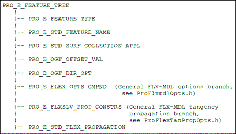
The Element Tree for Offset Geometry
The element tree for the Offset Geometry feature is documented in the header file ProFlexOffset.h, and is shown in the following figure.
Element Tree for Offset Geometry
Image
The following table describes the elements in the element tree for the Offset Geometry feature:
Element ID
Data Type
Description
PRO_E_FEATURE_TYPE
PRO_VALUE_TYPE_INT
Specifies the type of feature.
PRO_E_STD_FEATURE_NAME
PRO_VALUE_TYPE_WSTRING
Specifies the name of the feature. The default value is Offset_Geom.
PRO_E_STD_SURF_COLLECTION_APPL
PRO_VALUE_TYPE_SELECTION
Mandatory element. Specifies the collection of surfaces to offset.
PRO_E_OGF_OFFSET_VAL
PRO_VALUE_TYPE_DOUBLE
Mandatory element. Specifies the offset value. It takes value between [-1.00e+06, 1.00e+06].
PRO_E_OGF_DIR_OPT
PRO_VALUE_TYPE_INT
Mandatory element. Specifies the direction of offset. It takes the following values:
•  PRO_FLXOGF_DIR_NORMAL—Offsets the geometry normal to the selected surface.
•  PRO_FLXOGF_DIR_FLIP—Flips the direction of offset.
PRO_E_FLEX_OPTS_CMPND
Compound
Mandatory element that contains the flexible modeling geometry attachment options to attach the surfaces offset. Specifies the integer and chain collection type elements. The elements related to reattachment of geometry in flexible modeling are defined in ProFlxmdlOpts.h.
For more information, see the section Attachment Geometry Feature.
PRO_E_FLXSLV_PROP_CONSTRS
Array
Optional element. Specifies an array that contains the tangency conditions and the reference geometry elements for tangency propagation. This element must be specified when the element PRO_E_FLEX_PROPAGATE_TANGENCY is set to PRO_FLEXMODEL_OPT_YES in the header file ProFlxmdlOpts.h.
The elements related to propagation of tangency in flexible modeling are defined in ProFlexTanPropOpts.h. For more information, see the section Tangency Propagation.
PRO_E_STD_FLEX_PROPAGATION
PRO_VALUE_TYPE_SELECTION
Optional element. Specifies a pattern or mirror recognition feature to propagate the offset geometry feature changes.
Modify Analytic Surface Feature
This section describes how to construct and access the element tree for Modify Analytic Surface feature for flexible modeling. It also shows how to create, redefine, and access the properties of this feature.
Introduction
The Modify Analytic Surface feature allows you to modify the analytic surfaces. The modification is done by creating and modifying basic dimensions that define each surface type.
The following analytic surfaces can be modified:
•  Cylinder—The axis remains fixed and the radius can be modified.
•  Torus—The axis of revolution of the circle remains fixed. The radius of the circle and the distance (radius) from the center of the circle to the axis of revolution can be modified.
•  Cone—The axis and vertex of the cone remain fixed, and the angle can be modified.
The Element Tree for Modify Analytic Surface
The element tree for the Modify Analytic Surface feature is documented in the header file ProFlexMag.h, and is shown in the following figure.
Element Tree for Modify Analytic Surface
Image
The following table describes the elements in the element tree for the Modify Analytic Surface feature:
Element ID
Data Type
Description
PRO_E_FEATURE_TYPE
PRO_VALUE_TYPE_INT
Specifies the type of feature.
PRO_E_STD_FEATURE_NAME
PRO_VALUE_TYPE_WSTRING
Specifies the name of the feature. The default value is MODIFY_ANALYTIC_SURFACE.
PRO_E_STD_SURF_COLLECTION_APPL
PRO_VALUE_TYPE_SELECTION
Mandatory element. Specifies the collection of analytical surface sets to be modified. The valid surface selections are: cylindrical, conical or toroidal surfaces.
Note
You can specify only one reference surface or surface region at a time in this element.
PRO_E_STD_FLEX_PROPAGATION
PRO_VALUE_TYPE_SELECTION
Optional element. Specifies a pattern or mirror recognition feature to propagate the modified analytic surface feature changes.
PRO_E_FLEX_OPTS_CMPND
Compound
Mandatory element that contains the flexible modeling geometry attachment options to attach the modified surfaces. Specifies the integer and chain collection type elements. The elements related to reattac of geometry in flexible modeling are defined in ProFlxmdlOpts.h.
For more information, see the section Attachment Geometry Feature.
PRO_E_FLXSLV_PROP_CONSTRS
Array
Optional element. Specifies an array that contains the tangency conditions and the reference geometry elements for tangency propagation. This element must be specified when the element PRO_E_FLEX_PROPAGATE_TANGENCY is set to PRO_FLEXMODEL_OPT_YES in the header file ProFlxmdlOpts.h.
The elements related to propagation of tangency in flexible modeling are defined in ProFlexTanPropOpts.h. For more information, see the section Tangency Propagation.
PRO_E_MAG_ANGLE_VAL
PRO_VALUE_TYPE_DOUBLE
Mandatory element for conic surface. Specifies the angle of the conic surface.
The element takes angular value between [0.5, 89] degrees.
PRO_E_MAG_RADII_VAL
PRO_VALUE_TYPE_DOUBLE
Mandatory element for cylindrical and a toroidal surface.
For cylindrical surface, the element specifies the radius of the cylindrical surface.
For torodial surface, the element specifies the radius of revolution of the toroidal surface.
The element takes value between [0, 1.00e+06].
PRO_E_MAG_RADII2_VAL
PRO_VALUE_TYPE_DOUBLE
Mandatory element for conic surface. Specifies the circle radius of the toroidal surface.
The element takes value between [0, 1.00e+06].
Tangency Propagation
This section describes how to construct and access the elements for propagating tangency in a flexible modeling feature.
Introduction
When geometry is modified with Move, Offset, or Modify Analytic command, you can maintain the tangency between the modified geometry and the neighboring geometry. To maintain the tangency, the neighboring geometry may be modified, though it was not selected for modification. The geometry that is included during tangency propagation is defined as dragged geometry. The dragged geometry is modified in such a way that it always remains tangential to the directly modified geometry. The tangency propagation stops when the application recognizes a surface that is round or chamfer. The chamfer or round surface, except variable rounds, is recreated after the geometry is modified. The round and chamfer geometry are called connecting geometry.
Depending on the type of round surface, the tangency may or may not be propagated. The rounds are of the following types:
•  Rounds that can be propagated. Tangency propagation can be forced to be carried through and continue onto adjacent tangent geometry.
•  Rounds that cannot be propagated. The tangency stops and cannot be forced to go further.
•  Rounds that cannot be recreated. These are mainly the variable rounds. Variable rounds can be removed but cannot be recreated.
•  Interfering rounds. These are rounds that do not connect transformed or dragged geometry to the rest of the model but have to be removed and recreated to accommodate the changes in the transformed geometry, dragged geometry, and other rounds.
The round or chamfer surfaces connect the directly modified geometry and the dragged surfaces to the background geometry. The background geometry is the base geometry that is not modified.
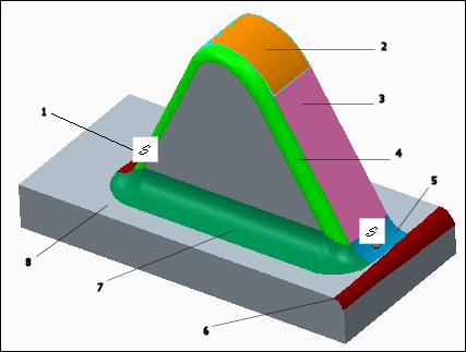
The modified, dragged, connecting, fixed, and background geometry are displayed in different colors during modification in the Creo Parametric user interface as shown in the figure below:
Image
1—Default vertices are automatically created when you propagate tangency
2—Directly modified geometry
3—Dragged geometry
4—Rounds that cannot propagated
5—Rounds that can be propagated
6—Rounds that cannot be recreated
7—Interfering rounds
8—Background geometry
You can control the changes in geometry during tangency propagation by specifying the tangency constraints. During tangency propagation the fixed vertex constraints are also considered. The tangency constraint is applied on a reference geometry that can either be the dragged geometry or the connecting geometry, or both. Refer to Creo Flexible Modeling Help for more information.
To work with tangency propagation, you must set the value of the element PRO_E_FLEX_PROPAGATE_TANGENCY to PRO_FLEXMODEL_OPT_YES. The element is defined in the header file ProFlxmdlOpts.h.
The element PRO_E_FLXSLV_PROP_CONSTRS is used to set the conditions that controls the changes in geometry during tangency propagation. It is seen in the following feature types:
•  PRO_FEAT_FLEXMOVE (See ProFlexMove.h)
•  PRO_FEAT_FLX_OGF (See ProFlexOffset.h)
•  PRO_FEAT_ANALYT_GEOM (See ProFlexMag.h)
The Element Tree for Tangency Propagation
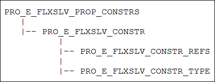
The element tree for the Tangency Propagation is documented in the header file ProFlexTanPropOpts.h, and is shown in the following figure.
Element Tree for Tangency Propagation
Image
The following table describes the elements in the element tree for the Tangency Propagation:
Element ID
Data Type
Description
PRO_E_FLXSLV_PROP_CONSTRS
Array
Specifies an array of conditions that control the tangency propagation.
PRO_E_FLXSLV_CONSTR
Compound
Mandatory element. Specifies a single condition for tangency along with the reference geometry.
PRO_E_FLXSLV_CONSTR_REFS
PRO_VALUE_TYPE_SELECTION
Mandatory element. Specifies the selection of reference geometry.
PRO_E_FLXSLV_CONSTR_TYPE
PRO_VALUE_TYPE_INTEGER
Mandatory element. Specifies a condition that sets constraint on the neighboring surfaces during the propagation of tangency. The valid values are defined in the enumerated data type ProFlxmdlPropOptFlag. Refer to section Setting Conditions for Tangency Propagation for more information on tangency conditions.
Setting Conditions for Tangency Propagation
You can set the conditions depending on geometry type that must be considered during tangency propagation. The conditions are specified using the enumerated data type ProFlxmdlPropOptFlag. The valid values are:
•  PRO_FLXSLV_CONSTR_TYPE_FIXED—Specifies that the reference geometry must be fixed. Tangency is not maintained between the modified geometry and the neighboring geometry. You can set the value for following types of geometry:
  Planar surface
  Cylindrical surface
  Conical surface
  Toroidal surface
  Spherical surface
  Tabulated cylinder
  Surface of revolution
  Round surface
  Edge (surface isoline) on the surface
  Vertex on the surface
Note
You can specify the condition PRO_FLXSLV_CONSTR_TYPE_FIXED while manipulating the geometry of parts, using the Creo Flexible Modeling commands, even if the value of PRO_E_FLEX_PROPAGATE_TANGENCY is set to PRO_FLEXMODEL_OPT_NO. Here the reference round and chamfer geometry are not considered as rounds and chamfers.
•  PRO_FLXSLV_CONSTR_TYPE_FIX_AXIS—Specifies that the axis of the reference geometry must be fixed. You can set the value for following types of geometry:
  Cylindrical surface
  Conical surface
  Toroidal surface
  Spherical surface
  Surface of revolution
•  PRO_FLXSLV_CONSTR_TYPE_FIX_CNTR—Specifies that the center of the reference geometry must be fixed. You can set the value for following types of geometry:
  Toroidal surface
  Spherical surface
•  PRO_FLXSLV_CONSTR_TYPE_FIX_NORM—Specifies that the reference geometry must be normal to the directly modified geometry. You can set the value for following type of geometry:
  Planar surface
•  PRO_FLXSLV_CONSTR_TYPE_CONST_R1—Specifies that the minor radius of reference geometry must be constant. You can set the value for following types of geometry:
  Cylindrical surface
  Toroidal surface—The minor diameter is kept constant.
  Spherical surface
•  PRO_FLXSLV_CONSTR_TYPE_CONST_R2—Specifies that the major radius of reference geometry must be constant. You can set the value for following type of geometry:
  Toroidal surface
•  PRO_FLXSLV_CONSTR_TYPE_CONST_ANG—Specifies that the angle between the reference geometry and directly modified geometry must be constant. You can set the value for following type of geometry:
  Conical surface
•  PRO_FLXSLV_CONSTR_TYPE_FIX_POLE—Specifies that the position of the pole in the reference geometry must be fixed. You can set the value for following type of geometry:
  Conical surface
•  PRO_FLXSLV_CONSTR_TYPE_PRPG_THRU—Specifies that the tangency must be propagated till the last available round surface or till the surface after which the tangency will break.
  Round surface
  Cylindrical surface
•  PRO_FLXSLV_CONSTR_TYPE_FIX_RNDEDG_PNT—Specifies that the endpoint (vertex) on the edge of the reference geometry must be fixed. You can set the value for following type of geometry:
  Round surface
•  PRO_FLXSLV_CONSTR_FIX_WITH_TNGCY—Specifies that the tangency must be maintained between the modified geometry and the neighboring dragged geometry, and further between the neighboring dragged geometry and connecting geometry. You can set the value for following types of geometry:
  Planar surface
  Cylindrical surface
  Conical surface
  Toroidal surface
  Spherical surface
  Tabulated cylinder
  Surface of revolution
  Round surface
  Edge (surface isoline) on the surface
  Vertex on the surface
•  PRO_FLXSLV_CONSTR_TYPE_CONST_R—Specifies that the radius of reference geometry must be constant. You can set the value for following types of geometry:
  Cylindrical surface
  Spherical surface
•  PRO_FLXSLV_CONSTR_TYPE_KEEP_SPHERICAL—Specifies that the shape of the sphere does not change, though the radius can change. You can set the value for following types of geometry:
  Spherical surface
Mirror Feature
This section describes how to construct and access the element tree for Mirror feature for flexible modeling. It also shows how to create, redefine, and access the properties of this feature.
Introduction
The Mirror feature allows you to mirror a selected set of geometry about a plane. You can either attach the mirrored geometry to the solid or quilt from which it was created or keep it detached.
If the geometry selection for the mirror feature includes or is attached by round geometry, then the round geometry can be recreated in the new mirrored location.
Note
The group header of the Mirror feature behaves as a standard feature. You can extract the header element tree in Creo TOOLKIT.
The Element Tree for Mirror
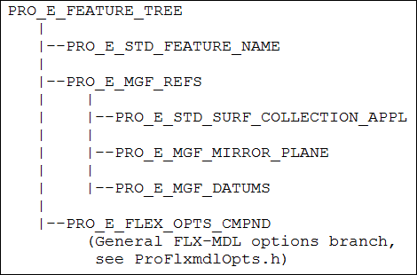
The element tree for the Mirror feature is documented in the header file ProFlexMirror.h, and is as shown in the following figure:
Element Tree for Mirror
Image
The following table describes the elements in the element tree for the Mirror feature:
Element ID
Data Type
Description
PRO_E_STD_FEATURE_NAME
PRO_VALUE_TYPE_WSTRING
Specifies the name of the feature. The default value is Mirror_Geometry.
PRO_E_MGF_REFS
Compound
Compound element that specifics the geometry, curves, and datums to be mirrored.
PRO_E_STD_SURF_COLLECTION_APPL
PRO_VALUE_TYPE_SELECTION
Mandatory element. Specifies the collection of surface sets of the geometry to be mirrored.
PRO_E_MGF_MIRROR_PLANE
PRO_VALUE_TYPE_SELECTION
Mandatory element. Specifies the datum plane or intent datum plane about which the geometry will be mirrored.
PRO_E_MGF_DATUMS
PRO_VALUE_TYPE_SELECTION
Optional element. Specifies the collection of curves and datum entities to be mirrored.
PRO_E_FLEX_OPTS_CMPND
Compound
Mandatory element that contains the Creo Flexible Modeling geometry attachment options to attach the mirrored surfaces. Specifies the integer and chain collection type elements. The elements related to reattachment of geometry in flexible modeling are defined in ProFlxmdlOpts.h.
For more information, see the section Attachment Geometry Feature.
Substitute Feature
This section describes how to construct and access the element tree for Substitute feature. It also shows how to create, redefine, and access the properties of this feature.
Introduction
The Substitute feature allows you to replace a geometry selection that belongs to a solid geometry or a quilt with replacing surfaces. The replacing surfaces are attached to the solid or quilt, and any round geometry between the geometry selection. The model is recreated after the replacing geometry is attached.
You can substitute the following geometry selection:
•  Any surface collection.
•  An intent surface.
•  Any combination of the above geometries.
•  Any one-sided edges on surfaces or quilts.
All the surfaces and one-sided edges in the geometry selection must belong to the same solid geometry or to the same quilt. The geometry selection must not be tangential to the neighboring geometry, or should be attached to the neighboring geometry with round geometry.
The replacing surfaces must be large enough to attach to the extension of the neighboring geometry, without the need to extend the replacing surfaces.
After substitution, the replacing surfaces that define the one-sided edge loops are extended and trimmed so that the resulting edges lie on the substituting geometry.
Refer to the Creo Flexible Modeling Help for more information.
The Element Tree for Substitute
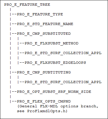
The element tree for the Substitute feature is documented in the header file ProFlexSubstitute.h, and is shown in the following figure.
Element Tree for Substitute
Image
The following table describes the elements in the element tree for the Substitute feature:
Element ID
Data Type
Description
PRO_E_FEATURE_TYPE
PRO_VALUE_TYPE_INT
Mandatory element. Specifies the type of feature. The value of this feature must be PRO_FEAT_FLEXSUBST.
PRO_E_STD_FEATURE_NAME
PRO_VALUE_TYPE_WSTRING
Specifies the name of the feature. The default value is Substitute.
PRO_E_CMP_SUBSTITUTED
Compound
Compound element for surfaces to be substituted.
PRO_E_FLXSUBST_METHOD
PRO_VALUE_TYPE_INT
Specifies which kind of geometry must be substituted. The valid geometry types are:
•  PRO_FLEXSUBST_SURFACES—Specifies that surfaces must be substituted.
•  PRO_FLEXSUBST_LOOPS—Specifies that one-sided edges must be substituted.
PRO_E_STD_SURF_COLLECTION_APPL
PRO_VALUE_TYPE_SELECTION
Mandatory element for PRO_FLEXSUBST_SURFACES. Specifies the collection of surfaces that will be replaced by the substituting surfaces.
PRO_E_FLXSUBST_EDGELOOPS
PRO_VALUE_TYPE_SELECTION
Mandatory element for PRO_FLEXSUBST_LOOPS. Specifies the collection of one-sided edges that will be replaced by the substituting surfaces.
PRO_E_CMP_SUBTITUTING
Compound
Compound element for substituting surfaces.
PRO_E_STD_SURF_COLLECTION_APPL
PRO_VALUE_TYPE_SELECTION
Mandatory element. Specifies the collection of substituting surfaces.
PRO_E_OPT_SUBST_SRF
_NORM_SIDE
PRO_VALUE_TYPE_BOOLEAN
Mandatory element. Specifies the direction of the normal vectors of the substituting surfaces.
This element takes the following values:
•  PRO_B_TRUE—Specifies that the side 1 is direction of normal vector.
•  PRO_B_FALSE—Specifies that the side 2 is direction of normal vector.
PRO_E_FLEX_OPTS_CMPND
Compound
Mandatory element that contains the flexible modeling geometry attachment options to attach the substituting surfaces. Specifies the integer and chain collection type elements. The elements related to reattachment of geometry in flexible modeling are defined in ProFlxmdlOpts.h.
For more information, see the section Attachment Geometry Feature.
Planar Symmetry Recognition Feature
This section describes how to construct and access the element tree for Planar Symmetry Recognition feature. It also shows how to create, redefine, and access the properties of this feature.
Introduction
The Planar Symmetry Recognition feature allows you to identify and modify geometry that is symmetric with respect to a plane. The modifications made to the geometry on one side are automatically propagated to the other side and the symmetry is kept.
The Planar Symmetry Recognition feature identifies symmetrical geometry in the following ways:
•  You can collect two seed surfaces or surface regions that are symmetric. The feature computes the plane of symmetry, and finds all pairs of neighboring surfaces and surface regions which are symmetric with respect to the symmetry plane. The propagation ends when non-symmetric neighboring surfaces are found.
The two seed surfaces or regions must belong to:
  The solid geometry.
  A single quilt.
  Two quilts.
•  You can collect a seed surface or surface region and a plane of symmetry. The feature finds the mirror image of the seed surface or surface region and, finds all the pairs of neighboring surfaces and surface regions which are symmetric with respect to the symmetry plane.
According to the correspondence between the geometry of the symmetrical members, the following variation of planar symmetry recognition are possible:
•  Identical—There is exact correspondence between the surfaces of the symmetrical members as well as between the intersection edges defined by these members and the surrounding geometry.
•  Similar—There is exact correspondence between the surfaces of the symmetrical members, but there is no exact correspondence between the intersection edges defined by these members and the surrounding geometry. The number of intersection loops must be the same, but the type of edges, number of edges in each intersection loop and the intersected model surfaces do not have to be the same.
Note
The group header of the Planar Symmetry Recognition feature behaves as a standard feature. You can extract the header element tree in Creo TOOLKIT.
The Element Tree for Planar Symmetry Recognition Feature
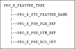
The element tree for the Planar Symmetry Recognition feature is documented in the header file ProSymmetryRecognition.h, and is shown in the following figure:
Element Tree for Planar Symmetry Recognition Feature
Image
The following table describes the elements in the element tree for the Planar Symmetry Recognition feature:
Element ID
Data Type
Description
PRO_E_STD_FEATURE_NAME
PRO_VALUE_TYPE_WSTRING
Specifies the name of the feature. The default value is Mirror_Recognition.
PRO_E_PSR_PLN_REF
PRO_VALUE_TYPE_SELECTION
Mandatory element. Specifies the collection of two seed surfaces or one seed surface and the symmetry mirror plane.
PRO_E_PSR_DTM_REF
PRO_VALUE_TYPE_SELECTION
Optional element. Specifies the collection of datums and curve chains that will be included in the symmetry recognition.
PRO_E_PSR_RCG_OPT
PRO_VALUE_TYPE_INT
Mandatory element. Specifies the type of symmetrical geometry to be recognized: Identical or Similar.
This element takes the following values:
•  PRO_PSR_IDENTICAL
•  PRO_PSR_SIMILAR
Attach Feature
This section describes how to construct and access the element tree for Attach feature. It also shows how to create, redefine, and access the properties of this feature.
Introduction
The Attach feature allows you to attach open quilts to solid or quilt geometry, if the open quilt does not intersect the solid or quilt geometry. You can select an open quilt and attach it to another quilt or solid geometry within the same model. You can also select two open quilts within the same model which do not intersect and attach them.
This feature is useful in case of UDF placement when the geometry of the UDF does not intersect the part.
The Element Tree for Attach Feature
The element tree for the Attach feature is documented in the header file ProFlexAttach.h, and is shown in the following figure:
Attach Feature Element Tree
Image
The following table describes the elements in the element tree for the Attach feature:
Element ID
Data Type
Description
PRO_E_FEATURE_TYPE
PRO_VALUE_TYPE_INT
Mandatory element. Specifies the type of feature. The value of this feature must be PRO_FEAT_ATTACH.
PRO_E_STD_FEATURE_NAME
PRO_VALUE_TYPE_WSTRING
Specifies the name of the feature. The default value is Attach_1.
PRO_E_REF_ATTACH_PRIM_QLT
PRO_VALUE_TYPE_SELECTION
Mandatory element. Specifies the primary open quilt to be attached to another quilt. The primary quit will be extended or trimmed during the attachment.
PRO_E_REF_ATTACH_MERG_QLT
PRO_VALUE_TYPE_SELECTION
Optional element. Specifies the merge quilt or solid geometry upto which the primary quilt can be extended or trimmed.
PRO_E_OPT_ATTACH_OPER
PRO_VALUE_TYPE_BOOLEAN
Mandatory element. Specifies whether to attach the primary quilt to the merge quilt or solid geometry.
This element takes the following values:
•  PRO_B_TRUE—Specifies that the primary quilt must not be attached.
•  PRO_B_FALSE—Specifies that the primary quilt must be attached.
PRO_E_OPT_ATTACH_RMV_MAT
PRO_VALUE_TYPE_BOOLEAN
This element is available when the element PRO_E_REF_ATTACH_MERG_QLT has no reference geometry specified. Specifies if material must be added or removed.
This element takes the following values:
•  PRO_B_TRUE—Specifies that the material must be removed.
•  PRO_B_FALSE—Specifies that the material must be added.
PRO_E_OPT_ATTACH_PQ_DIR
PRO_VALUE_TYPE_BOOLEAN
This element is available when the element PRO_E_OPT_ATTACH_OPER has its value as PRO_B_FALSE. Specifies the side of the quilt that must be included in the merged quilt
This element takes the following values:
•  PRO_B_TRUE—Specifies that the second side of the quilt must be merged.
•  PRO_B_FALSE—Specifies that the first side of the quilt must be merged.
PRO_E_OPT_ATTACH_MGQ_DIR
PRO_VALUE_TYPE_BOOLEAN
This element is available when the element PRO_E_OPT_ATTACH_OPER has its value as PRO_B_TRUE and the element PRO_E_REF_ATTACH_MERG_QLT has reference geometry specified. Specifies the direction in which the material should be added or removed in the primary quilt.
This element takes the following values:
•  PRO_B_TRUE—Specifies that the material must be added or removed from the second side.
•  PRO_B_FALSE—Specifies that the material must be added or removed from the first side.
PRO_E_OPT_ATTACH_PIO
PRO_VALUE_TYPE_BOOLEAN
Specifies if the quilt should be attached to the model geometry in the same way as it was attached previously by using the attachment information stored in the intent objects.
PRO_E_OPT_ATTACH_RNDCH
PRO_VALUE_TYPE_BOOLEAN
Specifies if the round or chamfer geometry of the quilt should be attached using the attachment information stored in the intent objects.
PRO_E_FLEX_OPTS_CMPND
Compound
Mandatory element that contains the flexible modeling geometry attachment options to attach the substituting surfaces. Specifies the integer and chain collection type elements. The elements related to reattachment of geometry in flexible modeling are defined in ProFlxmdlOpts.h.
For more information, see the section Attachment Geometry Feature.
Example 1: Creating a Flexible Model Feature
The sample code in UgFlexModelCreate.c located at <creo_toolkit_loadpoint>/protk_appls/pt_userguide/ptu_featcreat shows how to create a Creo Flexible Modeling feature.