Round Feature
Feature Element Tree for Round Feature
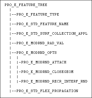
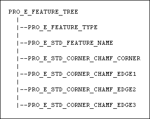
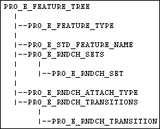
The element tree for a round is documented in the header file ProRound.h, and has a simple structure. The following figure demonstrates the feature element tree structure:
Feature Element Tree for Round
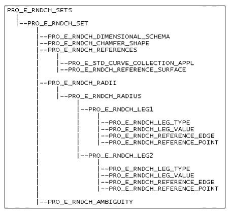
PRO_E_RNDCH_SETS
PRO_E_RNDCH_RADIUS
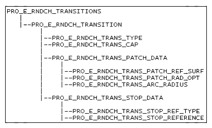
PRO_E_RNDCH_TRANSITIONS
The following list details special information about the elements in this tree:
| • | PRO_E_FEATURE_TYPE—Specifies feature type and should have the value as PRO_FEAT_ROUND only. |
| • | PRO_E_STD_FEATURE_NAME—Specifies the name to the feature. This is an optional element. If not specified then a default name will be assigned internally to the feature. |
| • | PRO_E_RNDCH_SETS—Specifies an array of PRO_E_RNDCH_SET. |
| • | PRO_E_RNDCH_ATTACH_TYPE—Specifies the attachment type and has the following values:
|
| • | PRO_E_RNDCH_TRANSITIONS—Specifies a set of transition PRO_E_RNDCH_TRANSITION. |
Element Details of PRO_E_RNDCH_SET for Round
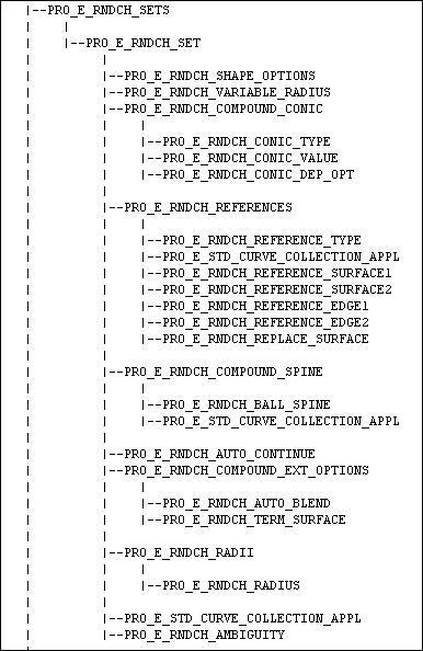
Each PRO_E_RNDCH_SET specifies a round set, which is a round piece (geometry) created as per the placement references and consists of the following
elements:
| • | PRO_E_RNDCH_SHAPE_OPTIONS—Specifies the shape options and have the following values:
|
| • | PRO_E_RNDCH_VARIABLE_RADIUS—Specifies if the round is of a constant or variable type. |
| • | PRO_E_RNDCH_COMPOUND_CONIC—Specifies if the round uses a conic section for the shape. It can be defined as:
|
| • | PRO_E_RNDCH_REFERENCES—Specifies a set of valid references of the round feature. |
| • | PRO_E_RNDCH_COMPOUND_SPINE—This is another option for defining the shape of the round. Specifies the spine and has the following elements:
Note
During the creation of rounds, the options D1 x D2 Conic and Normal to spine cannot be used together. Due to this restriction, the existing rounds with their conic type option set as PRO_ROUND_CONIC_INDEPENDENT and with the round creation method set to PRO_ROUND_NORMAL_TO_SPINE are reset to PRO_ROUND_ROLLING_BALL when the round is redefined. Therefor, for the conic type option PRO_ROUND_CONIC_INDEPENDENT you must specify the round creation method as PRO_ROUND_ROLLING_BALL.
|
| • | PRO_E_RNDCH_AUTO_CONTINUE—Specifies whether surfaces will be extended to meet the designated round radius. The valid values are:
This element is required if PRO_E_RNDCH_REFERENCE_TYPE = PRO_ROUND_REF_EDGE.
|
| • | PRO_E_RNDCH_COMPOUND_EXT_OPTIONS—Specifies the external options. This is an optional element. It has the following elements:
|
| • | PRO_E_RNDCH_RADII—Specifies the radii, as an array of radius or PRO_E_RNDCH_RADIUS and is required if PRO_E_RNDCH_SHAPE_OPTIONS is not equal to PRO_ROUND_TYPE_THROUGH_CURVE and PRO_E_RNDCH_SHAPE_OPTIONS is not equal to PRO_ROUND_TYPE_FULL. |
| • | PRO_E_STD_CURVE_COLLECTION_APPL—Specifies the curve collection and is required if PRO_E_RNDCH_SHAPE_OPTIONS is equal to PRO_ROUND_TYPE_THROUGH_CURVE. |
| • | PRO_E_RNDCH_AMBIGUITY—Specifies round set ambiguity. Note
Ambiguity occurs in round features when other placement locations exist for the round set. The ambiguity condition occurs
when two surfaces intersect in multiple locations.
|
Element Details of PRO_E_RNDCH_REFERENCES for Round
Each PRO_E_RNDCH_REFERENCES specifies a set of valid references of the round feature and has the following elements:
| • | PRO_E_RNDCH_REFERENCE_TYPE—Specifies the reference types and valid values are:
|
| • | PRO_E_STD_CURVE_COLLECTION_APPL—Specifies the reference edges of the chain collection. It is required if PRO_E_RNDCH_REFERENCE_TYPE is equal to PRO_ROUND_REF_EDGE. In Creo TOOLKIT 7.0.0.0 and later, you can select the reference edges from both different solid bodies as well as quilts. The resulting geometry
is attached back to the same solid body or quilt from where the referenced edges were selected.
|
| • | PRO_E_RNDCH_REFERENCE_SURFACE1—Specifies the first reference surface and is required if PRO_E_RNDCH_REFERENCE_TYPE is equal to PRO_ROUND_REF_SURF_SURF. |
| • | PRO_E_RNDCH_REFERENCE_SURFACE2—Specifies the second reference surface and is required if PRO_E_RNDCH_REFERENCE_TYPE is equal to PRO_ROUND_REF_SURF_SURF or PRO_E_RNDCH_REFERENCE_TYPE is equal to PRO_ROUND_REF_EDGE_SURF. |
| • | PRO_E_RNDCH_REFERENCE_EDGE1—Specifies the first reference edge and is required if PRO_E_RNDCH_REFERENCE_TYPE is equal to PRO_ROUND_REF_EDGE_SURF or PRO_E_RNDCH_REFERENCE_TYPE is equal to PRO_ROUND_REF_EDGE_EDGE and PRO_E_RNDCH_SHAPE_OPTIONS is equal to PRO_ROUND_TYPE_FULL. |
| • | PRO_E_RNDCH_REFERENCE_EDGE2—Specifies the second reference edge and is required if PRO_E_RNDCH_REFERENCE_TYPE is equal to PRO_ROUND_REF_EDGE_EDGE and PRO_E_RNDCH_SHAPE_OPTIONS is equal to PRO_ROUND_TYPE_FULL. |
| • | PRO_E_RNDCH_REPLACE_SURFACE—Specifies the surface to be replaced and is required if PRO_E_RNDCH_REFERENCE_TYPE is equal to PRO_ROUND_REF_SURF_SURF and PRO_E_RNDCH_SHAPE_OPTIONS is equal to PRO_ROUND_TYPE_FULL. |
Element Details of PRO_E_RNDCH_RADIUS for Round
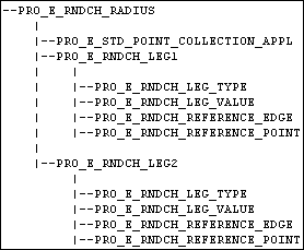
Each PRO_E_RNDCH_RADIUS has the following elements:
| • | PRO_E_STD_POINT_COLLECTION_APPL—Specifies a point, which governs the value of the radius. |
| • | PRO_E_RNDCH_LEG1—Specifies the leg1. |
| • | PRO_E_RNDCH_LEG2—Specifies the leg2 and is required if PRO_E_RNDCH_CONIC_DEP_OPT is equal to PRO_ROUND_CONIC_INDEPENDENT. |
Each PRO_E_RNDCH_LEG1 or PRO_E_RNDCH_LEG2 has the following elements:
| • | PRO_E_RNDCH_LEG_TYPE—ProRoundRadiusType specifies leg type and is a mandatory element. It is of the following types:
|
| • | PRO_E_RNDCH_LEG_VALUE—Specifies leg value and is required if PRO_E_RNDCH_LEG_TYPE is equal to PRO_ROUND_RADIUS_TYPE_VALUE. |
| • | PRO_E_RNDCH_REFERENCE_EDGE—Specifies reference edge having the value as PRO_E_EDGE and is required if PRO_E_RNDCH_LEG_TYPE is equal to PRO_ROUND_RADIUS_THROUGH_POINT. |
| • | PRO_E_RNDCH_REFERENCE_POINT—Specifies reference point having the value as PRO_E_POINT and is required if PRO_E_RNDCH_LEG_TYPE is equal to PRO_ROUND_RADIUS_THROUGH_POINT. |
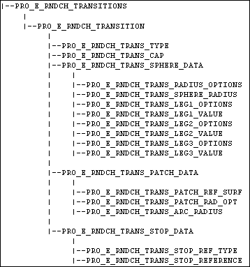
Element Details of PRO_E_RNDCH_TRANSITION for Round
Each PRO_E_RNDCH_TRANSITION represents user-defined transitions for the entire round feature and consists of the following elements:
| • | PRO_E_RNDCH_TRANS_TYPE specifies the type of the transition type. Valid values are:
|
| • | PRO_E_RNDCH_TRANS_CAP—Specifies the capping surface for round feature. It has the following values:
|
| • | PRO_E_RNDCH_TRANS_SPHERE_DATA—Specifies sphere data and consists of the following elements:
|
| • | PRO_E_RNDCH_TRANS_PATCH_DATA—Specifies the patch data and is required if PRO_E_RNDCH_TRANS_TYPE is equal to PRO_ROUND_TRANS_PATCH. It has the following elements:
|
| • | PRO_E_RNDCH_TRANS_STOP_DATA—Specifies the capping surface. It has the following elements:
|
Creating a Round
Function Introduced:
Use the function ProFeatureCreate() to create a round based on element tree input. For more information about ProFeatureCreate(), refer to the section Overview of Feature Creation in the Element Trees: Principles of Feature Creation section.
Note
In Pro/ENGINEER Wildfire 2.0,
| • | Pro/TOOLKIT does not support the temporary geometry required for user-specified ambiguity and non-default transitions. Therefore, these elements cannot be used for creation of new rounds. |
| • | If transitions are specified in the input element tree, a round feature with the default transition will be created. |
| • | In case of ambiguous situation (where more than one valid solutions exist, e.g. for surface-surface round - surfaces having discontinuous edges of intersection), a round feature with default solution will be created. |
Redefining a Round
Function Introduced:
Use the function ProFeatureRedefine() to redefine a round based on the changes made in the element tree. For more information about ProFeatureRedefine(), refer to the section Feature Redefine in the Element Trees: Principles of Feature Creation section.
Note
In Pro/ENGINEER Wildfire 2.0,
| • | A round feature having default transition, can not be redefined to have any transition. |
| • | A round feature having a Pro/ENGINEER user interface defined transition can be redefined to other type of transition, for example, from intersect type to spherical type. The input element tree must have a valid transition of the required type. |
Accessing a Round
Function Introduced:
Use the function ProFeatureElemtreeExtract() to create a feature element tree that describes the contents of a round and to retrieve the element tree description of a
round. For more information about ProFeatureElemtreeExtract(), refer to the section Feature Inquiry in the Element Trees: Principles of Feature Creation section.
