Mechanism Design: Mechanism Features
This section describes the programmatic creation of mechanism modeling entities such as springs and dampers as Creo Parametric features.
The section also explains for to add motor features such as, servo motors, forces motors, and so on.
We recommend you read the section, Overview of Feature Creation in the section, Element Trees: Principles of Feature Creation. It provides the necessary background for creating features using Creo TOOLKIT.
Mechanism Spring Feature
A spring generates a translational or rotational spring force in a mechanism. It produces a linear spring force when stretched or compressed, and a torsion force when rotated. The magnitude of the spring force is directly proportional to the amount of displacement from the position of equilibrium.
Springs are created as Creo Parametric features and their values are stored as valid Creo Parametric parameters.
Feature Element Tree for the Mechanism Spring Feature
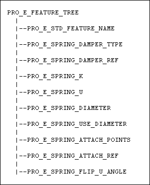
The element tree for the Mechanism Spring feature is documented in the header file, ProDamperFeat.h. The following figure demonstrates the structure of the feature element tree.
Feature Element Tree for Mechanism Spring
Image
The following list details special information about the elements in the feature element tree:
•  PRO_E_STD_FEAT_NAME—Specifies the name of the mechanism spring feature.
•  PRO_E_SPRING_DAMPER_TYPE—Specifies the mechanism spring feature type. It can have the following values:
  PRO_SPRING_DAMPER_FORCE—Specifies an extension or compression spring.
  PRO_SPRING_DAMPER_TORQUE—Specifies a torsion spring.
•  PRO_E_SPRING_DAMPER_REF—Specifies the spring placement references. For an extension spring or compression spring, you can select the translational axis or two points on two different bodies as the placement references. For a torsion spring, you can select the rotational axis as the placement reference.
•  PRO_E_SPRING_K—Specifies the value for the stiffness coefficient of the spring.
•  PRO_E_SPRING_U—Specifies the value for the unstretched length of the spring.
•  PRO_E_SPRING_DIAMETER—Specifies the value for the spring icon diameter for an extension spring.
•  PRO_E_SPRING_USE_DIAMETER—Specifies the Adjust Icon Diameter option (available in the Creo Parametric user interface) that allows you to change the value of the spring icon diameter. This element is not available by default. It takes the following values:
  PRO_SPRING_USE_DIAMETER_NO
  PRO_SPRING_USE_DIAMETER_YES
•  PRO_E_SPRING_ATTACH_POINTS—Specifies the attachment points for the two ends of a torsion spring. The attachment points can be of the following types:
  PRO_SPRING_USE_MOTION_AXIS_ZERO—Specifies the JAS (Joint Axis Set) option, where the attachment references are automatically populated with the selected JAS references.
  PRO_SPRING_CUSTOM_ATTACHMENT_POINTS—Specifies custom attachment references where you can specify two attachment references such as datum planes, datum points, and vertices. The vector between each attachment reference and the selected rotational axis is automatically calculated. By default, the greatest angle between the two vectors is defined as the spring angle. On selecting both the attachment references, the unstretched value of the torsion spring is automatically updated according to the current angle between the two vectors.
•  PRO_E_SPRING_ATTACH_REF—Specifies the actual attachment references for the torsion spring depending upon the attachment type set for the element PRO_E_SPRING_ATTACH_POINTS.
•  PRO_E_SPRING_FLIP_U_ANGLE—Specifies the option to flip the direction of the current angle between the attachment references for a torsion spring.
Mechanism Damper Feature
A damper generates a force that removes energy from a moving mechanism and dampens its motion. The damper force is always proportional to the magnitude of velocity of the entity on which you are applying the damper, and acts in the direction opposite to movement.
Dampers are created as Creo Parametric features and their values are stored as valid Creo Parametric parameters.
Feature Element Tree for the Mechanism Damper Feature
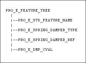
The element tree for the Mechanism Damper feature is documented in the header file, ProDamperFeat.h. The following figure demonstrates the structure of the feature element tree.
Feature Element Tree for Mechanism Damper
Image
The following list details special information about the elements in the feature element tree:
•  PRO_E_STD_FEAT_NAME—Specifies the name of the mechanism damper feature.
•  PRO_E_SPRING_DAMPER_TYPE—Specifies the mechanism damper feature type. It can have the following values:
  PRO_SPRING_DAMPER_FORCE—Specifies an extension damper or compression damper.
  PRO_SPRING_DAMPER_TORQUE—Specifies a torsion damper.
•  PRO_E_SPRING_DAMPER_REF—Specifies the damper placement references. For an extension damper or compression damper, you can select the translational or slot axis, or two points on two different bodies as the placement references. For a torsion damper, you can select the rotational axis as the placement reference.
•  PRO_E_DMP_CVAL—Specifies the value for the damping coefficient.
Mechanism Belt Feature
A belt is treated as a connection connecting all the pulley bodies. The belt provides the same angular velocity to all pulleys connected by it.
Belts are created as Creo Parametric features and their values are stored as valid Creo Parametric parameters.
Feature Element Tree for the Mechanism Belt Feature
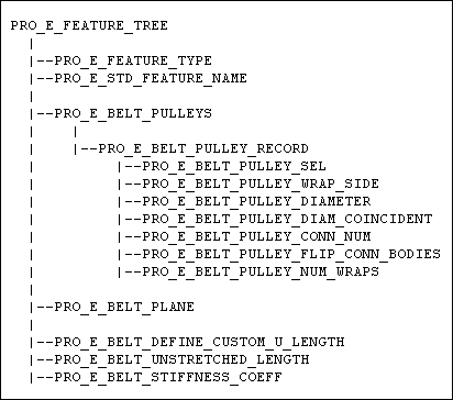
The element tree for the Mechanism Belt feature is documented in the header file, ProBeltFeat.h. The following figure demonstrates the structure of the feature element tree.
Feature Element Tree for Mechanism Belt
Image
The following list details special information about the elements in the feature element tree:
•  PRO_E_FEATURE_TYPE—Specifies the feature type.
•  PRO_E_STD_FEATURE_NAME—Specifies the name of the mechanism belt feature.
•  PRO_E_BELT_PULLEYS—Specifies an array of pulley bodies of the type PRO_E_BELT_PULLEY_RECORD which consists of the following elements:
  PRO_E_BELT_PULLEY_SEL—Specifies the geometric reference selected as the pulley body. It can be a cylindrical surface, a circular curve or edge, or a PIN or Cylinder connection. You must define at least two pulley bodies for the belt.
Creo Parametric automatically selects both the sides of the cylindrical surface or the circular curve or edge so that the pulley is complete. In case of a cylindrical or circular reference, the pulley’s axis of rotation is automatically detected by detecting a PIN or Cylinder connection aligned to the theoretical axis of the geometric reference and perpendicular to the belt plane. If such as a connection does not exist, the reference is considered invalid. In case of a connection reference, the rotation axis of the selected connection is used as the pulley axis.
  PRO_E_BELT_PULLEY_WRAP_SIDE—Specifies the pulley wrapping direction. It can be left (-1) or right (+1) and relative to the previous pulley. You can flip the belt to the other contact point detected between the belt and the pulley.
  PRO_E_BELT_PULLEY_DIAMETER—Specifies the pulley diameter. A cylindrical curve with the specified diameter is displayed around the selected pulley reference and on the belt plane. The pulley diameter is coincident with the pulley reference by default, except in case of connection references.
  PRO_E_BELT_PULLEY_DIAM_COINCIDENT—Indicates if the pulley diameter is coincident with the pulley reference. This element is set to PRO_B_TRUE, which means the pulley diameter is set to the value Coincident by default for non-connection references.
  PRO_E_BELT_PULLEY_CONN_NUM—Specifies the number of the PIN or Cylinder connection selected as the pulley reference from the available valid connections. One of the bodies that defines the connection is considered the pulley body, while the other body connected to it is considered the carrier body.
  PRO_E_BELT_PULLEY_FLIP_CONN_BODIES—Specifies the option to flip between the pulley and carrier bodies, in case of connection references. This option is not available in case of geometric references.
  PRO_E_BELT_PULLEY_NUM_WRAPS—Specifies the number of full wraps around the currently selected pulley. The wraps are considered as not overlapping and are not displayed in the 3D icon for the belt. The number of wraps affects the belt length. In case of open ended belts, the number of wraps influences the motion extent of the connected bodies.
•  PRO_E_BELT_PLANE—Specifies the planar surface or datum plane that defines the belt plane. The plane should be perpendicular to the rotation axis of the first pulley. This element is optional. If the belt plane is not specified, it is detected based on the selected pulley references as follows:
  Cylindrical surfaces—If a cylindrical surface is used as the pulley reference, the perpendicular plane positioned in the center of the cylindrical surface (for the first pulley in case of multiple pulleys) is used as the belt plane
  Circular edge or curve—If a circular edge or curve is used as the pulley reference, the plane for the corresponding edge or curve (for the first pulley in case of multiple pulleys) is used as the belt plane.
  PIN/Cylinder connections—In case of connection references, the internal orange body zero point (for the first pulley in case of multiple pulleys) is used as the belt plane.
•  PRO_E_BELT_DEFINE_CUSTOM_U_LENGTH—Identifies if the unstretched belt length can be specified by the user, or if it is system-defined. The length is system-defined by default.
•  PRO_E_BELT_UNSTRETCHED_LENGTH—Specifies the value for the unstretched belt length. The system-defined length is calculated based on the pulley references and their specified diameters. When the user enters a desired belt length, Creo Parametric tries to reconnect the assembly according to the specified belt length. If the reconnect operation fails, the belt length reverts to the previously entered value.
•  PRO_E_BELT_STIFFNESS_COEFF—Specifies the belt stiffness coefficient value.
Mechanism 3D Contact Feature
3D contacts are connections between a group of surfaces selected from two parts. These connections are similar to cams, joints, gears, and belts. Depending on the surfaces selected, 3D contacts can be of the following types:
•  Sphere to Sphere (point contact)
•  Sphere to Planar surface (point contact)
•  Cylinder to Cylinder (line contact)
•  Cylinder to Planar surface (line contact)
•  Sphere to Cylinder (point contact)
•  Toroid to Plane (point contact)
3D Contacts are created as Creo Parametric features and their values are stored as Creo Parametric feature parameters.
Feature Element Tree for the Mechanism 3D Contact Feature
The element tree for the Mechanism 3D Contact feature is documented in the header file, ProContact3dFeat.h. The following figure demonstrates the structure of the feature element tree.
Feature Element Tree for Mechanism 3D Contact
Image
Note
From Pro/ENGINEER Wildfire 5.0 onwards, the feature element tree for the 3D Contact feature has been updated. 3D Contact features created using the old tree are represented in the new tree format. You will need to rebuild your existing Pro/TOOLKIT applications according to the new element tree.
The following list details special information about the elements in the feature element tree:
•  PRO_E_FEATURE_TYPE—Specifies the feature type.
•  PRO_E_STD_FEATURE_NAME—Specifies the name of the mechanism 3D contact feature.
•  PRO_E_C3D_MAT_OPTION1—Specifies the material type for the first contact part. The material type is given by the enumerated type ProC3dMaterialType that takes the following values:
  PRO_C3D_MAT_DEFAULT—Specifies the material properties of the participating contact part. This is the default type. If this type is set, the elements PRO_E_C3D_POISSON1, PRO_E_C3D_YOUNG1, and PRO_E_C3D_DAMPING1 are not available for modification and are set by default.
  PRO_C3D_MAT_SEL_MAT—Allows you to select a material type from the list of materials used in the assembly or from the material library directory. If this type is set, the elements PRO_E_C3D_POISSON1, PRO_E_C3D_YOUNG1, and PRO_E_C3D_DAMPING1 are not available for modification and are set as per the selected material.
  PRO_C3D_MAT_USE_VALS—Allows you to specify the values for the material properties. The elements PRO_E_C3D_POISSON1, PRO_E_C3D_YOUNG1, and PRO_E_C3D_DAMPING1 are available and can be set as required.
•  PRO_E_C3D_REF1_RECS—Specifies an array of selected surface references belonging to the first part that is used in the 3D contact. You can select multiple surfaces having a common center, equal diameter and a common edge. The surface reference is of type PRO_E_C3D_REF_REC and consists of the following elements:
  PRO_E_C3D_REF—Specifies the selected surface reference. The reference can be a spherical, cylindrical, toroidal, or planar surface, or a vertex. If you select a vertex from the first part as one of the references, a sphere is displayed around the vertex and the vertex is considered as a sphere in the 3D contact. If the first reference is a vertex, specify the value for the vertex radius using the element PRO_E_C3D_VERT_RAD. The first surface determines the second part that can be selected for the connection.
  PRO_E_C3D_REF_FULL_GEOM—Specifies whether a complete surface or a segment of the surface is selected. This option is specified by the enumerated type ProC3dFullGeomFlag and has the following values:
  PRO_C3D_FULL_GEOM—Specifies that a complete surface has been selected for the 3D contact.
  PRO_C3D_PARTIAL_GEOM—Specifies that a segment of a cylinder, sphere, or toroid has been selected for the 3D contact.
  PRO_E_C3D_REF_FLIP—Specifies if the direction for the 3D contact is flipped. The value for this element is PRO_B_FALSE by default which means the contact direction is not flipped and the surface direction is used. This element is applicable only if you use quilt surfaces to create the 3D contacts.
•  PRO_E_C3D_MAT_NAME1—Specifies the name of the material type selected for the first contact part. This element can be set only if the element PRO_E_C3D_MAT_OPTION1 is set to PRO_C3D_MAT_SEL_MAT.
•  PRO_E_C3D_POISSON1—Specifies the value for Poisson’s ratio for the first contact part.
•  PRO_E_C3D_YOUNG1—Specifies the value for Young’s modulus for the first contact part.
•  PRO_E_C3D_DAMPING1—Specifies the value for the damping coefficient for the first contact part.
•  PRO_E_C3D_MAT_OPTION2—Specifies the material type for the second contact part. Refer to the description of the element PRO_E_C3D_MAT_OPTION1 for the material types that you can select.
•  PRO_E_C3D_REF2_RECS—Specifies an array of selected surface references of the type PRO_E_C3D_REF_REC from the second part that is used in the 3D contact. Refer to the description of the element PRO_E_C3D_REF1_RECS for information on the options that can be set for each surface reference. If you select a vertex from the second part as one of the references, a sphere is displayed around the vertex and the vertex is considered as a sphere in the 3D contact. If the second reference is a vertex, the PRO_E_C3D_VERT_RAD element becomes available for you to specify the value for the vertex radius.
•  PRO_E_C3D_MAT_NAME2—Specifies the name of the material type selected for the second contact part. This element can be set only if the element PRO_E_C3D_MAT_OPTION2 is set to PRO_C3D_MAT_SEL_MAT.
•  PRO_E_C3D_POISSON2—Specifies the value for Poisson’s ratio for the second contact part.
•  PRO_E_C3D_YOUNG2—Specifies the value for Young’s modulus for the second contact part.
•  PRO_E_C3D_DAMPING2—Specifies the value for the damping coefficient for the second contact part.
•  PRO_E_C3D_VERT_RAD—Specifies the value for the vertex radius if a vertex is selected as one the references.
•  PRO_E_C3D_FRICTION—Identifies if friction will be used in the contact calculation. This element is set to PRO_B_FALSE by default which means no friction.
•  PRO_E_C3D_STATIC_FRIC_COEF—Specifies the value for the static friction coefficient.
•  PRO_E_C3D_KINEM_FRIC_COEF—Specifies the value for the kinematic friction coefficient.
Mechanism Motor Features
The Mechanism Motor element tree enables you to add servo and force motors.
Use servo motors to impose a particular motion on a mechanism. Servo motors cause a specific type of motion to occur between two bodies in a single degree of freedom. Add servo motors to your model to prepare it for analysis.
Use force motors to impose a particular load on a mechanism. A force motor causes motion by applying a force in a single degree of freedom along a translational, rotational, or slot axis.
Feature Element Tree for the Mechanism Motor Feature
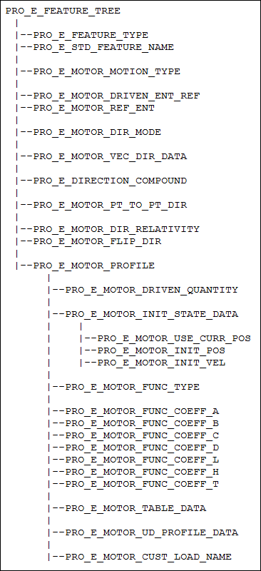
The element tree for the Mechanism Motor feature is documented in the header file, ProMotorFeat.h. The following figure demonstrates the structure of the feature element tree.
Feature Element Tree for Mechanism Motor
Image
The following table describes the elements in the element tree for the Mechanism Motor feature:
Element ID
Data Type
Description
PRO_E_FEATURE_TYPE
PRO_VALUE_TYPE_INT
Specifies the type of the motor feature.
PRO_E_STD_FEATURE_NAME
PRO_VALUE_TYPE_WSTRING
Specifies the name of the mechanism motor feature.
PRO_E_MOTOR_MOTION_TYPE
PRO_VALUE_TYPE_INT
Specifies the motion type of motor. The motion type is specified using the enumerated data type ProMotorMotionType. The valid values are:
•  PRO_MOTOR_TRANSLATIONAL
•  PRO_MOTOR_ROTATIONAL
•  PRO_MOTOR_SLOT
PRO_E_MOTOR_DRIVEN_ENT_REF
PRO_VALUE_TYPE_SELECTION
Specifies the reference geometry for driven entity. You can select a axes of motion or geometry such as point or plane.
Note
When you select references that are a point or a plane to define the servo motor, you are creating a geometric servo motor.
PRO_E_MOTOR_ENT_REF
PRO_VALUE_TYPE_SELECTION
Specifies the reference geometry for a geometric servo motor. You can select a point or plane.
PRO_E_MOTOR_DIR_MODE
PRO_VALUE_TYPE_INT
Specifies the type of motion direction for motors. The valid values are defined in enumerated data type ProMotorFMDirMode:
•  PRO_MOTOR_FM_VEC_DIR—The direction is defined by explicit vector in a coordinate system.
•  PRO_MOTOR_FM_STD_DIR—The direction is defined by standard direction reference such as, straight edge, curve, axis, and plane normal.
•  PRO_MOTOR_FM_P2P_DIR—The direction is defined by a pair of point or vertex.
PRO_E_MOTOR_VEC_DIR_DATA
PRO_VALUE_TYPE_POINTER
This element is applicable only for geometric force motors.
Specifies a compound element which defines the options to set the direction using explicit vector.
PRO_E_MOTOR_VEC_DIR_CSYS
PRO_VALUE_TYPE_SELECTION
Specifies the reference frame for the vector. If the reference frame is not specified, then the World Coordinate System is used.
PRO_E_MOTOR_VEC_DIR_X
PRO_E_MOTOR_VEC_DIR_Y
PRO_E_MOTOR_VEC_DIR_Z
PRO_VALUE_TYPE_DOUBLE
Specifies the value for X, Y, and Z vectors.
PRO_E_DIRECTION_COMPOUND
PRO_VALUE_TYPE_POINTER
This element is applicable for geometric servo and force motors.
Specifies a compound element which defines the options to set the direction using standard direction reference.
PRO_E_DIRECTION_REFERENCE
PRO_VALUE_TYPE_SELECT
Specifies a motion reference.
PRO_E_DIRECTION_FLIP
PRO_VALUE_TYPE_INT
Flips to reverse the direction of the force or the torque.
PRO_E_MOTOR_PT_TO_PT_DIR
PRO_VALUE_TYPE_SELECT
This element is applicable only for geometric force motors. Specifies the selection of a pair of points to set the direction for point-to-point direction.
PRO_E_MOTOR_DIR_RELATIVITY
PRO_VALUE_TYPE_INT
This element is applicable only for geometric force motors. Specifies the direction of motion relative to ground or driven body.
PRO_E_MOTOR_FLIP_DIR
PRO_VALUE_TYPE_INT
Flips to reverse the direction of the motion.
Note
It defines the direction when connection axis motors or geometric motors do no use the element PRO_E_DIRECTION_COMPOUND to define the direction.
PRO_E_MOTOR_PROFILE
PRO_VALUE_TYPE_POINTER
Specifies a compound element that defines the profile options for a motor.
PRO_E_MOTOR_DRIVEN_QUANTITY
PRO_VALUE_TYPE_INT
Specifies the type of driven quantity. The valid values are defined in the enumerated data type ProMotorDrivenQuantity:
•  PRO_MOTOR_POSITION—Specifies the motion of servo motor in terms of the position of the selected entity.
•  PRO_MOTOR_VELOCITY—Specifies the motion of servo motor in terms of its velocity.
•  PRO_MOTOR_ACCELERATION—Specifies the motion of servo motor in terms of its acceleration.
•  PRO_MOTOR_FORCE—Specifies a force motor.
PRO_E_MOTOR_INIT_STATE_DATA
PRO_VALUE_TYPE_POINTER
Specifies a compound element that defines the options for initial position of servo motor for PRO_MOTOR_VELOCITY and PRO_MOTOR_ACCELERATION type of motion.
PRO_E_MOTOR_USE_CURR_POS
PRO_VALUE_TYPE_INT
Specifies that the current position of the servo motor is used as the initial starting position.
PRO_E_MOTOR_INIT_POS
PRO_VALUE_TYPE_DOUBLE
This element is applicable only when PRO_E_MOTOR_USE_CURR_POS is set to No.
Specifies a starting position for the servo motor.
PRO_E_MOTOR_INIT_VEL
PRO_VALUE_TYPE_DOUBLE
This element is applicable only for PRO_MOTOR_ACCELERATION type of motion.
Specifies the initial velocity of the driven entity.
PRO_E_MOTOR_FUNC_TYPE
PRO_VALUE_TYPE_INT
Specifies the type of motion for the motor using the enumerated data type ProMotorFuncType. The valid values are:
•  PRO_MOTOR_CONSTANT—Creates a constant profile.
•  PRO_MOTOR_RAMP—Creates a profile that changes linearly over time.
•  PRO_MOTOR_COSINE—Assigns a cosine wave value to the motor profile.
•  PRO_MOTOR_SCCA—Simulates a cam profile output. This option is available for acceleration motors only.
•  PRO_MOTOR_CYCLOIDAL—Simulates a cam profile output.
•  PRO_MOTOR_PARABOLIC—Simulates a trajectory for a motor.
•  PRO_MOTOR_POLYNOMIAL—Defines third degree polynomial motor profiles.
•  PRO_MOTOR_TABLE—Generates the motor motion with values from a four-column table. You can use a table of output measure results.
•  PRO_MOTOR_USER_DEFINED—Specifies any kind of complex profile defined by multiple expression segments.
•  PRO_MOTOR_CUSTOM_LOAD—Applies a complex, externally-defined set of loads to your model. This option is only available for the force motor definition.
PRO_E_MOTOR_FUNC_COEFF_A
PRO_E_MOTOR_FUNC_COEFF_B
PRO_E_MOTOR_FUNC_COEFF_C
PRO_E_MOTOR_FUNC_COEFF_D
PRO_E_MOTOR_FUNC_COEFF_L
PRO_E_MOTOR_FUNC_COEFF_H
PRO_E_MOTOR_FUNC_COEFF_T
PRO_VALUE_TYPE_DOUBLE
Specifies the values for the function coefficients.
PRO_E_MOTOR_TABLE_DATA
PRO_VALUE_TYPE_POINTER
Specifies a compound element that defines all the options for table motor type.
PRO_E_MOTOR_TBL_INTERPOL_TYPE
PRO_VALUE_TYPE_INT
Specifies the interpolation method using the enumerated data type ProMotorTableInterpType. The valid values are:
•  PRO_MOTOR_TBL_LINEAR—Connects the table points with a straight line.
•  PRO_MOTOR_TBL_SPLINE—Fits a cubic spline to each set of points.
•  PRO_MOTOR_TBL_MONOTONIC—Produces a monotonic trajectory when you use default velocity values and monotonic magnitude values.
PRO_E_MOTOR_TBL_ROWS
PRO_VALUE_TYPE_POINTER
Specifies an array of table rows.
PRO_E_MOTOR_TBL_ROW
PRO_VALUE_TYPE_POINTER
Specifies a compound element that defines the options for each table row.
PRO_E_MOTOR_TBL_VAR_VAL
PRO_VALUE_TYPE_DOUBLE
Specifies the value for independent variables in the first column of the table.
PRO_E_MOTOR_TBL_FUNC_VAL
PRO_VALUE_TYPE_DOUBLE
Specifies the value for driven quantity variables in the second column of the table.
PRO_E_MOTOR_TBL_DERIV_GIVEN
PRO_VALUE_TYPE_INT
This element is applicable only if interpolation type is set to PRO_MOTOR_TBL_MONOTONIC.
A flag which checks if derivative value has been specified by the user.
PRO_E_MOTOR_TBL_DERIV_VAL
PRO_VALUE_TYPE_DOUBLE
This element is applicable only if interpolation type is set to PRO_MOTOR_TBL_MONOTONIC.
Specifies the value for function derivative in a table row.
PRO_E_MOTOR_TBL_DEPEND_ON_FILE
PRO_VALUE_TYPE_INT
A flag which checks if the table values are dependent on an external file.
PRO_E_MOTOR_TBL_FILE_NAME
PRO_VALUE_TYPE_WSTRING
Specifies the name of the table.
PRO_E_MOTOR_UD_PROFILE_DATA
PRO_VALUE_TYPE_POINTER
Specifies a compound element that defines all the options for user-defined motor type.
PRO_E_MOTOR_UD_EXPR_ARR
PRO_VALUE_TYPE_POINTER
Specifies an array that defines the options for user-defined expressions.
PRO_E_MOTOR_UD_EXPR_DATA
PRO_VALUE_TYPE_POINTER
Specifies a compound that defines the options for each user-defined expression.
PRO_E_MOTOR_UD_EXPR
PRO_VALUE_TYPE_WSTRING
Specifies a user-defined expression.
PRO_E_MOTOR_UD_DOM_TYPE
PRO_VALUE_TYPE_INT
Specifies the type of domain for the expression using the enumerated data type ProMotorUDExprDomainType.
PRO_E_MOTOR_UD_DOM_LOWER_BOUND
PRO_VALUE_TYPE_DOUBLE
Specifies the value for lower bound.
PRO_E_MOTOR_UD_DOM_UPPER_BOUND
PRO_VALUE_TYPE_DOUBLE
Specifies the value for upper bound.
PRO_E_MOTOR_CUST_LOAD_NAME
PRO_VALUE_TYPE_WSTRING
This element is applicable only for force motors when the element PRO_E_MOTOR_FUNC_TYPE is set to PRO_MOTOR_CUSTOM_LOAD.
Specifies the name of the custom file that has pre-defined custom loads.