Element Trees: Draft Features
This section introduces and shows how to create, redefine and access draft features.
Draft Feature
The Draft feature adds a draft angle between -89.9? and +89.9? to individual surfaces or to a series of surfaces.
You can draft either solid surfaces or quilt surfaces, but not a combination of both. The first selected surface determines the type of additional surfaces (solid or quilts) that can be selected as draft surfaces for this feature.
Some of the terms associated with the Draft feature are:
•  Draft surfaces—The surfaces of the model to be drafted.
•  Draft hinges—Lines and curves on the draft surfaces that the surfaces are pivoted about (also called neutral curves), or quilt of surfaces. Draft hinges can be defined by:
  A plane, in which case the draft surfaces are pivoted about their intersection with the plane.
  Individual curve chains on the draft surfaces.
  A quilt, in which case the draft surfaces are pivoted about their intersection with the quilt.
•  Draft direction—Direction used to measure the draft angle and can be defined in terms of:
  A plane, in which case the draft direction is normal to this plane.
  A straight edge or a datum axis, in which case the draft direction is parallel to the edge or axis.
  Two points, such as datum points or model vertices, in which case the draft direction is parallel to the line connecting the two points.
  A coordinate system, in which case the draft direction initially defaults to the direction of its x-axis.
•  Draft angle—The angle between the draft direction and the resulting drafted surfaces. If the draft surfaces are split, you can define two independent angles for each side of the drafted surface. Draft angles must be within the range of -89.9? and +89.9?.
Feature Element Tree for the Draft Feature
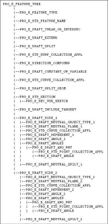
The element tree for a draft feature is documented in the header file ProDraft.h, and has a simple structure. The following figure demonstrates the feature element tree structure:
Feature Element tree for Draft Features
Image
The feature element tree contains no non-standard element types. The following list details special information about some of the elements in this tree:
•  PRO_E_FEATURE_TYPE—Specifies the feature type.
•  PRO_E_STD_FEATURE_NAME—Specifies the name of the feature.
•  PRO_E_DRAFT_TWEAK_OR_INTERSEC—Specifies tweak or intersect depending on whether the resulting draft surface encounters an edge of the model or not suggesting the presence of the extend option. It can have any of the following values:
  PRO_DRAFT_UI_TWEAK for creating regular draft geometry.
  PRO_DRAFT_UI_INTERSECT for adjusting the draft geometry to intersect an existing edge of the model.
  PRO_DRAFT_UI_INTERSECT_EXTEND specifies intersect with extend, when the draft does not extend to the adjacent model surface.
Note
It is an option for the earlier versions of Pro/ENGINEER.
•  PRO_E_DRAFT_EXTEND—Specifies extend option of the draft. It is of the following types:
  PRO_DRAFT_UI_NO_EXTEND—Intersect without Extend.
  PRO_DRAFT_UI_EXTEND—Intersect with Extend.
Note
It is applicable for features created using Pro/ENGINEER version prior to Pro/ENGINEER Wildfire2.0 Release and is available only when PRO_E_DRAFT_TWEAK_OR_INTERSEC is equal to PRO_DRAFT_UI_INTERSECT.
•  PRO_E_DRAFT_SPLIT—Specifies split details of the draft. It can be any of the following types:
  PRO_DRAFT_UI_SPLIT_NONE
  PRO_DRAFT_UI_SPLIT_NEUT specifies split on draft hinge.
  PRO_DRAFT_UI_SPLIT_SURF specifies split at surface.
  PRO_DRAFT_UI_SPLIT_SCTCH specifies split at sketch.
Note
Draft surfaces can be split either by the draft hinge or by a different curve on the draft surface, such as an intersection with a quilt, or a sketched curve. If you are splitting by a sketch that does not lie on the draft surface, Creo Parametric projects it on the draft surface in the direction normal to the sketching plane.
•  PRO_E_STD_SURF_COLLECTION_APPL—Specifies drafted surfaces.
•  PRO_E_DIRECTION_COMPOUND—Specifies the direction utility for the draft.
•  PRO_E_DRAFT_CONSTANT_OR_VARIABLE—Specifies constant or variable draft. For variable draft one can specify more than one angle per draft side. It can be one of the following types:
  PRO_DRAFT_UI_VARIABLE
  PRO_DRAFT_UI_CONSTANT
•  PRO_E_STD_CURVE_COLLECTION_APPL—Specifies the exclude loop or the draft hinges.
•  PRO_E_DRAFT_SPLIT_GEOM—Specifies split geometry (sketch, plane, or quilt used for splitting) and is an optional element.
•  PRO_E_STD_SECTION—Specifies the split geometry and is an optional element. It contains the following element:
  PRO_E_SEC_USE_SKETCH—Specifies the selected split geometry and is an optional element.
•  PRO_E_DRAFT_INCLUDE_TANGENT—Specifies included tangent. It can be any of the following types:
  PRO_DRAFT_UI_NOT_INC_TANG specifies the non-included tangents.
  PRO_DRAFT_UI_INC_TANG specifies the included tangents.
•  PRO_E_DRAFT_SIDE_1—Specifies details about first draft’s side.
•  PRO_E_DRAFT_SIDE_2—Specifies details about second draft’s side.
Element Details of PRO_E_DRAFT_SIDE_1
Each PRO_E_DRAFT_SIDE_1 has the following elements:
•  PRO_E_DRAFT_NEUTRAL_OBJECT_TYPE_1—Specifies the type of draft hinge. It can be any of the following types:
  PRO_DRAFT_UI_NO_NEUT—Specifies that no draft hinge have been fixed.
  PRO_DRAFT_UI_PLANE—Specifies a plane. In this case, the draft surfaces are pivoted about their intersection with this plane.
  PRO_DRAFT_UI_CURVE—Specifies a curve chain located on the draft surfaces.
  PRO_DRAFT_UI_QUILT—Specifies a quilt of surfaces. In this case, the draft surfaces are pivoted about their intersection with the quilt.
  PRO_DRAFT_UI_RND_HINGE—Specifies a round surface that must be adjacent to the draft surface.
•  PRO_E_DRAFT_NEUTRAL_PLANE_1—Specifies the plane selected as the draft hinge.
•  PRO_E_STD_CURVE_COLLECTION_APPL—Specifies exclude loop or draft hinges.
•  PRO_E_DRAFT_DEPENDENT_1—Specifies the dependence and controls whether the corresponding sides are drafted and depends on the type of the draft hinge. It can be any of the following types:
  PRO_DRAFT_UI_INDEPENDENT specifies that two independent draft angles for each side of the drafted surface.
  PRO_DRAFT_UI_DEPENDENT specifies a single draft angle, with the second side drafted in the opposite direction.
  PRO_DRAFT_UI_NONE specifies that none of the sides be drafted.
•  PRO_E_DRAFT_ANGLE_1—Specifies the draft angle and is a constant value.
•  PRO_E_DRAFT_ANGLES—This is an option for a variable draft. It specifies a collection of draft angles and points PRO_E_DRAFT_ANG_PNT. Each PRO_E_DRAFT_ANG_PNT consists of the following elements:
  PRO_E_STD_POINT_COLLECTION_APPL—Specifies the point collection for the angle.
  PRO_E_DRAFT_ANGLE—Specifies the draft angle.
•  PRO_E_DRAFT_NEUTRAL_QUILT_1—Specifies the quilt of surfaces selected as the draft hinge.
Element Details of PRO_E_DRAFT_SIDE_2
Each PRO_E_DRAFT_SIDE_2 has the following elements:
•  PRO_E_DRAFT_NEUTRAL_OBJECT_TYPE_2—Specifies the type of draft hinge. It can be any of the following types:
  PRO_DRAFT_UI_NO_NEUT—Specifies that no draft hinge has been fixed.
  PRO_DRAFT_UI_PLANE—Specifies a plane. In this case, the draft surfaces are pivoted about their intersection with this plane.
  PRO_DRAFT_UI_CURVE—Specifies a curve chain located on the draft surfaces.
  PRO_DRAFT_UI_QUILT—Specifies a quilt of surfaces. In this case, the draft surfaces are pivoted about their intersection with the quilt.
•  PRO_E_DRAFT_NEUTRAL_PLANE_2—Specifies the plane selected as the draft hinge.
•  PRO_E_STD_CURVE_COLLECTION_APPL—Specifies exclude loop or draft hinges.
•  PRO_E_DRAFT_DEPENDENT_2—Specifies the dependence and controls whether the corresponding sides are drafted and depends on the type of the draft hinge. It can be any of the following types:
  PRO_DRAFT_UI_INDEPENDENT specifies that two independent draft angles for each side of the drafted surface.
  PRO_DRAFT_UI_DEPENDENT specifies a single draft angle, with the second side drafted in the opposite direction.
  PRO_DRAFT_UI_NONE specifies that none of the side be drafted.
•  PRO_E_DRAFT_ANGLE_2—Specifies the draft angle and is a constant value.
•  PRO_E_DRAFT_ANGLES—This is an option for a variable draft. It specifies a collection of draft angles and points PRO_E_DRAFT_ANG_PNT. Each PRO_E_DRAFT_ANG_PNT consists of the following elements:
  PRO_E_STD_POINT_COLLECTION_APPL—Specifies the point collection for the angle.
  PRO_E_DRAFT_ANGLE—Specifies the draft angle.
•  PRO_E_DRAFT_NEUTRAL_QUILT_2—Specifies the quilt of surfaces selected as the draft hinge.
Creating a Draft
Function Introduced:
Use the function ProFeatureCreate() to create a Draft based on element tree input. For more information about ProFeatureCreate(), refer to the section Overview of Feature Creation of Element Trees: Principles of Feature Creation.
Redefining a Draft
Function Introduced:
Use the function ProFeatureRedefine() to redefine a Draft based on the changes made in the element tree. For more information about ProFeatureRedefine(), refer to the section Feature Redefine of Element Trees: Principles of Feature Creation.
Accessing a Draft
Function Introduced:
Use the function ProFeatureElemtreeExtract() to create a feature element tree that describes the contents of a Draft and to retrieve the element tree description of a Draft. For more information about ProFeatureElemtreeExtract() refer to the section Feature Inquiry of Element Trees: Principles of Feature Creation.
Example 1: Creation of a Draft Feature
The sample code in the file UgSimpleDraftCreate.c located at <creo_toolkit_loadpoint>/protk_appls/pt_userguide/ptu_featcreat shows how to create a Simple Draft feature.
The user is prompted to select:
1. The surface to be drafted
2. The hinge (edge / curve)
3. The direction of the draft (axis, edge)
Example 2: Creation of a Draft Feature using interactive collection
The sample code in the file UgIntcollectionDraftCreate.c located at <creo_toolkit_loadpoint>/protk_appls/pt_userguide/ptu_featcreat shows how to create a draft feature using interactive collection.
The user is prompted to create a collection of:
1. The surface to be drafted ( "ProSurfacesCollect" )
2. The direction of the draft ( axis, edge - "ProSelect" )
3. The hinge ( edge / curve - "ProCurvesCollect" )
Example 3: Creation of a Draft Feature based on the Object-Action paradigm
The sample code in the file UgOADraftCreate.c located at <creo_toolkit_loadpoint>/protk_appls/pt_userguide/ptu_featcreat demonstrates creation of a simple Draft feature based on the Object-Action paradigm using selection buffer access. The user is expected to populate the selection buffer in Creo Parametric user interface with
1. A surface collection for the surfaces to be drafted
2. A curve collection for the hinge ( edge / curve )
3. A selection for the direction of the draft ( axis, edge )
This example parses the selection buffer and uses the information for the programmatic creation of draft feature. The selection buffer may be populated with the above three entries in any order. The success of feature creation depends upon the appropriateness of the data in the selection buffer.
Variable Pull Direction Draft Feature
The Variable Pull Direction Draft (VPDD) feature differs from the regular Draft feature where the pull direction is restricted to be constant. A VPDD is defined by an edge or curve, a surface that specifies the variable pull direction, a depth option, and optionally, splitting surfaces.
Feature Element Tree for the Variable Pull Direction Draft Feature
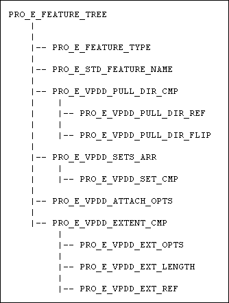
The element tree for the Variable Pull Direction Draft feature is documented in the header file ProVPDD.h. The following figure demonstrates the feature element tree structure:
Feature Element Tree for Variable Pull Direction Draft Feature
Image
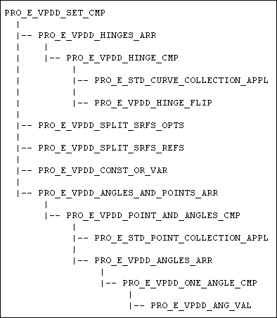
PRO_E_VPDD_SET_CMP
Image
The elements in this tree are as follows:
•  PRO_E_FEATURE_TYPE—Specifies the feature type and should be PRO_FEAT_VPDD.
•  PRO_E_STD_FEATURE_NAME—Specifies the name of the feature.
•  PRO_E_VPDD_PULL_DIR_CMP—Specifies the pull direction reference. This compound element consists of the following elements:
  PRO_E_VPDD_PULL_DIR_REF—Specifies the selected reference surface. It could be a single PRO_QUILT, a single PRO_DATUM_PLANE, a single PRO_LOG_SRF, or multiple PRO_SURFACE references that are tangent to each other.
  PRO_E_VPDD_PULL_DIR_FLIP—Specifies the pull direction defined by the normal vectors of the selected reference surfaces. By default, this element is PRO_B_TRUE and the pull direction is along the normal vectors. The pull direction can be flipped.
•  PRO_E_VPDD_SETS_ARR—Specifies an array of the elements of the type PRO_E_VPDD_SET_CMP. PRO_E_VPDD_SET_CMP is a compound element and specifies a draft set. For more information on the elements contained by this compound element, refer to the section Element Details of the Subtree PRO_E_VPDD_SET_CMP.
•  PRO_E_VPDD_ATTACH_OPTS—Specifies the attachment option. When all the draft hinges are two-sided edges, you can specify whether to attach the draft geometry to the existing solid or quilt, or create the draft geometry as a separate quilt. The attachment options, specified by the enumerated type Pro_vpdd_attach_type, are as follows:
  PRO_VPDD_ATTACH_NEW_QUILT—Creates the draft geometry as a separate quilt.
  PRO_VPDD_ATTACH_SAME_QUILT—Attaches the draft geometry to the existing solid or quilt.
•  PRO_E_VPDD_EXTENT_CMP—Specifies the extent (depth) option when unattached draft geometry is created. This compound element is available only if the element PRO_E_VPDD_ATTACH_OPTS is set to PRO_VPDD_ATTACH_NEW_QUILT.
  PRO_E_VPDD_EXT_OPTS—Specifies the extent options. These options, specified by the enumerated type Pro_vpdd_extent_type, are as follows:
  PRO_VPDD_EXT_LENGTH—Specifies the length dimension option.
  PRO_VPDD_EXT_TO_SEL—Select the reference bottom surface upto which the draft geometry is extended.
  PRO_VPDD_EXT_TO_NEXT—The draft geometry is extended up to the next surface it intersects. This excludes any surface or quilt used as a parting surface for a different draft set.
  PRO_VPDD_EXT_UNATTACHED—Creates the draft geometry ready for attachment but as a separate quilt.
  PRO_E_VPDD_EXT_LENGTH—Specifies the length value. This element is available only when the element PRO_E_VPDD_EXT_OPTS is set to PRO_VPDD_EXT_LENGTH.
  PRO_E_VPDD_EXT_REF—Specifies the selected bottom surface upto which the draft geometry is extended. The valid references are PRO_QUILT, PRO_SURFACE, and PRO_DATUM_PLANE. This element is available only when the element PRO_E_VPDD_EXT_OPTS is set to PRO_VPDD_EXT_TO_SEL.
Element Details of the Subtree PRO_E_VPDD_SET_CMP
The compound element PRO_E_VPDD_SET_CMP contains the following elements:
•  PRO_E_VPDD_HINGES_ARR—Specifies an array of elements of the type PRO_E_VPDD_HINGE_CMP. PRO_E_VPDD_HINGE_CMP is a compound element and specifies a collection of draft hinges used to generate the draft geometry.
  PRO_E_STD_CURVE_COLLECTION_APPL—Specifies a chain of two-sided edges, one-sided edges, curves, or a combination of one-sided edges and curves.
  PRO_E_VPDD_HINGE_FLIP—Specifies the ProBoolean option to select the sets of surfaces to be drafted on each side of a draft hinge defined by two-sided edges.
•  PRO_E_VPDD_SPLIT_SRFS_OPTS—Specifies the ProBoolean option to specify if splitting surfaces are used while generating the draft geometry. If this option is set to the default value PRO_B_FALSE, then the element PRO_E_VPDD_SPLIT_SRFS_REFS becomes unavailable.
•  PRO_E_VPDD_SPLIT_SRFS_REFS—Specifies a collection of splitting surface references. You can select upto two references that are either PRO_QUILT or PRO_DATUM_PLANE.
•  PRO_E_VPDD_CONST_OR_VAR—Specifies a constant or variable draft. For a variable draft, there are variable angle attachment points. The values for this element, specified by the enumerated type Pro_vpdd_const_var_type, are as follows:
  PRO_VPDD_CONST
  PRO_VPDD_VAR
•  PRO_E_VPDD_ANGLES_AND_POINTS_ARR—Specifies an array of elements of the type PRO_E_VPDD_POINT_AND_ANGLES_CMP. PRO_E_VPDD_POINT_AND_ANGLES_CMP is a compound element and specifies a collection of points and angles.
  PRO_E_STD_POINT_COLLECTION_APPL—Specifies the selection references (curves, edges, or datum points) where the draft angles are defined.
Note
  If PRO_E_VPDD_CONST_OR_VAR is set to PRO_VPDD_CONST, then the element PRO_E_STD_POINT_COLLECTION_APPL becomes unavailable and the element PRO_E_VPDD_ANGLES_AND_POINTS_ARR contains only a single element.
  A reference is valid when it belongs to or lies on a draft hinge that belongs to the same draft set.
  PRO_E_VPDD_ANGLES_ARR—Specifies an array of elements of the type PRO_E_VPDD_ONE_ANGLE_CMP. The size of the array is one plus the number of splitting references. PRO_E_VPDD_ONE_ANGLE_CMP is a compound element and specifies the draft angle for the active draft set.
  PRO_E_VPDD_ANG_VAL—Specifies the value of the draft angle. This value lies in the range of -90 degrees through 90 degrees.
Creating a VPDD
Function Introduced:
Use the function ProFeatureCreate() to create a VPDD based on element tree input. For more information about ProFeatureCreate(), refer to the section Overview of Feature Creation of Element Trees: Principles of Feature Creation.
Redefining a VPDD
Function Introduced:
Use the function ProFeatureRedefine() to redefine a VPDD based on the changes made in the element tree. For more information about ProFeatureRedefine(), refer to the section Feature Redefine of Element Trees: Principles of Feature Creation.
Accessing a VPDD
Function Introduced:
Use the function ProFeatureElemtreeExtract() to create a feature element tree that describes the contents of a VPDD and to retrieve the element tree description of a Draft. For more information about ProFeatureElemtreeExtract() refer to the section Feature Inquiry of Element Trees: Principles of Feature Creation.