Element Trees: Solid Body
This section describes the element tree structure for body options that can be selected while creating a feature. You can perform geometric operations such as splitting a body or merging with other bodies and boolean operations such as merge, intersect, and subtract.
The following sections describe the procedure for performing Boolean operations such as intersect, subtract, and, merge bodies in a model. This chapter also describes how to copy, remove, and split bodies.
Introduction
Using Creo TOOLKIT, you can create bodies. The creation and manipulation of bodies use the following Creo TOOLKIT objects:
•  ProSolid
•  ProSolidBody
The Element Tree for Body Options
The element tree for Body options is documented in the Creo Parametric header file ProBodyOpts.h.
The following figure shows the element tree for body options feature.
The Element Tree for Body Options Feature
Image
The following table describes the elements in the element tree:
Element ID
Data Type
Description
PRO_E_BODY
Compound element
Compound element for body options.
PRO_E_BODY_USE
PRO_VALUE_TYPE_INT
Mandatory. Specifies the body to add geometry to.
Defined by the enumerated data type ProBodyUseOpts and the valid values follow:
•  PRO_BODY_USE_NEW— Feature stores its geometry in the new body.
•  PRO_BODY_USE_ALL—Feature cuts from all existing bodies.
•  PRO_BODY_USE_SELECTED—Feature adds or removes its geometry to or from selected bodies.
PRO_E_BODY_SELECT
PRO_VALUE_TYPE_SELECTION
Specifies the reference to the selected bodies.
Mandatory if PRO_E_BODY_USE is set to PRO_BODY_USE_SELECTED.
The Element Tree for Body Copy Feature
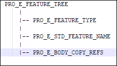
You can perform copy operation on bodies. When you copy bodies in a part, a new body is created for each source body. The element tree for the body copy feature is documented in the Creo Parametric header file ProBodyCopy.h.
The Element Tree for Body Copy Feature
The following figure shows the element tree for the body copy feature.
Image
The following table describes the elements in the element tree:
Element ID
Data Type
Description
PRO_E_FEATURE_TYPE
PRO_VALUE_TYPE_INT
Specifies the feature type. Valid value is PRO_FEAT_BODY_COPY.
PRO_E_STD_FEATURE_NAME
PRO_VALUE_TYPE_WSTRING
Specifies the feature name.
PRO_E_BODY_COPY_REFS
PRO_VALUE_TYPE_SELECTION
Mandatory. Specifies the bodies to copy. Only bodies from the same model are allowed.
Note
Use the function ProElementReferencesSet(), if you need to set multiple reference values for PRO_E_BODY_COPY_REFS.
The Element Tree for Body Split Feature
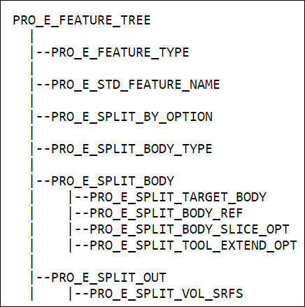
You can split a body into two bodies. The geometry of the original body is divided between the original body and the new body. The element tree for the body split feature is documented in the Creo Parametric header file ProSplitbody.h.
The Element Tree for Body Split Feature
The following figure shows the element tree for the split body feature.
Image
The following table describes the elements in the element tree:
Element ID
Data Type
Description
PRO_E_STD_FEATURE_NAME
PRO_VALUE_TYPE_WSTRING
Name of the feature.
PRO_E_SPLIT_BY_OPTION
PRO_VALUE_TYPE_INT
Mandatory element.
Split by option.
PRO_E_SPLIT_BODY_TYPE
PRO_VALUE_TYPE_INT
Split Operation. The element is defined by the enumerated data type ProSplitOperation and the valid values are:
•  PRO_SPLIT_BODY—Split the body into two bodies.
•  PRO_TRIM_BODY—Trim the body.
PRO_E_SPLIT_BODY
Compound element
Split by object.
PRO_E_SPLIT_TARGET_BODY
PRO_VALUE_TYPE_SELECTION
Target body to be split.
PRO_E_SPLIT_BODY_REF
PRO_VALUE_TYPE_SELECTION
Split by body reference.
PRO_E_SPLIT_BODY_SLICE_OPT
PRO_VALUE_TYPE_INT
Split by slice direction.
PRO_E_SPLIT_TOOL_EXTEND_OPT
PRO_VALUE_TYPE_INT
Split by extended object.
PRO_E_SPLIT_OUT
Compound element
Split by volume.
PRO_E_SPLIT_VOL_SRFS
PRO_VALUE_TYPE_SELECTION
Split by surfaces.
Splitting by Object
You can split one body into two bodies using a plane, surface, or quilt as the splitting object. The following table lists the mandatory element types for splitting a body by object:
Element ID
Data Type
PRO_E_SPLIT_BY_OPTION
The valid value is PRO_SPLIT_BY_SPLITTING_OBJ of the enumerated data type ProSplitByType.
PRO_E_SPLIT_TARGET_BODY
Target bodies to be split.
PRO_E_SPLIT_BODY_REF
Split by body reference.
PRO_E_SPLIT_BODY_SLICE_OPT
Side 1 / Side 2 of the enumerated data type ProSplitBodySliceOpt.
PRO_E_SPLIT_TOOL_EXTEND_OPT
Extend option of the enumerated data type ProSplitBodyToolExtendOpt.
Splitting by Volume type
When the geometry of the original body has disjoint volumes, you can split out one or more of these volumes into a new body. Select one or more body surfaces to define that volume as a new body. The following table lists the mandatory element types for splitting a body by volume type:
Element ID
Data Type
PRO_E_SPLIT_BY_OPTION
The valid value is PRO_SPLIT_BY_VOLUME of the enumerated data type ProSplitByType.
PRO_E_SPLIT_VOL_SRFS
Split by surfaces or surface regions.
A body can be divided into two bodies by an intersecting object or by volume. The enumerated data type ProSplitByType defines the way the body is split and has the following valid values:
•  PRO_SPLIT_BY_SPLITTING_OBJ—A body can be split by an intersecting object.
•  PRO_SPLIT_BY_VOLUME—A body that has more than one disjoint volume can be split by picking up the surface or surface regions of the desired portion to split out as a new body.
The splitting side of the body is defined by the enumerated data type ProSplitBodySliceOpt. When a single body is split, an additional body is created. The valid values follow:
•  PRO_E_SPLIT_BODY_SLICE_FIRST_OPT—Side 1 is the default option and the value is 0.
•  PRO_E_SPLIT_BODY_SLICE_SECOND_OPT—Flips the default body creation and creates a body in the other side.
The extend object is available for splitting by object and is defined by the enumerated data type ProSplitBodyToolExtendOpt and has the following valid values:
•  PRO_E_SPLIT_TOOL_EXTEND_OPT_NO—The splitting object intersects the body graphically.
•  PRO_E_SPLIT_TOOL_EXTEND_OPT_YES—The splitting object is extended to intersect with the bodies. The extend option is available for the geometrically extendable objects such as a plane.
The Element Tree for Body Remove Feature
As part of multibody design, there could be bodies that you want to remove from the model. For example, you created bodies as tools in the design process and you do not need them in the final model, or the system created bodies when you imported geometry from other models. You cannot delete these bodies, because they have contributing features. In such cases, you can remove the bodies.
Note
Bodies that are removed do not contribute to mass properties.
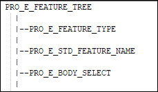
The element tree for the body remove feature is documented in the Creo Parametric header file ProRemoveBody.h. Using this element tree you can remove bodies in a model.
The Element Tree for Body Remove Feature
The following figure shows the element tree for the body remove feature.
Image
The following table describes the elements in the element tree:
Element ID
Data Type
Description
PRO_E_FEATURE_TYPE
PRO_VALUE_TYPE_INT
Specifies the feature type. The valid value is PRO_FEAT_REMOVEBODY.
PRO_E_STD_FEATURE_NAME
PRO_VALUE_TYPE_WSTRING
Specifies the feature name. Default value is Remove body.
PRO_E_BODY_SELECT
PRO_VALUE_TYPE_SELECTION
Mandatory. Specifies the references for the bodies that needs to be removed. The valid selection reference is from PRO_BODY type only.
Note
Use the function ProElementReferencesSet(), if you need to set multiple reference values for PRO_E_BODY_SELECT.
The Element Tree for Boolean Body Operations
When a part contains more than one body, you can use the Boolean Operations feature to perform geometric operations such as Merge, Intersect, and Subtract.
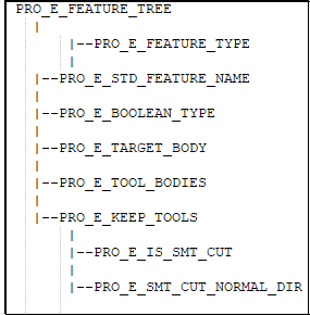
The element tree for Boolean body operations is documented in the Creo Parametric header file ProBooleanBodies.h. You can perform subtract, merge, and intersect operations on bodies.
The Element Tree for The Element Tree for Boolean Body Operation
The following figure shows the element tree for Boolean body operation.
Image
The following table describes the elements in the element tree:
Element ID
Data Type
Description
PRO_E_FEATURE_TYPE
PRO_VALUE_TYPE_INT
Specifies the feature type. The valid value is PRO_FEAT_BOOLEANBODIES.
PRO_E_STD_FEATURE_NAME
PRO_VALUE_TYPE_WSTRING
Specifies the feature name for combined Boolean body.
Default value depends on the operation type:
•  Body Merge
•  Body Intersect
•  Body Subtract
PRO_E_BOOLEAN_TYPE
PRO_VALUE_TYPE_INT
Specifies the Boolean operation type that needs to be performed on the bodies and is defined by the enumerated data type ProBooleanbodiesTypeOption. The valid values are:
•  MERGE_BOOL_TYPE—Body Merge
•  INTERSECT_BOOL_TYPE—Body Intersect
•  SUBTRACT_BOOL_TYPE—Body Subtract
PRO_E_TARGET_BODY
PRO_VALUE_TYPE_SELECTION
Specifies the reference to the modified bodies.
Mandatory element and can be filled with single body MERGE_BOOL_TYPE or INTERSECT_BOOL_TYPE or multiple bodies SUBTRACT_BOOL_TYPE .
The valid selection reference is from PRO_BODY type only.
Note
Use the function ProElementReferencesSet(), if you need to set multiple reference values for PRO_E_TARGET_BODY.
PRO_E_TOOL_BODIES
PRO_VALUE_TYPE_SELECTION
Specifies the reference to the modifying bodies.
Mandatory element and can be filled with single body SUBTRACT_BOOL_TYPE or multiple bodies MERGE_BOOL_TYPE or INTERSECT_BOOL_TYPE.
The valid selection reference is from PRO_BODY type only.
PRO_E_KEEP_TOOLS
PRO_VALUE_TYPE_INT
This element type is available only for SUBTRACT_BOOL_TYPE Boolean body operation. It specifies the body options that need to be kept. This element type is defined by the enumerated data type ProBooleanbodiesKeepBodyOption and the valid values are:
•  KEEP_TOOL_NO—default value. Deletes the modifying bodies.
•  KEEP_TOOL_YES—keeps the modifying bodies.
PRO_E_IS_SMT_CUT
PRO_VALUE_TYPE_INT
This element is applicable in sheetmetal parts only and it controls the cut type as follows:
•  PRO_B_TRUE—SMT cut type
•  PRO_B_FALSE—Solid cut type
PRO_E_SMT_CUT_NORMAL_DIR
PRO_VALUE_TYPE_INT
This element is applicable in sheetmetal parts only and it controls the SMT cut geometry driving surface.
The element type is defined by the enumerated data type ProSmtCutNormDir and the valid values are:
•  PRO_SMT_CUT_DRVSIDE_GREEN—For normal to Driven surface.
•  PRO_SMT_CUT_DRVSIDE_WHITE —For normal to Offset surface.