Production Applications: Creo NC Sequences, Operations and Work Centers
This section describes the Creo TOOLKIT support for Creo NC sequences.
Overview
This section describes the Creo TOOLKIT functions that enable you to access the following types of manufacturing features of Creo NC Sequences, Operations and Work Centers.
Creo NC Step
Header File
Roughing
ProMfgFeatRoughing.h
Reroughing
ProMfgFeatReroughing.h
Finishing
ProMfgFeatFinishing.h
Corner Finishing
ProMfgFeatCornerFinishing.h
2Axis Curve Trajectory Milling
ProMfgFeat2xCurvTraj.h
3Axis Trajectory Milling
ProMfgFeatTrajectory.h
Profile Milling
ProMfgFeatProfMilling.h
Manual Cycle
ProMfgFeatManualCycle.h
Thread Milling
ProMfgFeatThreadMilling.h
Area Turning
ProMfgFeatTurning.h
Groove Turning
ProMfgFeatTurning.h
Profile Turning
ProMfgFeatTurning.h
Face Milling
ProMfgFeatFacing.h
Creo NC Operation Definition
ProMfgFeatOperation.h
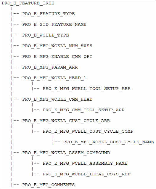
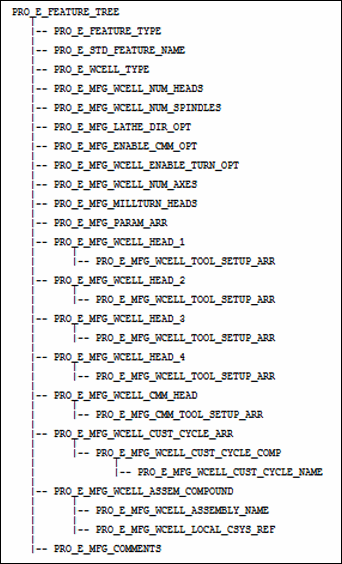
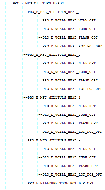
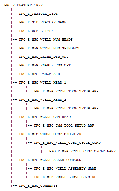
Workcell Definition
ProMfgFeatWcellWedm.h
ProMfgFeatWcellMill.h
ProMfgFeatWcellMillTurn.h
ProMfgFeatWcellLathe.h
ProMfgFeatWcellCmm.h
Fixture Definition
ProMfgFeatFixture.h
Thread Turning
ProMfgFeatTurnThread.h
Holemaking
ProMfgFeatHolemaking.h
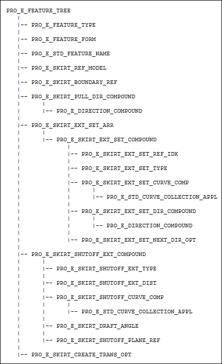
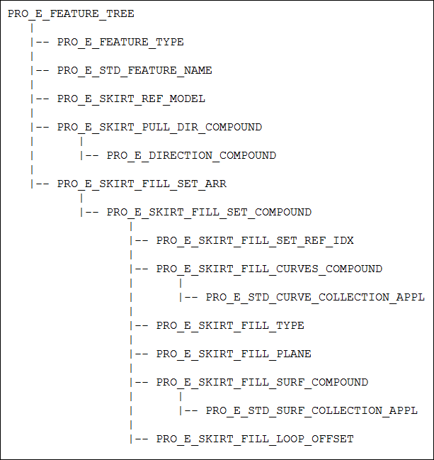
Shut-off Surface Feature
ProMoldShutSrf.h
Round and Chamfer
ProMfgFeatRoundChamferMilling.h
Engraving
ProMfgFeatEngraving.h
Cutline Milling
ProMfgFeatCutlineMilling.h
Drill Group Feature
ProMfgFeatDrillGroup.h
Element Trees: Roughing Step
This section describes how to construct and access the element tree for a milling roughing feature. It also describes how to create, redefine, and access the properties of these features.
The Roughing Feature Element Tree:
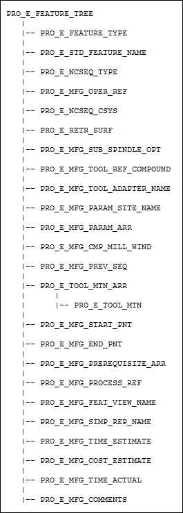
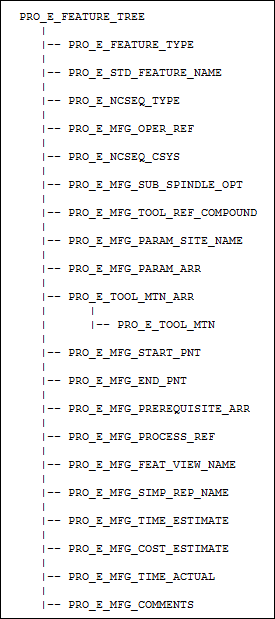
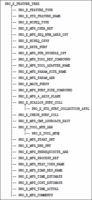
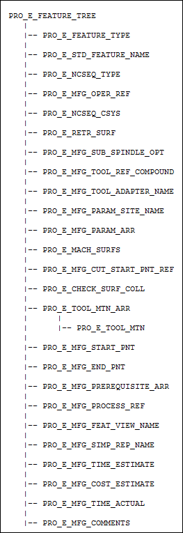
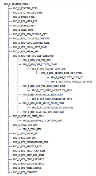
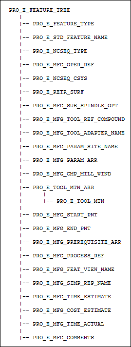
The element tree for the milling roughing sequence is documented in the header file ProMfgFeatRoughing.h, and is as shown in the following figure:
Element Tree for Roughing feature
Image
The following table describes the elements in the element tree for the Roughing feature.
Element ID
Data Type
Description
PRO_E_FEATURE_TYPE
PRO_VALUE_TYPE_INT
Mandatory element. Specifies the type of the feature. The valid value for this element is PRO_FEAT_MILL.
PRO_E_STD_FEATURE_NAME
PRO_VALUE_TYPE_WSTRING
Optional element. Specifies the name for the Creo NC sequence. The default value is Roughing_1.
PRO_E_NCSEQ_TYPE
PRO_VALUE_TYPE_INT
Mandatory element. Specifies the type of Creo NC sequence. The valid value for this element is PRO_NCSEQ_ROUGHVOL_MILL.
PRO_E_MFG_OPER_REF
PRO_VALUE_TYPE_SELECTION
Mandatory element. Specifies the operation feature selection.
PRO_E_NCSEQ_CSYS
PRO_VALUE_TYPE_SELECTION
Mandatory element. Specifies the datum coordinate system that will be used as the coordinate system for the Creo NC sequence.
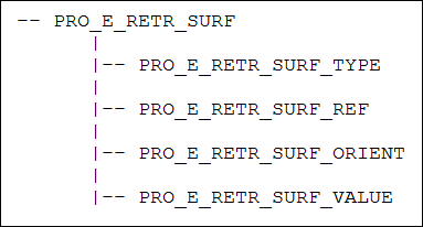
PRO_E_RETR_SURF
Compound
Mandatory compound element. Specifies retract definition. For more information, refer to the section Retract Elements.
PRO_E_MFG_SUB_SPINDLE_OPT
PRO_VALUE_TYPE_INT
Optional Element. Specifies the type of spindle assigned to the sequence. This element can be used when two parts are machined during the same operation in different spindles, that is in the main spindle and in the sub spindle. The valid values for this element are defined by the enumerated type ProSubSpindleOpt. For more information on the values of ProSubSpindleOpt, refer to the section Spindle Types
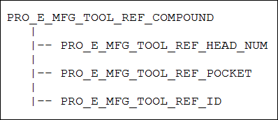
PRO_E_MFG_TOOL_REF_COMPOUND
Compound
Mandatory compound element. Specifies tool reference definition. For more information, refer to the section Tool Reference.
PRO_E_MFG_TOOL_ADAPTER_NAME
PRO_VALUE_TYPE_WSTRING
Optional element. Specifies the tool adapter model name.
PRO_E_MFG_PARAM_SITE_NAME
PRO_VALUE_TYPE_WSTRING
Optional element. Specifies the name of the site file with default values for manufacturing parameters.
Note
The site file name will be ignored if the site does not exist in the manufacturing model.
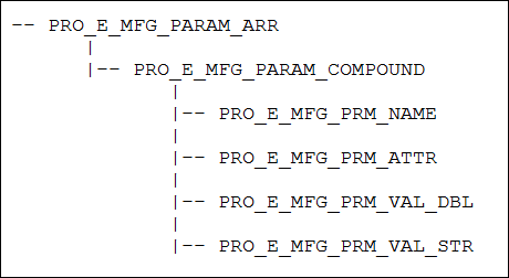
PRO_E_MFG_PARAM_ARR
Array
Mandatory element. Defines an array of manufacturing parameters. For more information, refer to the section Manufacturing Parameters.
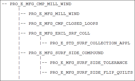
PRO_E_MFG_CMP_MILL_WIND
Compound
Mandatory compound element. Specifies the mill window compound definition. For more information, refer to the section Surface Collection with Mill Window.
PRO_E_TOOL_MTN_ARR
Array
Mandatory element. Specifies an array of tool motions.
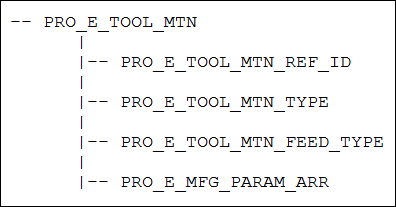
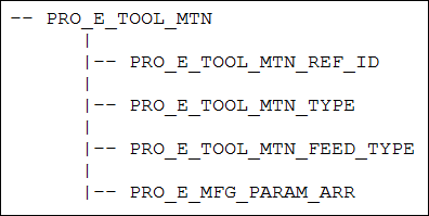
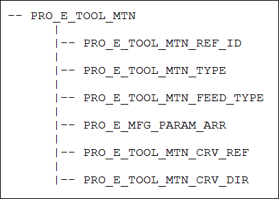
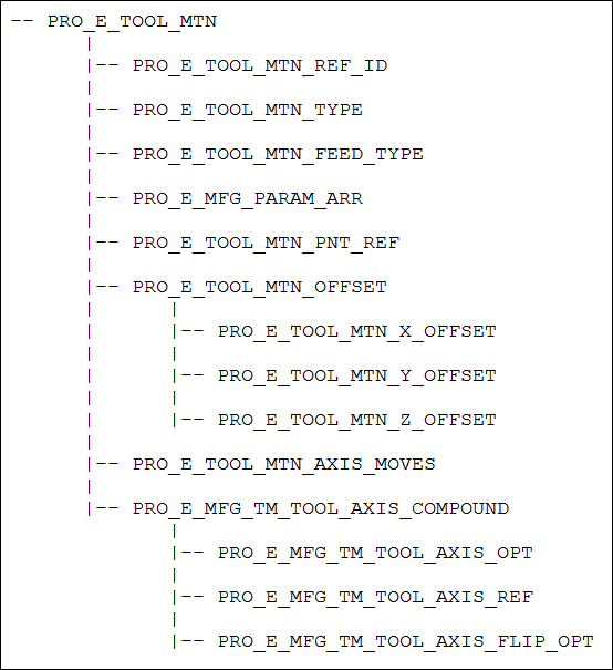
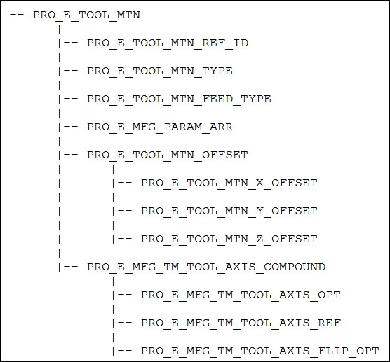
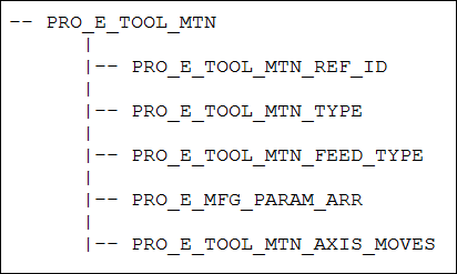
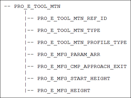
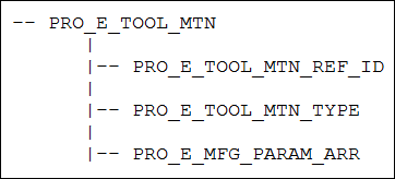
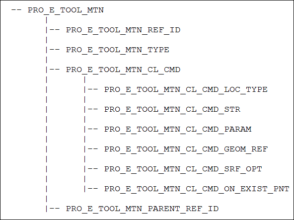
PRO_E_TOOL_MTN
Compound
Mandatory compound element. Specifies the tool motion compound specifications. The applicable tool motion type for this element is : PRO_TM_TYPE_AUTOMATIC_CUT.
For more information, refer to the section Tool Motion — Auto Cut.
PRO_E_MFG_START_PNT
PRO_VALUE_TYPE_SELECTION
Optional element. Specifies the datum point selection. It allows to start the machining at the specified position.
PRO_E_MFG_END_PNT
PRO_VALUE_TYPE_SELECTION
Optional element. Specifies the datum point selection. It allows to end the machining at the specified position.
PRO_E_MFG_PREREQUISITE_ARR
Array
Optional element. This array specifies the Ids of the prerequisite sequences. For more information, refer to the section Sequence Prerequisites.
PRO_E_MFG_PROCESS_REF
PRO_VALUE_TYPE_SELECTION
Optional element. Specifies the reference selections such as part, feature, curve, surface, datum plane, axis, point, and datum coordinate. It allows you to create additional geometric references to be used only in special process application. This element supports multiple selections.
PRO_E_MFG_FEAT_VIEW_NAME
PRO_VALUE_TYPE_WSTRING
Optional element. Specifies the name of the view. This element allows you to associate a specific view with the machining step.
Note
This element is used only in special process application.
PRO_E_MFG_SIMP_REP_NAME
PRO_VALUE_TYPE_WSTRING
Optional element. Specifies the simplified representation name. This element allows you to associate the specific simplified representation with the machining step.
Note
This element is used only in special process application.
PRO_E_MFG_TIME_ESTIMATE
PRO_VALUE_TYPE_DOUBLE
Optional element. Specifies the time estimated for the machining step.
Note
This element is used only in special process application.
PRO_E_MFG_COST_ESTIMATE
PRO_VALUE_TYPE_DOUBLE
Optional element. Specifies the cost estimate for the machining step.
Note
This element is used only in special process application.
PRO_E_MFG_TIME_ACTUAL
PRO_VALUE_TYPE_DOUBLE
Optional element. Specifies the actual time for the machining step.
Note
This element is used only in special process application.
PRO_E_MFG_COMMENTS
PRO_VALUE_TYPE_WSTRING
Specifies the sequence comments.
Element Trees: Reroughing Step
This section describes how to construct and access the element tree for a milling reroughing feature. It also describes how to create, redefine, and access the properties of these features.
The Reroughing Feature Element Tree:
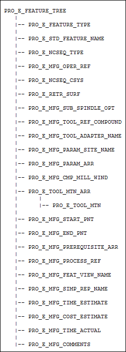
The element tree for the milling reroughing sequence is documented in the header file ProMfgFeatReroughing.h, and is as shown in the following figure:
Element Tree for Reroughing feature
Image
The following table describes the elements in the element tree for the Reroughing feature.
Element ID
Data Type
Description
PRO_E_FEATURE_TYPE
PRO_VALUE_TYPE_INT
Mandatory element. Specifies the type of the feature . The valid value for this element isPRO_FEAT_MILL.
PRO_E_STD_FEATURE_NAME
PRO_VALUE_TYPE_WSTRING
Optional element. Specifies the name for the Creo NC sequence feature name. The default value is Re-roughing_1.
PRO_E_NCSEQ_TYPE
PRO_VALUE_TYPE_INT
Mandatory element. Specifies the type of Creo NC sequence type. The valid value for this element is PRO_NCSEQ_REROUGH_MILL.
PRO_E_MFG_OPER_REF
PRO_VALUE_TYPE_SELECTION
Mandatory element. Specifies the operation feature selection.
PRO_E_NCSEQ_CSYS
PRO_VALUE_TYPE_SELECTION
Mandatory element. Specifies the datum coordinate system that will be used as the coordinate system for the Creo NC sequence.
PRO_E_RETR_SURF
Compound
Mandatory compound element. Specifies retract definition. For more information, refer to the section Retract Elements.
PRO_E_MFG_SUB_SPINDLE_OPT
PRO_VALUE_TYPE_INT
Optional Element. Specifies the type of spindle assigned to the sequence. This element can be used when two parts are machined during the same operation in different spindles, that is in the main spindle and in the sub spindle. The valid values for this element are defined by the enumerated type ProSubSpindleOpt. For more information on the values of ProSubSpindleOpt, refer to the section Spindle Types
PRO_E_MFG_TOOL_REF_COMPOUND
Compound
Mandatory compound element. Specifies tool reference definition. For more information, refer to the section Tool Reference.
PRO_E_MFG_TOOL_ADAPTER_NAME
PRO_VALUE_TYPE_WSTRING
Optional element. Specifies the tool adapter model name.
PRO_E_MFG_PARAM_SITE_NAME
PRO_VALUE_TYPE_WSTRING
Optional element. Specifies the name of the site file with default values for manufacturing parameters.
Note
The site file name will be ignored if the site does not exist in the manufacturing model.
PRO_E_MFG_PARAM_ARR
Array
Mandatory element. Defines an array of manufacturing parameters. For more information, refer to the section Manufacturing Parameters.
PRO_E_MFG_CMP_MILL_WIND
Compound
Mandatory compound element. Specifies the mill window compound definition. For more information, refer to the section Surface Collection with Mill Window.
PRO_E_MFG_PREV_SEQ
PRO_VALUE_TYPE_SELECTION
Mandatory Element. Specifies the selection sequence feature that requires removal of left over material. The valid values for this element are:
•  Volume Milling
•  Profile Milling
•  Re-roughing sequence
PRO_E_TOOL_MTN_ARR
Array
Mandatory element. Specifies an array of tool motions.
PRO_E_TOOL_MTN
Compound
Mandatory compound element. Specifies the tool motion compound specifications. The applicable tool motion type for this element is PRO_TM_TYPE_AUTOMATIC_CUT. For more information, refer to the section Tool Motion — Auto Cut .
PRO_E_MFG_START_PNT
PRO_VALUE_TYPE_SELECTION
Optional element. Specifies the datum point selection. It allows to start the machining at the specified position.
PRO_E_MFG_END_PNT
PRO_VALUE_TYPE_SELECTION
Optional element. Specifies the datum point selection. It allows to end the machining at the specified position.
PRO_E_MFG_PREREQUISITE_ARR
Array
Optional element. This array specifies the Ids of the prerequisite sequences. For more information, refer to the section Sequence Prerequisites.
PRO_E_MFG_PROCESS_REF
PRO_VALUE_TYPE_SELECTION
Optional element. Specifies the reference selections such as part, feature, curve, surface, datum plane, axis, point, and datum coordinate. It allows you to create additional geometric references to be used only in special process application. This element supports multiple selections.
PRO_E_MFG_FEAT_VIEW_NAME
PRO_VALUE_TYPE_WSTRING
Optional element. Specifies the name of the view. This element allows you to associate a specific view with the machining step.
Note
This element is used only in special process application.
PRO_E_MFG_SIMP_REP_NAME
PRO_VALUE_TYPE_WSTRING
Optional element. Specifies the simplified representation name. This element allows you to associate the specific simplified representation with the machining step.
Note
This element is used only in special process application.
PRO_E_MFG_TIME_ESTIMATE
PRO_VALUE_TYPE_DOUBLE
Optional element. Specifies the time estimated for the machining step.
Note
This element is used only in special process application.
PRO_E_MFG_COST_ESTIMATE
PRO_VALUE_TYPE_DOUBLE
Optional element. Specifies the cost estimate for the machining step.
Note
This element is used only in special process application.
PRO_E_MFG_TIME_ACTUAL
PRO_VALUE_TYPE_DOUBLE
Optional element. Specifies the actual time for the machining step..
Note
This element is used only in special process application.
PRO_E_MFG_COMMENTS
PRO_VALUE_TYPE_WSTRING
Specifies the sequence comments.
Element Trees: Finishing Step
This section describes how to construct and access the element tree for milling Finishing feature. It also describes how to create, redefine, and access the properties of these features.
The Finishing Feature Element Tree:
The element tree for the milling Finishing sequence is documented in the header file ProMfgFeatFinishing.h, and is as shown in the following figure:
Element Tree for Finishing feature
Image
The following table describes the elements in the element tree for the Finishing feature.
Element ID
Data Type
Description
PRO_E_FEATURE_TYPE
PRO_VALUE_TYPE_INT
Mandatory element. Specifies the type of the feature. The valid value for this element is PRO_FEAT_MILL.
PRO_E_STD_FEATURE_NAME
PRO_VALUE_TYPE_WSTRING
Optional element. Specifies the name for the Creo NC sequence. The default value is Finishing_1.
PRO_E_NCSEQ_TYPE
PRO_VALUE_TYPE_INT
Mandatory element. Specifies the type of Creo NC sequence. The valid value for this element is PRO_NCSEQ_CVNC_FINISH_MILL.
PRO_E_MFG_OPER_REF
PRO_VALUE_TYPE_SELECTION
Mandatory element. Specifies the operation feature selection.
PRO_E_NCSEQ_CSYS
PRO_VALUE_TYPE_SELECTION
Mandatory element. Specifies the datum coordinate system that will be used as the coordinate system for the Creo NC sequence.
PRO_E_RETR_SURF
Compound
Mandatory compound element. Specifies retract definition. For more information, refer to the section Retract Elements.
PRO_E_MFG_SUB_SPINDLE_OPT
PRO_VALUE_TYPE_INT
Optional Element. Specifies the type of spindle assigned to the sequence. This element can be used when two parts are machined during the same operation in different spindles, that is in the main spindle and in the sub spindle. The valid values for this element are defined by the enumerated type ProSubSpindleOpt. For more information on the values of ProSubSpindleOpt, refer to the section Spindle Types
PRO_E_MFG_TOOL_REF_COMPOUND
Compound
Mandatory compound element. Specifies tool reference definition. For more information, refer to the section Tool Reference.
PRO_E_MFG_TOOL_ADAPTER_NAME
PRO_VALUE_TYPE_WSTRING
Optional element. Specifies the tool adapter model name.
PRO_E_MFG_PARAM_SITE_NAME
PRO_VALUE_TYPE_WSTRING
Optional element. Specifies the name of the site file with default values for manufacturing parameters.
Note
The site file name will be ignored if the site does not exist in the manufacturing model.
PRO_E_MFG_PARAM_ARR
Array
Mandatory element. Defines an array of manufacturing parameters. For more information, refer to the section Manufacturing Parameters.
PRO_E_MFG_CMP_MILL_WIND
Compound
Mandatory compound element. Specifies the mill window compound definition. For more information, refer to the section Surface Collection with Mill Window.
PRO_E_TOOL_MTN_ARR
Array
Mandatory element. Specifies an array of tool motions.
PRO_E_TOOL_MTN
Compound
Mandatory compound element. Specifies the tool motion compound specifications. The applicable tool motion type for this element is : PRO_TM_TYPE_AUTOMATIC_CUT.
For more information, refer to the sectionTool Motion — Auto Cut .
PRO_E_MFG_START_PNT
PRO_VALUE_TYPE_SELECTION
Optional element. Specifies the datum point selection. It allows to start the machining at the specified position.
PRO_E_MFG_END_PNT
PRO_VALUE_TYPE_SELECTION
Optional element. Specifies the datum point selection. It allows to end the machining at the specified position.
PRO_E_MFG_PREREQUISITE_ARR
Array
Optional element. This array specifies the Ids of the prerequisite sequences. For more information, refer to the section Sequence Prerequisites .
PRO_E_MFG_PROCESS_REF
PRO_VALUE_TYPE_SELECTION
Optional element. Specifies the reference selections such as part, feature, curve, surface, datum plane, axis, point, and datum coordinate. It allows you to create additional geometric references to be used only in special process application. This element supports multiple selections.
PRO_E_MFG_FEAT_VIEW_NAME
PRO_VALUE_TYPE_WSTRING
Optional element. Specifies the name of the view. This element allows you to associate a specific view with the machining step.
Note
This element is used only in special process application.
PRO_E_MFG_SIMP_REP_NAME
PRO_VALUE_TYPE_WSTRING
Optional element. Specifies the simplified representation name. This element allows you to associate the specific simplified representation with the machining step.
Note
This element is used only in special process application.
PRO_E_MFG_TIME_ESTIMATE
PRO_VALUE_TYPE_DOUBLE
Optional element. Specifies the time estimated for the machining step.
Note
This element is used only in special process application.
PRO_E_MFG_COST_ESTIMATE
PRO_VALUE_TYPE_DOUBLE
Optional element. Specifies the cost estimate for the machining step.
Note
This element is used only in special process application.
PRO_E_MFG_TIME_ACTUAL
PRO_VALUE_TYPE_DOUBLE
Optional element. Specifies the actual time for the machining step.
Note
This element is used only in special process application.
PRO_E_MFG_COMMENTS
PRO_VALUE_TYPE_WSTRING
Specifies the sequence comments.
Element Trees: Corner Finishing Step
This section describes how to construct and access the element tree for a corner finishing step. It also describes how to create, redefine, and access the properties of these features.
The Corner Finishing Element Tree:
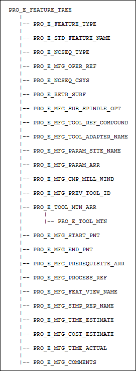
The element tree for the corner finishing sequence is documented in the header file ProMfgFeatCornerFinishing.h, and is as shown in the following figure:
Element Tree for Corner Finishing Step
Image
Element ID
Data Type
Description
PRO_E_FEATURE_TYPE
PRO_VALUE_TYPE_INT
Mandatory element. Specifies the type of the feature. The valid value for this element is PRO_FEAT_MILL.
PRO_E_STD_FEATURE_NAME
PRO_VALUE_TYPE_WSTRING
Optional element. Specifies the name for the Creo NC sequence. The default value is Corner_Finishing_1.
PRO_E_NCSEQ_TYPE
PRO_VALUE_TYPE_INT
Mandatory element. Specifies the type of Creo NC sequence. The valid value for this element is PRO_NCSEQ_CVNC_CORN_MILL.
PRO_E_MFG_OPER_REF
PRO_VALUE_TYPE_SELECTION
Mandatory element. Specifies the operation feature selection.
PRO_E_NCSEQ_CSYS
PRO_VALUE_TYPE_SELECTION
Mandatory element. Specifies the datum coordinate system that will be used as the coordinate system for the Creo NC sequence.
PRO_E_RETR_SURF
Compound
Mandatory compound element. Specifies retract definition. For more information, refer to the section Retract Elements.
PRO_E_MFG_SUB_SPINDLE_OPT
PRO_VALUE_TYPE_INT
Optional Element. Specifies the type of spindle assigned to the sequence. This element can be used when two parts are machined during the same operation in different spindles, that is in the main spindle and in the sub spindle. The valid values for this element are defined by the enumerated type ProSubSpindleOpt. For more information on the values of ProSubSpindleOpt, refer to the section Spindle Types
PRO_E_MFG_TOOL_REF_COMPOUND
Compound
Mandatory compound element. Specifies tool reference definition. For more information, refer to the section Tool Reference.
PRO_E_MFG_TOOL_ADAPTER_NAME
PRO_VALUE_TYPE_WSTRING
Optional element. Specifies the tool adapter model name.
PRO_E_MFG_PARAM_SITE_NAME
PRO_VALUE_TYPE_WSTRING
Optional element. Specifies the name of the site file with default values for manufacturing parameters.
Note
The site file name will be ignored if the site does not exist in the manufacturing model.
PRO_E_MFG_PARAM_ARR
Array
Mandatory element. Defines an array of manufacturing parameters. For more information, refer to the section Manufacturing Parameters.
PRO_E_MFG_CMP_MILL_WIND
Compound
Mandatory compound element. Specifies the mill window compound definition. For more information, refer to the section Surface Collection with Mill Window.
PRO_E_MFG_PREV_TOOL_ID
PRO_VALUE_TYPE_WSTRING
Optional element. Name of cutting tool (tool id) which will be used for calculating the remainder material.
PRO_E_TOOL_MTN_ARR
Array
Mandatory element. Specifies an array of tool motions.
PRO_E_TOOL_MTN
Compound
Mandatory compound element. Specifies the tool motion compound specifications. The applicable tool motion type for this element is : PRO_TM_TYPE_AUTOMATIC_CUT. For more information, refer to the section Tool Motion — Auto Cut .
PRO_E_MFG_START_PNT
PRO_VALUE_TYPE_SELECTION
Optional element. Specifies the datum point selection. It allows to start the machining at the specified position.
PRO_E_MFG_END_PNT
PRO_VALUE_TYPE_SELECTION
Optional element. Specifies the datum point selection. It allows to end the machining at the specified position.
PRO_E_MFG_PREREQUISITE_ARR
Array
Optional element. This array specifies the Ids of the prerequisite sequences. For more information, refer to the section Sequence Prerequisites .
PRO_E_MFG_PROCESS_REF
PRO_VALUE_TYPE_SELECTION
Optional element. Specifies the reference selections such as part, feature, curve, surface, datum plane, axis, point, and datum coordinate. It allows you to create additional geometric references to be used only in special process application. This element supports multiple selections.
PRO_E_MFG_FEAT_VIEW_NAME
PRO_VALUE_TYPE_WSTRING
Optional element. Specifies the name of the view. This element allows you to associate a specific view with the machining step.
Note
This element is used only in special process application.
PRO_E_MFG_SIMP_REP_NAME
PRO_VALUE_TYPE_WSTRING
Optional element. Specifies the simplified representation name. This element allows you to associate the specific simplified representation with the machining step.
Note
This element is used only in special process application.
PRO_E_MFG_TIME_ESTIMATE
PRO_VALUE_TYPE_DOUBLE
Optional element. Specifies the time estimated for the machining step.
Note
This element is used only in special process application.
PRO_E_MFG_COST_ESTIMATE
PRO_VALUE_TYPE_DOUBLE
Optional element. Specifies the cost estimate for the machining step.
Note
This element is used only in special process application.
PRO_E_MFG_TIME_ACTUAL
PRO_VALUE_TYPE_DOUBLE
Optional element. Specifies the actual time for the machining step.
Note
This element is used only in special process application.
PRO_E_MFG_COMMENTS
PRO_VALUE_TYPE_WSTRING
Specifies the sequence comments.
Element Trees: 3–Axis Trajectory Milling Step
This section describes how to construct and access the element tree for the 3 Axis Trajectory Milling feature. It also describes how to create, redefine, and access the properties of these features. For 2-axis curve trajectory milling step, refer to the section Manufacturing 2–Axis Curve Trajectory Milling Step.
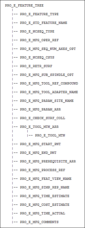
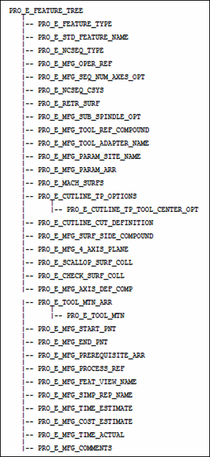
The element tree for the 3 axis trajectory milling sequence is documented in the header file ProMfgFeatTrajectory.h, and is as shown in the following figure:
Element Tree for 3 Axis Trajectory Milling feature
Image
The following table describes the elements in the element tree for the 3 Axis Trajectory Milling feature.
Element ID
Data Type
Description
PRO_E_FEATURE_TYPE
PRO_VALUE_TYPE_INT
Mandatory element. Specifies the type of the feature . The valid value for this element is PRO_FEAT_MILL.
PRO_E_STD_FEATURE_NAME
PRO_VALUE_TYPE_WSTRING
Optional element. Specifies the name for the Creo NC sequence . The default value is Trajectory_1.
PRO_E_NCSEQ_TYPE
PRO_VALUE_TYPE_INT
Mandatory element. Specifies the type of Creo NC sequence type. The valid value for this element isPRO_NCSEQ_TRAJ_MILL_STEP.
PRO_E_MFG_OPER_REF
PRO_VALUE_TYPE_SELECTION
Mandatory element. Specifies the operation feature selection.
PRO_E_MFG_SEQ_NUM_AXES_OPT
PRO_VALUE_TYPE_INT
Specifies the number of axes for milling. You can specify 3, 4, or 5 axes.
Note
You can set this element to 5 only if the work center allows 5-axis machining.
PRO_E_NCSEQ_CSYS
PRO_VALUE_TYPE_SELECTION
Mandatory element. Specifies the datum that will be used as the coordinate system for the Creo NC sequence.
PRO_E_RETR_SURF
Compound
Mandatory compound element. Specifies retract definition. For more information, refer to the section Retract Elements .
PRO_E_MFG_SUB_SPINDLE_OPT
PRO_VALUE_TYPE_INT
Optional Element. Specifies the type of spindle assigned to the sequence. This element can be used when two parts are machined during the same operation in different spindles, that is in the main spindle and in the sub spindle. The valid values for this element are defined by the enumerated type ProSubSpindleOpt. For more information on the values of ProSubSpindleOpt, refer to the section Spindle Types
PRO_E_MFG_TOOL_REF_COMPOUND
Compound
Mandatory compound element. Specifies tool reference definition. For more information, refer to the section Tool Reference .
PRO_E_MFG_TOOL_ADAPTER_NAME
PRO_VALUE_TYPE_WSTRING
Optional element. Specifies the tool adapter model name.
PRO_E_MFG_PARAM_SITE_NAME
PRO_VALUE_TYPE_WSTRING
Optional element. Specifies the name of the site file with default values for manufacturing parameters.
Note
The site file name will be ignored if the site does not exist in the manufacturing model.
PRO_E_MFG_PARAM_ARR
Array
Mandatory element. Defines an array of manufacturing parameters. For more information, refer to the section Manufacturing Parameters .
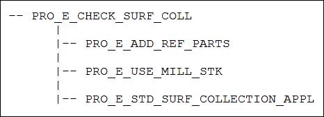
PRO_E_CHECK_SURF_COLL
PRO_VALUE_TYPE_SELECTION
Optional compound element. Specifies the check surfaces compound definition. For more information, refer to the section Checking Surfaces.
PRO_E_TOOL_MTN_ARR
Array
Mandatory element. Specifies an array of tool motions.
PRO_E_TOOL_MTN
Compound
Mandatory compound element. Specifies the tool motion compound specifications. The applicable tool motion types for this element are :
•  PRO_TM_TYPE_CURVE
_TRAJECTORY
. For more information, refer to the section Tool Motion — Curve Trajectory.
•  PRO_TM_TYPE_SURF_TRAJECTORY. For more information, refer to the section Tool Motion — Surface Trajectory.
•  PRO_TM_TYPE_FOLLOW_CUT. For more information, refer to the section Tool Motion — Follow Cut.
•  PRO_TM_TYPE_FOLLOW_CURVE. For more information, refer to the section Tool Motion — Follow Curve.
•  PRO_TM_TYPE_GOTO
_POINT
. For more information, refer to the section Tool Motion — Go To Point.
•  PRO_TM_TYPE_GO_DELTA. For more information, refer to the section Tool Motion — Go Delta.
•  PRO_TM_TYPE_GOHOME. For more information, refer to the section Tool Motion — Go Home.
•  PRO_TM_TYPE_PLUNGE. For more information, refer to the section Tool Motion — Plunge.
•  PRO_TM_TYPE_GO_RETRACT. For more information, refer to the section Tool Motion — Go Retract.
•  PRO_TM_TYPE_TANGENT_APPROACH. For more information, refer to the section Tool Motion — Tangent Approach.
•  PRO_TM_TYPE_TANGENT_EXIT. For more information, refer to the section Tool Motion — Tangent Exit.
•  PRO_TM_TYPE_NORMAL_APPROACH. For more information, refer to the section Tool Motion — Normal Approach.
•  PRO_TM_TYPE_NORMAL_EXIT. For more information, refer to the section Tool Motion — Normal Exit.
•  PRO_TM_TYPE_LEAD_IN. For more information, refer to the section Tool Motion — Lead In.
•  PRO_TM_TYPE_LEAD_OUT. For more information, refer to the section Tool Motion — Lead Out.
•  PRO_TM_TYPE_HELICAL_APPROACH. For more information, refer to the section Tool Motion — Helical Approach.
•  PRO_TM_TYPE_HELICAL_EXITFor more information, refer to the section Tool Motion — Helical Exit.
•  PRO_TM_TYPE_RAMP_EXIT. For more information, refer to the section Tool Motion — Ramp Exit.
•  PRO_TM_TYPE_CONNECT. For more information, refer to the section Tool Motion — Connect.
•  PRO_TM_TYPE_CL_COMMAND. For more information, refer to the section Tool Motion — CL Command.
PRO_E_MFG_START_PNT
PRO_VALUE_TYPE_SELECTION
Optional element. Specifies the datum point selection. It allows to start the machining at the specified position.
PRO_E_MFG_END_PNT
PRO_VALUE_TYPE_SELECTION
Optional element. Specifies the datum point selection. It allows to end the machining at the specified position.
PRO_E_MFG_PREREQUISITE_ARR
Array
Optional element. This array specifies the Ids of the prerequisite sequences. For more information, refer to the section Sequence Prerequisites .
PRO_E_MFG_PROCESS_REF
PRO_VALUE_TYPE_SELECTION
Optional element. Specifies the reference selections such as part, feature, curve, surface, datum plane, axis, point, and datum coordinate. It allows you to create additional geometric references to be used only in special process application. This element supports multiple selections.
PRO_E_MFG_FEAT_VIEW_NAME
PRO_VALUE_TYPE_WSTRING
Optional element. Specifies the name of the view. This element allows you to associate a specific view with the machining step.
Note
This element is used only in special process application.
PRO_E_MFG_SIMP_REP_NAME
PRO_VALUE_TYPE_WSTRING
Optional element. Specifies the simplified representation name. This element allows you to associate the specific simplified representation with the machining step.
Note
This element is used only in special process application.
PRO_E_MFG_TIME_ESTIMATE
PRO_VALUE_TYPE_DOUBLE
Optional element. Specifies the time estimated for the machining step.
Note
This element is used only in special process application.
PRO_E_MFG_COST_ESTIMATE
PRO_VALUE_TYPE_DOUBLE
Optional element. Specifies the cost estimate for the machining step.
Note
This element is used only in special process application.
PRO_E_MFG_TIME_ACTUAL
PRO_VALUE_TYPE_DOUBLE
Optional element. Specifies the actual time for the machining step.
Note
This element is used only in special process application.
PRO_E_MFG_COMMENTS
PRO_VALUE_TYPE_WSTRING
Specifies the sequence comments.
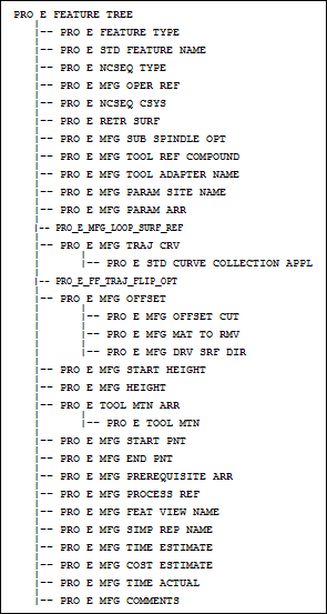
Manufacturing 2–Axis Curve Trajectory Milling Step
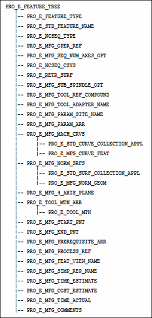
The element tree for the 2–axis curve trajectory sequence is documented in the header file ProMfgFeat2xCurvTraj.h, and is as shown in the following figure:
Image
The following table describes the elements in the element tree for the 2–axis curve trajectory sequence feature.
Element ID
Data Type
Description
PRO_E_FEATURE_TYPE
PRO_VALUE_TYPE_INT
Mandatory element. Specifies the type of the feature . The valid value for this element is PRO_FEAT_MILL.
PRO_E_STD_FEATURE_NAME
PRO_VALUE_TYPE_WSTRING
Optional element. Specifies the sequence feature name. The default value is Curve_Trajectory_1.
PRO_E_NCSEQ_TYPE
PRO_VALUE_TYPE_INT
Mandatory element. Specifies the type of Creo NC sequence type. The valid value for this element isPRO_NCSEQ_FF_TRAJ_MILL.
PRO_E_MFG_OPER_REF
PRO_VALUE_TYPE_SELECTION
Mandatory element. Specifies the operation feature selection.
PRO_E_NCSEQ_CSYS
PRO_VALUE_TYPE_SELECTION
Mandatory element. Specifies the coordinate system datum feature to be used as a sequence coordinate system.
PRO_E_RETR_SURF
Compound
Mandatory element. Specifies the retract compound definition. The element tree for the Retract Elements is defined in the section Retract Elements. For more information, refer to the section Retract Elements for more information on the element tree.
PRO_E_MFG_SUB_SPINDLE_OPT
PRO_VALUE_TYPE_INT
Optional Element. Specifies the type of spindle assigned to the sequence. This element can be used when two parts are machined during the same operation in different spindles, that is in the main spindle and in the sub spindle. The valid values for this element are defined by the enumerated type ProSubSpindleOpt. For more information on the values of ProSubSpindleOpt, refer to the section Spindle Types
PRO_E_MFG_TOOL_REF_COMPOUND
Compound
Mandatory element. Specifies the tool reference compound definition. The element tree for the Tool Reference is defined in the header file ProMfgElemToolRef.h. For more information, refer to the section Tool Referencefor more information on the element tree.
PRO_E_MFG_TOOL_ADAPTER_NAME
PRO_VALUE_TYPE_WSTRING
Optional element. Specifies the tool adapter model name
PRO_E_MFG_PARAM_SITE_NAME
PRO_VALUE_TYPE_WSTRING
Optional element. Specifies the name of site with default values for manufacturing parameters.
Note
The name is going to be ignored if site does not exist in the manufacturing model.
PRO_E_MFG_PARAM_ARR
Array
Mandatory element. Specifies an array of manufacturing parameters. See the Creo NC online help for more information on manufacturing parameters. The element tree for the manufacturing parameter is defined in the header file ProMfgElemParam.h. For more information, refer to the section Manufacturing Parameters for more information on the element tree.
PRO_E_MFG_LOOP_SURF_REF
PRO_VALUE_TYPE_SELECTION
Optional element. Select the surfaces for which the loops of edges must be collected. The collected loops of edges are machined.
PRO_E_MFG_TRAJ_CRV
Compound
Mandatory element. Specifies the machining curves compound definition.
PRO_E_STD_CURVE_COLLECTION_APPL
Curve Collection
Mandatory element. Specifies the curve collection.
PRO_E_FF_TRAJ_FLIP_OPT
PRO_VALUE_TYPE_INT
Optional element. Flips the machining direction of the tool. The valid values for this element are:
•  PRO_B_TRUE—Specifies that the default direction on the curve will be used.
•  PRO_B_FALSE—Specifies that the opposite direction on the curve will be used.
PRO_E_MFG_OFFSET
Compound
Optional element. Specifies the offset compound definition.
PRO_E_MFG_OFFSET_CUT
PRO_VALUE_TYPE_INT
Optional element. Specifies the offset cut. The valid values for this element are:
•  PRO_B_TRUE—Tool offset will be applied.
•  PRO_B_FALSE—Tool offset will not be applied.
PRO_E_MFG_MAT_TO_RMV
PRO_VALUE_TYPE_INT
Optional element. Specifies the material side. The valid values for this element are:
•  PRO_MFG_DIR_SAME
—Specifies the default side will be used.
•  PRO_MFG_DIR_OPPOSITE—Specifies that the default side will be flipped.
PRO_E_MFG_DRV_SRF_DIR
PRO_VALUE_TYPE_INT
Optional element. Specifies the flip drive Surface direction. The valid values for this element are:
•  PRO_B_FALSE—Specifies that the default direction on the drive surface will be used.
•  PRO_B_TRUE—Specifies that the opposite direction on the drive surface will be used.
PRO_E_MFG_START_HEIGHT
PRO_VALUE_TYPE_SELECTION
Optional element. Specifies the selection of the plane where machining will begin.
PRO_E_MFG_HEIGHT
PRO_VALUE_TYPE_SELECTION
Optional element. Specifies single selection of the plane for the tool tip to follow.
PRO_E_TOOL_MTN_ARR
Array
Optional element. Specifies an array of tool motions.
PRO_E_TOOL_MTN
Compound
Optional element. Specifies the tool motion compound specification.
PRO_E_MFG_START_PNT
PRO_VALUE_TYPE_SELECTION
Optional element. Specifies the datum point selection. Allows to start machining at the specified position.
PRO_E_MFG_END_PNT
PRO_VALUE_TYPE_SELECTION
Optional element. Specifies the datum point selection. Allows to end machining at the specified position.
PRO_E_MFG_PREREQUISITE_ARR
Array
Optional element. Specifies the array of ids of prerequisite sequences. The element tree for the Sequence Prerequisites is defined in the header file ProMfgElemPrerequisite.h. For more information, refer to the section Sequence Prerequisites for more information on the element tree.
PRO_E_MFG_PROCESS_REF
PRO_VALUE_TYPE_SELECTION
Optional element. Specifies the reference selections such as part, feature, curve, surface, datum plane, axis, point, and datum coordinate. It allows you to create additional geometry references to be used only in special process application. This element supports multiple selections.
PRO_E_MFG_FEAT_VIEW_NAME
PRO_VALUE_TYPE_WSTRING
Optional element. Specifies the view name. It allows you to associate specific view with a machining step.
Note
This element is used only in special process application.
PRO_E_MFG_SIMP_REP_NAME
PRO_VALUE_TYPE_WSTRING
Optional element. Specifies the simplified representation name. It allows you to associate a specific simplified representation with a machining step.
Note
This element is used only in special process application.
PRO_E_MFG_TIME_ESTIMATE
PRO_VALUE_TYPE_DOUBLE
Optional element. Specifies the time estimate. It allows you to specify time estimate for the machining step.
Note
This element is used only in special process application.
PRO_E_MFG_COST_ESTIMATE
PRO_VALUE_TYPE_DOUBLE
Optional element. Specifies the cost estimate. It allows you to specify cost estimate for the machining step.
Note
This element is used only in special process application.
PRO_E_MFG_TIME_ACTUAL
PRO_VALUE_TYPE_DOUBLE
Optional element. Specifies the actual time. It allows you to specify actual time for the machining step
Note
This element is used only in special process application.
PRO_E_MFG_COMMENTS
PRO_VALUE_TYPE_WSTRING
Specifies the sequence comments.
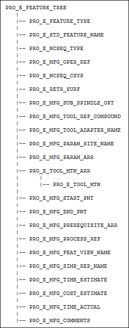
Element Trees: Manual Cycle Step
This section describes how to construct and access the element tree for manual milling cycle feature. It also describes how to create, redefine, and access the properties of these features.
The Manual Cycle Step Feature Element Tree:
The element tree for the manual cycle step feature is documented in the header file ProMfgFeatManualCycle.h, and is as shown in the following figure:
Element Tree for Manual Cycle Step feature
Image
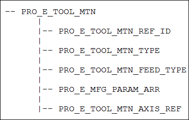
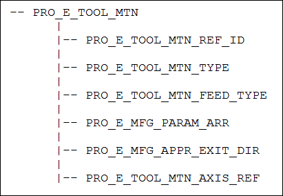
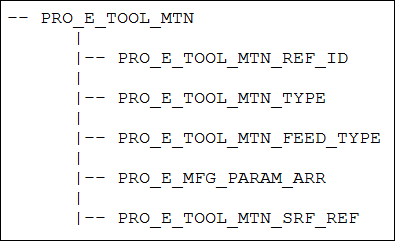
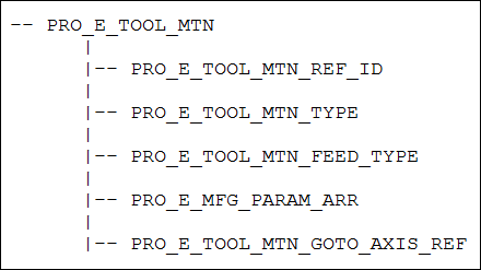
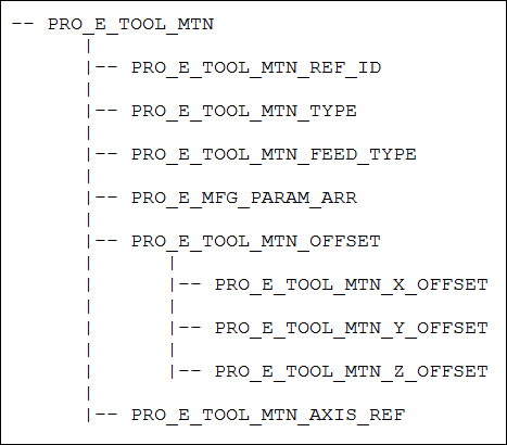
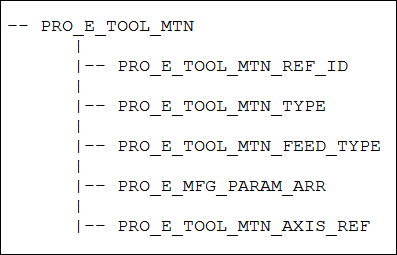
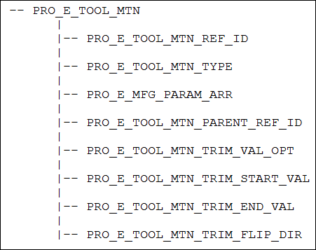
The following table lists the contents of PRO_E_TOOL_MTN element.
Element ID
Data Type
Description
PRO_E_FEATURE_TYPE
PRO_VALUE_TYPE_INT
Mandatory element. Specifies the type of the feature . The valid values for this element are:
•  PRO_FEAT_MILL— For milling manual cycle.
•  PRO_FEAT_TURN— For turning manual cycle.
PRO_E_STD_FEATURE_NAME
PRO_VALUE_TYPE_WSTRING
Optional element. Specifies the name for the Creo NC sequence. The default value is Manual_Cycle_1.
PRO_E_NCSEQ_TYPE
PRO_VALUE_TYPE_INT
Mandatory element. Specifies the type of Creo NC sequence. The valid values for this element are:
•  PRO_SEQ_MANUAL_CYCLE_MILL— For milling manual cycle.
•  PRO_SEQ_MANUAL_CYCLE_TURN— For turning manual cycle.
PRO_E_MFG_OPER_REF
PRO_VALUE_TYPE_SELECTION
Mandatory element. Specifies the operation feature selection.
PRO_E_Creo NC SEQ_CSYS
PRO_VALUE_TYPE_SELECTION
Mandatory element. Specifies the datum coordinate system that will be used as the coordinate system for the Creo NC sequence.
PRO_E_RETR_SURF
Compound
This compound element specifies retract definition. For more information, refer to the section Retract Elements
Note
This element is mandatory for milling manual Creo NC sequences and is ignored for turning manual sequences.
.
PRO_E_MFG_SUB_SPINDLE_OPT
PRO_VALUE_TYPE_INT
Optional Element. Specifies the type of spindle assigned to the sequence. This element can be used when two parts are machined during the same operation in different spindles, that is in the main spindle and in the sub spindle. The valid values for this element are defined by the enumerated type ProSubSpindleOpt. For more information on the values of ProSubSpindleOpt, refer to the section Spindle Types
PRO_E_MFG_TOOL_REF_COMPOUND
Compound
Mandatory compound element. Specifies tool reference definition. For more information, refer to the section Tool Reference.
PRO_E_MFG_TOOL_ADAPTER_NAME
PRO_VALUE_TYPE_WSTRING
Optional element. Specifies the tool adapter model name.
Note
This element is optional for milling manual sequences and is ignored for turning manual sequences.
PRO_E_MFG_PARAM_SITE_NAME
PRO_VALUE_TYPE_WSTRING
Optional element. Specifies the name of the site file with default values for manufacturing parameters.
Note
The site file name will be ignored if the site does not exist in the manufacturing model.
PRO_E_MFG_PARAM_ARR
Array
Mandatory element. Defines an array of manufacturing parameters. For more information, refer to the section Manufacturing Parameters.
PRO_E_TOOL_MTN_ARR
Array
Mandatory element. Specifies an array of tool motions.
PRO_E_TOOL_MTN
Compound
Mandatory compound element. Specifies the tool motion compound specifications. The applicable tool motion types for this element are:
•  PRO_TM_TYPE_FOLLOW_CURVE. For more information, refer to the section Tool Motion — Follow Curve.
•  PRO_TM_TYPE_GOTO
_POINT
. For more information, refer to the section Tool Motion — Go To Point.
•  PRO_TM_TYPE_GO_DELTA. For more information, refer to the section Tool Motion — Go Delta.
•  PRO_TM_TYPE_GOTO_SURFACE— This tool motion type is for milling manual cycle only. For more information, refer to the section Tool Motion — Go To Surface.
•  PRO_TM_TYPE_GOTO_AXIS
— This tool motion type is for milling manual cycle only. For more information, refer to the section Tool Motion — Go To Axis.
•  PRO_TM_TYPE_GOHOME. For more information, refer to the section Tool Motion Go Home.
•  PRO_TM_TYPE_CONNECT. For more information, refer to the section Tool Motion — Go Home.
•  PRO_TM_TYPE_PLUNGE— This tool motion type is for milling manual cycle only. For more information, refer to the section Tool Motion — Plunge.
•  PRO_TM_TYPE_GO_RETRACT— This tool motion type is for milling manual cycle only. For more information, refer to the section Tool Motion — Plunge.
•  PRO_TM_TYPE_CL_COMMAND. For more information, refer to the section Tool Motion — CL Command.
The elements related to tool motion are defined in ProMfgElemToolMtnAutoCut.h. For more information, refer to the section Tool Motion — Auto Cut .
PRO_E_MFG_START_PNT
PRO_VALUE_TYPE_SELECTION
Optional element. Specifies the datum point selection. It allows to start the machining at the specified position.
PRO_E_MFG_END_PNT
PRO_VALUE_TYPE_SELECTION
Optional element. Specifies the datum point selection. It allows to end the machining at the specified position.
PRO_E_MFG_PREREQUISITE_ARR
Array
Optional element. This array specifies the Ids of the prerequisite sequences. For more information, refer to the section Sequence Prerequisites.
PRO_E_MFG_PROCESS_REF
PRO_VALUE_TYPE_SELECTION
Optional element. Specifies the reference selections such as part, feature, curve, surface, datum plane, axis, point, and datum coordinate. It allows you to create additional geometric references to be used only in special process application. This element supports multiple selections.
PRO_E_MFG_FEAT_VIEW_NAME
PRO_VALUE_TYPE_WSTRING
Optional element. Specifies the name of the view. This element allows you to associate a specific view with the machining step.
Note
This element is used only in special process application.
PRO_E_MFG_SIMP_REP_NAME
PRO_VALUE_TYPE_WSTRING
Optional element. Specifies the simplified representation name. This element allows you to associate the specific simplified representation with the machining step.
Note
This element is used only in special process application.
PRO_E_MFG_TIME_ESTIMATE
PRO_VALUE_TYPE_DOUBLE
Optional element. Specifies the time estimated for the machining step.
Note
This element is used only in special process application.
PRO_E_MFG_COST_ESTIMATE
PRO_VALUE_TYPE_DOUBLE
Optional element. Specifies the cost estimate for the machining step.
Note
This element is used only in special process application.
PRO_E_MFG_TIME_ACTUAL
PRO_VALUE_TYPE_DOUBLE
Optional element. Specifies the actual time for the machining step.
Note
This element is used only in special process application.
PRO_E_MFG_COMMENTS
PRO_VALUE_TYPE_WSTRING
Specifies the sequence comments.
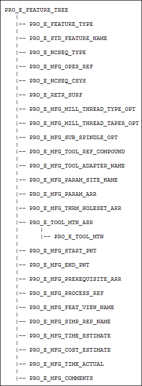
Element Trees: Thread Milling
This section describes how to construct and access the element tree for a thread roughing feature. It also describes how to create, redefine, and access the properties of these features.
The Thread Milling Feature Element Tree:
The element tree for the thread milling Creo NC sequence is documented in the header file ProMfgFeatThreadMilling.h, and is as shown in the following figure:
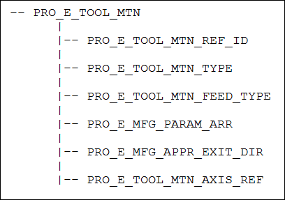
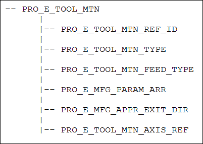
Element tree for PRO_E_TOOL_MTN element
Image
Element ID
Data Type
Description
PRO_E_FEATURE_TYPE
PRO_VALUE_TYPE_INT
Mandatory element. Specifies the type of the feature. The valid value for this element is PRO_FEAT_MILL.
PRO_E_STD_FEATURE_NAME
PRO_VALUE_TYPE_WSTRING
Optional element. Specifies the name for the Creo NC sequence. The default value is Thread_Milling_1.
PRO_E_NCSEQ_TYPE
PRO_VALUE_TYPE_INT
Mandatory element. Specifies the type of Creo NC sequence. The valid value for this element is PRO_NCSEQ_THREAD_MILL.
PRO_E_MFG_OPER_REF
PRO_VALUE_TYPE_SELECTION
Mandatory element. Specifies the operation feature selection.
PRO_E_NCSEQ_CSYS
PRO_VALUE_TYPE_SELECTION
Mandatory element. Specifies the datum coordinate system that will be used as the coordinate system for the Creo NC sequence.
PRO_E_RETR_SURF
Compound
Mandatory compound element. Specifies retract definition. For more information, refer to the section Retract Elements.
Note
This element is mandatory when PRO_E_DRILL_MODE is set to PRO_DRILL_HOLE_ON_MILL and is ignored when set to PRO_DRILL_HOLE_ON_LATHE.
PRO_E_MFG_MILL_THREAD_TYPE_OPT
PRO_VALUE_TYPE_INT
Mandatory element. Specifies the thread type. The valid values for this element are:
•  External
•  Internal
The value for this element is defined by the ProMillThreadTypeparameter.
PRO_E_MFG_MILL_THREAD_TAPER_OPT
PRO_VALUE_TYPE_INT
Mandatory element. Specifies the taper type. The valid values for this element are:
•  None
•  NTP
•  Custom
The value for this element is defined by the ProMillThreadTaperType parameter.
PRO_E_MFG_SUB_SPINDLE_OPT
PRO_VALUE_TYPE_INT
Optional Element. Specifies the type of spindle assigned to the sequence. This element can be used when two parts are machined during the same operation in different spindles, that is in the main spindle and in the sub spindle. The valid values for this element are defined by the enumerated type ProSubSpindleOpt. For more information on the values of ProSubSpindleOpt, refer to the section Spindle Types
PRO_E_MFG_TOOL_REF_COMPOUND
Compound
Mandatory compound element. Specifies tool reference definition. For more information, refer to the section Tool Reference .
PRO_E_MFG_TOOL_ADAPTER_NAME
PRO_VALUE_TYPE_WSTRING
Optional element. Specifies the tool adapter model name.
PRO_E_MFG_PARAM_SITE_NAME
PRO_VALUE_TYPE_WSTRING
Optional element. Specifies the name of the site file with default values for manufacturing parameters.
Note
The site file name will be ignored if the site does not exist in the manufacturing model.
PRO_E_MFG_PARAM_ARR
Array
Mandatory element. Defines an array of manufacturing parameters. For more information, refer to the section Manufacturing Parameters.
PRO_E_MFG_THRM_HOLESET_ARR
Array
Specifies an array of thread holesets. It gives specification of threads to machine. For more information, refer to the section Manufacturing Thread Milling Holeset.
PRO_E_TOOL_MTN_ARR
Array
Mandatory element. Specifies an array of tool motions.
PRO_E_TOOL_MTN
Compound
Mandatory compound element. Specifies the tool motion compound specifications. The applicable tool motion types for this element are:
•  PRO_TM_TYPE_THREAD
_MILLING
. For more information, refer to the section Tool Motion — Thread Milling.
•  PRO_TM_TYPE_FOLLOW_CUT. For more information, refer to the section Tool Motion — Follow Cut.
•  PRO_TM_TYPE_GOTO_
POINT
. For more information, refer to the section Tool Motion — Go To Point.
•  PRO_TM_TYPE_GO_DELTA. For more information, refer to the section Tool Motion — Go Delta.
•  PRO_TM_TYPE_GOHOME. For more information, refer to the section Tool Motion — Go Home.
•  PRO_TM_TYPE_CONNECT. For more information, refer to the section Tool Motion — Connect.
•  PRO_TM_TYPE_PLUNGE. For more information, refer to the section Tool Motion — Plunge.
•  PRO_TM_TYPE_GO_RETRACT. For more information, refer to the section Tool Motion — Go Retract.
•  PRO_TM_TYPE_TANGENT_APPROACH. For more information, refer to the section Tool Motion — Tangent Approach.
•  PRO_TM_TYPE_TANGENT_EXIT. For more information, refer to the section Tool Motion — Tangent Exit.
•  PRO_TM_TYPE_NORMAL_APPROACH. For more information, refer to the section Tool Motion — Normal Approach.
•  PRO_TM_TYPE_NORMAL_EXIT. For more information, refer to the section Tool Motion — Normal Exit.
•  PRO_TM_TYPE_LEAD_IN. For more information, refer to the section Tool Motion — Lead In.
•  PRO_TM_TYPE_LEAD_OUT. For more information, refer to the section Tool Motion — Lead Out.
•  PRO_TM_TYPE_RAMP_APPROACH. For more information, refer to the section Tool Motion — Ramp Approach.
•  PRO_TM_TYPE_RAMP_EXIT. For more information, refer to the section Tool Motion — Ramp Exit.
•  PRO_TM_TYPE_CL_COMMAND. For more information, refer to the section Tool Motion — CL Command. For more information, refer to the section Tool Motion — Auto Cut.
PRO_E_MFG_START_PNT
PRO_VALUE_TYPE_SELECTION
Optional element. Specifies the datum point selection. It allows to start the machining at the specified position.
PRO_E_MFG_END_PNT
PRO_VALUE_TYPE_SELECTION
Optional element. Specifies the datum point selection. It allows to end the machining at the specified position.
PRO_E_MFG_PREREQUISITE_ARR
Array
Optional element. This array specifies the Ids of the prerequisite sequences. For more information, refer to the section Sequence Prerequisites.
PRO_E_MFG_PROCESS_REF
PRO_VALUE_TYPE_SELECTION
Optional element. Specifies the reference selections such as part, feature, curve, surface, datum plane, axis, point, and datum coordinate. It allows you to create additional geometric references to be used only in special process application. This element supports multiple selections.
PRO_E_MFG_FEAT_VIEW_NAME
PRO_VALUE_TYPE_WSTRING
Optional element. Specifies the name of the view. This element allows you to associate a specific view with the machining step.
Note
This element is used only in special process application.
PRO_E_MFG_SIMP_REP_NAME
PRO_VALUE_TYPE_WSTRING
Optional element. Specifies the simplified representation name. This element allows you to associate the specific simplified representation with the machining step.
Note
This element is used only in special process application.
PRO_E_MFG_TIME_ESTIMATE
PRO_VALUE_TYPE_DOUBLE
Optional element. Specifies the time estimated for the machining step.
Note
This element is used only in special process application.
PRO_E_MFG_COST_ESTIMATE
PRO_VALUE_TYPE_DOUBLE
Optional element. Specifies the cost estimate for the machining step.
Note
This element is used only in special process application.
PRO_E_MFG_TIME_ACTUAL
PRO_VALUE_TYPE_DOUBLE
Optional element. Specifies the actual time for the machining step.
Note
This element is used only in special process application.
PRO_E_MFG_COMMENTS
PRO_VALUE_TYPE_WSTRING
Specifies the sequence comments.
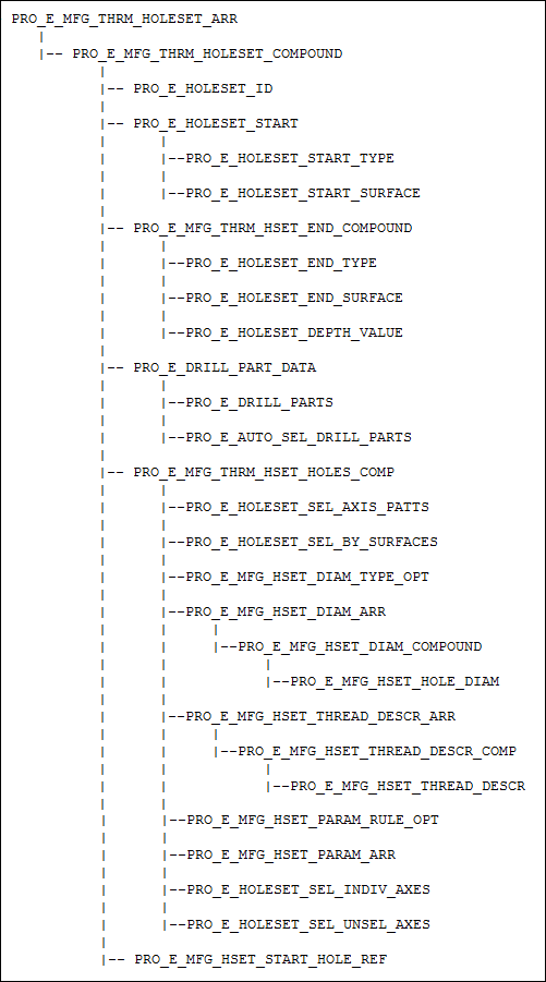
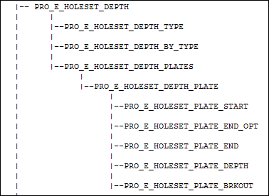
Manufacturing Thread Milling Holeset
The element PRO_E_MFG_THRM_HOLESET_ARR is documented in the header file ProMfgElemThreadHoleset.h, and is shown in the following figure.
Element tree for Manufacturing Thread Milling Holeset
Image
The following table lists the contents of PRO_E_MFG_THRM_HOLESET_ARR element.
Element ID
Data Type
Description
PRO_E_MFG_THRM_HOLESET_ARR
Array
This element specifies an array of thread holesets. It gives specifications about machining references.
PRO_E_MFG_THRM_HOLESET_COMPOUND
Compound
Mandatory element. This compound element specifies the thread holeset definition.
Note
Specify this element only when the holeset array has at least one member
PRO_E_HOLESET_TYPE
PRO_VALUE_TYPE_INT
Mandatory element. Specifies the holeset type. The valid value for this element is PRO_HOLESET_DRILL_AXES.
PRO_E_HOLESET_START
Compound
Mandatory element. Specifies the holemaking start compound specification.
PRO_E_HOLESET_START_TYPE
PRO_VALUE_TYPE_INT
Mandatory element. Specifies the start surface option using the enumerated value ProDrillStartType.
PRO_E_HOLESET_START_SURFACE
PRO_VALUE_TYPE_SELECTION
Specifies the starting surface or quilt selection.
Note
This element is mandatory if the element PRO_E_HOLESET_START_TYPE is set to PRO_DRILL_FROM_SURFACE.
PRO_E_MFG_THRM_HSET_END_COMPOUND
Compound
Mandatory element. Specifies the thread depth compound specification.
PRO_E_HOLESET_END_TYPE
PRO_VALUE_TYPE_INT
Mandatory element. Specifies the end type option. The valid values for this element are:
•  PRO_DRILL_UPTO_SURFACE
•  PRO_DRILL_AUTO_END
•  PRO_DRILL_OFFSET_FROM_START
PRO_E_HOLESET_END_SURFACE
PRO_VALUE_TYPE_SELECTION
Specifies the end surface or quilt selection.
Note
This element is mandatory if the element PRO_E_HOLESET_END_TYPE is set to PRO_DRILL_UPTO_SURFACE.
PRO_E_HOLESET_DEPTH_VALUE
PRO_VALUE_TYPE_DOUBLE
Specifies the depth to the cut thread from the start.
Note
This element is mandatory if the element PRO_E_HOLESET_END_TYPE is set to PRO_DRILL_OFFSET_FROM_START.
PRO_E_DRILL_PART_DATA
Compound
This element gives compound information about components used in depth computation.
Note
Specify this element only if the start or end of machining has to be computed and the following conditions hold true:
•  The element PRO_E_HOLESET_START_TYPE is set to PRO_DRILL_AUTO_START.
•  The element PRO_E_HOLESET_END_TYPE is set to PRO_DRILL_AUTO or PRO_DRILL_THRU_ALL
•  The element PRO_E_HOLESET_DEPTH_TYPE is set to PRO_DRILL_AUTO or PRO_DRILL_THRU_ALL
PRO_E_AUTO_SEL_DRILL_PARTS
PRO_VALUE_TYPE_INT
Mandatory element. This element defines the way in which components are collected. The valid values for this element are:
•  TRUE— All components of type reference part or workpiece are considered for depth calculation.
•  FALSE—Only selected components are considered in depth calculation.
PRO_E_DRILL_PARTS
PRO_VALUE_TYPE_SELECTION
Specifies the components selections. This element supports multiple selections.
Note
•  This element is mandatory if the element PRO_E_AUTO_SEL_DRILL_PARTS is set to FALSE.
•  This element is ignored if the element PRO_E_AUTO_SEL_DRILL_PARTS is set to FALSE.
PRO_E_MFG_THRM_HSET_HOLES_COMP
Compound
Mandatory element. This compound element gives the compound information about location of holes.
Note
Specify this element only when at least one of the following have been defined:
•  PRO_E_HOLESET_SEL_INDIV_AXES
•  PRO_E_HOLESET_SEL_AXIS_PATTS
•  PRO_E_HOLESET_SEL_BY_SURFACES
•  PRO_E_MFG_HSET_DIAM_TYPE_OPT
•  PRO_E_MFG_HSET_THREAD_DESCR_ARR
•  PRO_E_MFG_HSET_DIAM_ARR
•  PRO_E_MFG_HSET_PARAM_ARR
PRO_E_HOLESET_SEL_AXIS_PATTS
PRO_VALUE_TYPE_SELECTION
Optional element. Specifies the selection of axes of patterned holes. This element supports multiple selections.
Note
If a pattern leader is selected, all holes in pattern will be collected.
PRO_E_HOLESET_SEL_BY_SURFACES
PRO_VALUE_TYPE_SELECTION
Optional element. Specifies the selection of surfaces or quilts with holes. This element supports multiple selections.
PRO_E_MFG_HSET_DIAM_TYPE_OPT
PRO_VALUE_TYPE_INT
Optional element. Specifies the type of hole diameters that can be collected in the element PRO_E_MFG_HSET_DIAM_ARR. The type of hole diameter is specified using the enumerated data type ProHolesetDiamType. The valid values are:
•  PRO_HSET_ALL_DIAMS—This is the default value. Specifies that diameters of both solid surfaces and cosmetic threads can be collected.
Note
If the element PRO_E_MFG_HSET_DIAM_TYPE_OPT is not defined, then by default, the hole diameter of type PRO_HSET_ALL_DIAMS is used.
•  PRO_HSET_HOLE_DIAMS—Specifies that diameters only of solid surfaces can be collected.
•  PRO_HSET_THREAD_DIAMS—Specifies that diameters only of cosmetic threads can be collected.
PRO_E_MFG_HSET_DIAM_ARR
Array
Optional element. Specifies an array of diameters of holes to machine.
PRO_E_MFG_HSET_DIAM_COMPOUND
Compound
Optional element. Specifies the compound definition of a hole diameter.
PRO_E_MFG_HSET_HOLE_DIAM
PRO_VALUE_TYPE_DOUBLE
Specifies the diameter of a hole to machine.
Note
This element is a mandatory child element of the element PRO_E_MFG_HSET_DIAM_COMPOUND.
PRO_E_MFG_HSET_THREAD_DESCR_ARR
Array
Optional element. This array element gives thread descriptions of holes to machine.
PRO_E_MFG_HSET_THREAD_DESCR_COMP
Compound
Optional element. Specifies compound definition of a thread description.
PRO_E_MFG_HSET_THREAD_DESCR
PRO_VALUE_TYPE_WSTRING
Specifies the thread size string.
Note
This element is a mandatory child of PRO_E_MFG_HSET_THREAD_DESCR_COMP element.
PRO_E_MFG_HSET_PARAM_RULE_OPT
PRO_VALUE_TYPE_INT
Specifies the type of query that must be used to search for holes to machine.
The query type is specified using the enumerated data type ProHsetParamRuleOpt. The valid values are:
•  PRO_HSET_BOOL_OPER_OR—Collects holes that satisfy at least one of the search conditions set for a parameter.
PRO_HSET_BOOL_OPER_AND—Collects holes that satisfy all the search conditions set for a parameter.
The search conditions and parameters are defined in the elements PRO_E_MFG_HSET_PARAM*.
PRO_E_MFG_HSET_PARAM_ARR
Array
Optional element. Specifies an array of search conditions to collect holes for machining.
PRO_E_MFG_HSET_PARAM_COMPOUND
Compound
Optional element. Specifies a compound element that defines a search condition to match with the user defined parameters in hole features.
Each condition defines an expression with user defined parameter name on the left side of the expression and value to compare on the right side.
PRO_E_MFG_HSET_PARAM_NAME
PRO_VALUE_TYPE_WSTRING
Specifies the name of the user defined parameter.
Note
This element is a mandatory child of PRO_E_MFG_HSET_PARAM_COMPOUND element.
PRO_E_MFG_HSET_PARAM_DTYPE
PRO_VALUE_TYPE_INT
Specifies the data type of the values using the enumerated value ProParamvalueType.
Note
This element is a mandatory child of PRO_E_MFG_HSET_PARAM_COMPOUND element.
PRO_E_MFG_HSET_PARAM_OPER
PRO_VALUE_TYPE_INT
Specifies the type of expression operator using the enumerated value ProDrillParamOper.
Note
This element is a mandatory child of PRO_E_MFG_HSET_PARAM_COMPOUND element.
PRO_E_MFG_HSET_PARAM_VAL_DBL
PRO_VALUE_TYPE_DOUBLE
Specifies the value of the double data type.
Note
•  This element is mandatory child of PRO_E_MFG_HSET_PARAM_COMPOUND element for double data type (PRO_E_MFG_HSET_PARAM_DTYPE is set to PRO_PARAM_DOUBLE). It is ignored for other data types.
PRO_E_MFG_HSET_PARAM_VAL_INT
PRO_VALUE_TYPE_INT
Specifies the value of the integer data type.
Note
•  This element is mandatory child of PRO_E_MFG_HSET_PARAM_COMPOUND element for integer data type (PRO_E_MFG_HSET_PARAM_DTYPE is set to PRO_PARAM_INTEGER). It is ignored for other data types.
PRO_E_MFG_HSET_PARAM_VAL_STR
PRO_VALUE_TYPE_WSTRING
Specifies the value of the string data type.
Note
•  This element is mandatory child of PRO_E_MFG_HSET_PARAM_COMPOUND element for string data type (PRO_E_MFG_HSET_PARAM_DTYPE is set to PRO_PARAM_STRING). It is ignored for other data types.
PRO_E_MFG_HSET_PARAM_VAL_BOOL
PRO_VALUE_TYPE_INT
Specifies the value of the string data type.
Note
•  This element is mandatory child of PRO_E_MFG_HSET_PARAM_COMPOUND element for boolean data type (PRO_E_MFG_HSET_PARAM_DTYPE is set to PRO_PARAM_BOOLEAN). It is ignored for other data types.
PRO_E_HOLESET_SEL_INDIV_AXES
PRO_VALUE_TYPE_SELECTION
Specifies the selection of datum axes. This element supports multiple selections.
Note
This element is mandatory if you have not defined the following elements:
•  PRO_E_HOLESET_SEL_AXIS_PATTS
•  PRO_E_HOLESET_SEL_BY_SURFACES
•  PRO_E_MFG_HSET_THREAD_DESCR_ARR
•  PRO_E_MFG_HSET_DIAM_ARR
•  PRO_E_MFG_HSET_PARAM_ARR
PRO_E_HOLESET_SEL_UNSEL_AXES
PRO_VALUE_TYPE_SELECTION
Optional element. Specifies the selection of axes of holes to be excluded for machining. This element supports multiple selections.
PRO_E_MFG_HSET_START_HOLE_REF
PRO_VALUE_TYPE_SELECTION
Optional element. Specifies the axis selection for the hole to be machined first.
Element Trees: Turning Step
This section describes how to construct and access the element tree for a turning step. It also describes how to create, redefine, and access the properties of these features. Refer to the Creo NC Help for more information on the Turn type Creo NC sequences.
The Turning Element Tree:
The element tree for the turning step is documented in the header file ProMfgFeatTurning.h, and is as shown in the following figure:
Element Tree for Turning feature
Image
The following table describes the elements in the element tree for the area turning feature.
Element ID
Data Type
Description
PRO_E_FEATURE_TYPE
PRO_VALUE_TYPE_INT
Mandatory element. Specifies the type of the feature. The valid value for this element is PRO_FEAT_TURN.
PRO_E_STD_FEATURE_NAME
PRO_VALUE_TYPE_WSTRING
Optional element. Specifies the name for the Creo NC sequence. The default values for this element are:
•  Area_Turning_2—For area turning Creo NC sequences.
•  Profile_Turning_1—For profile turning Creo NC sequences.
•  Groove_Turning_1—For groove turning Creo NC sequences.
PRO_E_SEQ_TYPE
PRO_VALUE_TYPE_INT
Mandatory element. Specifies the type of Creo NC sequence. The valid values for this element are:
•  PRO_SEQ_AREA_TURN—For an area turning sequence.
•  PRO_SEQ_GROOVE_TURN—For a groove turning sequence.
•  PRO_SEQ_PROF_TURN—For a profile turning sequence.
PRO_E_MFG_OPER_REF
PRO_VALUE_TYPE_SELECTION
Mandatory element. Specifies the operation feature selection.
PRO_E_SEQ_CSYS
PRO_VALUE_TYPE_SELECTION
Mandatory element. Specifies the datum coordinate system that will be used as the coordinate system for the Creo NC sequence.
PRO_E_MFG_SUB_SPINDLE_OPT
PRO_VALUE_TYPE_INT
Optional Element. Specifies the type of spindle assigned to the Creo NC sequence. This element can be used when two parts are machined during the same operation in different spindles, that is in the main spindle and in the sub spindle. The valid values for this element are defined by the enumerated type ProSubSpindleOpt. For more information on the values of ProSubSpindleOpt, refer to the section Spindle Types
PRO_E_MFG_TOOL_REF_COMPOUND
Compound
Mandatory compound element. Specifies retract definition. For more information, refer to the section Retract Elements.
PRO_E_MFG_PARAM_SITE_NAME
PRO_VALUE_TYPE_WSTRING
Optional element. Specifies the name of the site file with default values for manufacturing parameters.
Note
The site file name will be ignored if the site does not exist in the manufacturing model.
PRO_E_MFG_PARAM_ARR
Array
Mandatory element. Defines an array of manufacturing parameters. For more information, refer to the section Manufacturing Parameters.
PRO_E_TOOL_MTN_ARR
Array
Mandatory element. Specifies an array of tool motions.
PRO_E_TOOL_MTN
Compound
Mandatory compound element. Specifies the tool motion compound specifications. The applicable tool motion types for this element are:
•  PRO_TM_TYPE_AREA_TURNING. For more information, refer to the section Tool Motion — Area and Groove Turning.
•  PRO_TM_TYPE_GROOVE_TURNING. For more information, refer to the section Tool Motion — Area and Groove Turning.
•  PRO_TM_TYPE_PROF_TURNING. For more information, refer to the section Tool Motion — Profile Turning.
•  PRO_TM_TYPE_FOLLOW_CUT. For more information, refer to the section Tool Motion — Follow Cut
PRO_TM_TYPE_FOLLOW_CURVE. For more information, refer to the section Tool Motion — Follow Curve.
•  PRO_TM_TYPE_GOTO_POINT. For more information, refer to the section Tool Motion — Go To Point
•  PRO_TM_TYPE_GO_DELTA. For more information, refer to the section Tool Motion — Go Delta.
•  PRO_TM_TYPE_GOHOME. For more information, refer to the section Tool Motion — Go Home.
•  PRO_TM_TYPE_TANGENT_APPROACH. For more information, refer to the section Tool Motion — Tangent Approach.
•  PRO_TM_TYPE_TANGENT_EXIT. For more information, refer to the section Tool Motion — Tangent Exit.
•  PRO_TM_TYPE_NORMAL_APPROACH. For more information, refer to the section Tool Motion — Normal Approach.
•  PRO_TM_TYPE_NORMAL_EXIT. For more information, refer to the section Tool Motion — Normal Exit
•  PRO_TM_TYPE_LEAD_IN. For more information, refer to the section Tool Motion — Lead In.
•  PRO_TM_TYPE_LEAD_OUT. For more information, refer to the section Tool Motion — Lead Out.
•  PRO_TM_TYPE_RAMP_APPROACH. For more information, refer to the section Tool Motion — Ramp Approach.
•  PRO_TM_TYPE_RAMP_EXIT. For more information, refer to the section Tool Motion — Ramp Exit.
•  PRO_TM_TYPE_CONNECT. For more information, refer to the section Tool Motion — Connect
•  PRO_TM_TYPE_CL_COMMAND. For more information, refer to the section Tool Motion — CL Command.
For more information, refer to the section Tool Motion — Auto Cut.
PRO_E_MFG_START_PNT
PRO_VALUE_TYPE_SELECTION
Optional element. Specifies the datum point selection. It allows to start the machining at the specified position.
PRO_E_MFG_END_PNT
PRO_VALUE_TYPE_SELECTION
Optional element. Specifies the datum point selection. It allows to end the machining at the specified position.
PRO_E_MFG_PREREQUISITE_ARR
Array
Optional element. This array specifies the Ids of the prerequisiteCreo NC sequences. For more information, refer to the section Sequence Prerequisites.
PRO_E_MFG_PROCESS_REF
PRO_VALUE_TYPE_SELECTION
Optional element. Specifies the reference selections such as part, feature, curve, surface, datum plane, axis, point, and datum coordinate. It allows you to create additional geometric references to be used only in special process application. This element supports multiple selections.
PRO_E_MFG_FEAT_VIEW_NAME
PRO_VALUE_TYPE_WSTRING
Optional element. Specifies the name of the view. This element allows you to associate a specific view with the machining step.
Note
This element is used only in special process application.
PRO_E_MFG_SIMP_REP_NAME
PRO_VALUE_TYPE_WSTRING
Optional element. Specifies the simplified representation name. This element allows you to associate the specific simplified representation with the machining step.
Note
This element is used only in special process application.
PRO_E_MFG_TIME_ESTIMATE
PRO_VALUE_TYPE_DOUBLE
Optional element. Specifies the time estimated for the machining step.
Note
This element is used only in special process application.
PRO_E_MFG_COST_ESTIMATE
PRO_VALUE_TYPE_DOUBLE
Optional element. Specifies the cost estimate for the machining step.
Note
This element is used only in special process application.
PRO_E_MFG_TIME_ACTUAL
PRO_VALUE_TYPE_DOUBLE
Optional element. Specifies the actual time for the machining step.
Note
This element is used only in special process application.
PRO_E_MFG_COMMENTS
PRO_VALUE_TYPE_WSTRING
Specifies the sequence comments.
Element Trees: Thread Turning Step
This section describes how to construct and access the element tree for a thread turning step. It also describes how to create, redefine, and access the properties of these features.
The Thread Turning Element Tree:
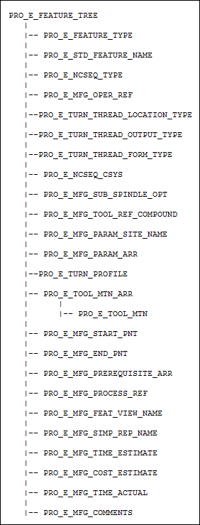
The element tree for the thread turning Creo NCsequence is documented in the header file ProMfgFeatTurnThread.h, and is as shown in the following figure:
Element Tree for Thread Turning feature
Image
Element ID
Data Type
Description
PRO_E_FEATURE_TYPE
PRO_VALUE_TYPE_INT
Mandatory element. Specifies the type of the feature. The valid value for this element is PRO_FEAT_TURN.
PRO_E_STD_FEATURE_NAME
PRO_VALUE_TYPE_WSTRING
Optional element. Specifies the name for the Creo NC sequence. The default value for this element is Thread_Turning_1.
PRO_E_SEQ_TYPE
PRO_VALUE_TYPE_INT
Mandatory element. Specifies the type of Creo NC sequence. The valid value for this element is PRO_SEQ_THREAD_TURN
PRO_E_MFG_OPER_REF
PRO_VALUE_TYPE_SELECTION
Mandatory element. Specifies the operation feature selection.
PRO_E_TURN_THREAD_LOCATION_TYPE
PRO_VALUE_TYPE_INT
Mandatory element. Specifies the location of the thread. The valid values for this element are:
•  PRO_E_TURN_OPTION_OUT—For external threads
•  PRO_E_TURN_OPTION_IN—For internal threads
PRO_E_TURN_THREAD_OUTPUT_TYPE
PRO_VALUE_TYPE_INT
Mandatory element. Specifies the type of output You can specify one of the following valid values for this element:
•  PRO_E_TURN_THREAD_ISO
•  PRO_E_TURN_THREAD_AI_MACRO
PRO_E_TURN_THREAD_FORM_TYPE
PRO_VALUE_TYPE_INT
Mandatory element. Specifies the type of the thread. . The valid values for this element are:
•  PRO_E_TURN_THREAD_UNIFIED—For Unified threads
•  PRO_E_TURN_THREAD_GENERAL—For General threads
•  PRO_E_TURN_THREAD_BUTTRESS—For Buttress threads
•  PRO_E_TURN_THREAD_ACME—For Acme threads
PRO_E_SEQ_CSYS
PRO_VALUE_TYPE_SELECTION
Mandatory element. Specifies the datum coordinate system that will be used as the coordinate system for the Creo NC sequence.
PRO_E_MFG_SUB_SPINDLE_OPT
PRO_VALUE_TYPE_INT
Optional Element. Specifies the type of spindle assigned to the sequence. This element can be used when two parts are machined during the same operation in different spindles, that is in the main spindle and in the sub spindle. The valid values for this element are defined by the enumerated type ProSubSpindleOpt. For more information on the values of ProSubSpindleOpt, refer to the section Spindle Types
PRO_E_MFG_TOOL_REF_COMPOUND
Compound
Mandatory compound element. Specifies retract definition. For more information, refer to the section Retract Elements .
PRO_E_MFG_PARAM_SITE_NAME
PRO_VALUE_TYPE_WSTRING
Optional element. Specifies the name of the site file with default values for manufacturing parameters.
Note
The site file name will be ignored if the site does not exist in the manufacturing model.
PRO_E_MFG_PARAM_ARR
Array
Mandatory element. Defines an array of manufacturing parameters. For more information, refer to the section Manufacturing Parameters.
PRO_E_TURN_PROFILE
PRO_VALUE_TYPE_SELECTION
Mandatory element. Specifies turn profile selection.
PRO_E_TOOL_MTN_ARR
Array
Mandatory element. Specifies an array of tool motions.
PRO_E_TOOL_MTN
Compound
Mandatory compound element. Specifies the tool motion compound specifications. For more information, refer to the section Tool Motion — Auto Cut.
PRO_E_MFG_START_PNT
PRO_VALUE_TYPE_SELECTION
Optional element. Specifies the datum point selection. It allows to start the machining at the specified position.
PRO_E_MFG_END_PNT
PRO_VALUE_TYPE_SELECTION
Optional element. Specifies the datum point selection. It allows to end the machining at the specified position.
PRO_E_MFG_PREREQUISITE_ARR
Array
Optional element. This array specifies the Ids of the prerequisite sequences. For more information, refer to the section Sequence Prerequisites.
PRO_E_MFG_PROCESS_REF
PRO_VALUE_TYPE_SELECTION
Optional element. Specifies the reference selections such as part, feature, curve, surface, datum plane, axis, point, and datum coordinate. It allows you to create additional geometric references to be used only in special process application. This element supports multiple selections.
PRO_E_MFG_FEAT_VIEW_NAME
PRO_VALUE_TYPE_WSTRING
Optional element. Specifies the name of the view. This element allows you to associate a specific view with the machining step.
Note
This element is used only in special process application.
PRO_E_MFG_SIMP_REP_NAME
PRO_VALUE_TYPE_WSTRING
Optional element. Specifies the simplified representation name. This element allows you to associate the specific simplified representation with the machining step.
Note
This element is used only in special process application.
PRO_E_MFG_TIME_ESTIMATE
PRO_VALUE_TYPE_DOUBLE
Optional element. Specifies the time estimated for the machining step.
Note
This element is used only in special process application.
PRO_E_MFG_COST_ESTIMATE
PRO_VALUE_TYPE_DOUBLE
Optional element. Specifies the cost estimate for the machining step.
Note
This element is used only in special process application.
PRO_E_MFG_TIME_ACTUAL
PRO_VALUE_TYPE_DOUBLE
Optional element. Specifies the actual time for the machining step.
Note
This element is used only in special process application.
PRO_E_MFG_COMMENTS
PRO_VALUE_TYPE_WSTRING
Specifies the sequence comments
Element Trees: Creo NC Operation Definition
This section describes how to construct and access the element tree for a Creo NC operation definition feature. It also describes how to create, redefine, and access the properties of these features.
The Creo NC Operation Definition Element Tree:
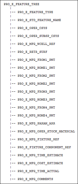
The element tree for the Creo NC operation sequence is documented in the header file ProMfgFeatOperation.h, and is as shown in the following figure:
Element Tree for Creo NC operation definition feature
Image
Element ID
Data Type
Description
PRO_E_FEATURE_TYPE
PRO_VALUE_TYPE_INT
Mandatory element. Specifies the type of the feature. The valid value for this element is PRO_FEAT_OPERATION.
PRO_E_STD_FEATURE_NAME
PRO_VALUE_TYPE_WSTRING
Optional element. Specifies the name for the Creo NC sequence. The default value for this element is OP040.
PRO_E_OPER_CSYS
PRO_VALUE_TYPE_SELECTION
Mandatory element. Specifies the datum coordinate system that will be used as the operation coordinate system for the Creo NC sequence.
PRO_E_OPER_SUBSP_CSYS
PRO_VALUE_TYPE_SELECTION
Optional element. Select a coordinate system geometry item which can be used as a sub-spindle coordinate system.
PRO_E_MFG_WCELL_REF
PRO_VALUE_TYPE_SELECTION
Mandatory element. Specifies the workcell feature selection.
PRO_E_RETR_SURF
Compound
Mandatory compound element. Specifies retract definition. For more information, refer to the section Retract Elements.
PRO_E_MFG_FROM1_PNT
PRO_VALUE_TYPE_SELECTION
Optional element. Specifies the datum point selection. Allows to start machining by the head 1 tool at the specified position.
PRO_E_MFG_HOME1_PNT
PRO_VALUE_TYPE_SELECTION
Optional element. Specifies the datum point selection. Allows to end machining by the head 1 tool at the specified position.
PRO_E_MFG_FROM2_PNT
PRO_VALUE_TYPE_SELECTION
Optional element. Specifies the datum point selection. Allows to start machining by the head 2 tool at the specified position.
Note
This element is ignored for workcells with single head.
PRO_E_MFG_HOME2_PNT
PRO_VALUE_TYPE_SELECTION
Optional element. Specifies the datum point selection. Allows to end machining by head the 2 tool at the specified position.
Note
This element is ignored for workcells with single head.
PRO_E_MFG_FROM3_PNT
PRO_VALUE_TYPE_SELECTION
Optional element. Specifies the datum point geometry item selection. Allows to start machining by the head 3 tool at the specified position.
Note
This element is ignored for workcells with number of heads less than 3.
PRO_E_MFG_HOME3_PNT
PRO_VALUE_TYPE_SELECTION
Optional element. Specifies the datum point geometry item selection. Allows to end machining by the head 3 tool at the specified position.
Note
This element is ignored for workcells with number of heads less than 3.
PRO_E_MFG_FROM4_PNT
PRO_VALUE_TYPE_SELECTION
Optional element. Specifies the datum point geometry item selection. Allows to start machining by the head 4 tool at the specified position.
Note
This element is ignored for workcells with number of heads less than 4.
PRO_E_MFG_HOME4_PNT
PRO_VALUE_TYPE_SELECTION
Optional element. Specifies the datum point geometry item selection. Allows to end machining by the head 4 tool at the specified position.
Note
This element is ignored for workcells with number of heads less than 4.
PRO_E_MFG_PARAM_ARR
Array
Mandatory element. Specifies an array of applicable manufacturing parameters. The element tree for the manufacturing parameter is defined in the header file ProMfgElemParam.h.
For more information, refer to the section Manufacturing Parameters for more information on the element tree.
Note
For new features, if the parameter array is not specified the default values will be assigned to the corresponding manufacturing parameters of the created feature.
PRO_E_MFG_OPER_STOCK_MATERIAL
PRO_VALUE_TYPE_WSTRING
Optional element. Specifies the stock material name.
PRO_E_MFG_FIXTURE_REF
PRO_VALUE_TYPE_SELECTION
Optional element. Specifies the selection of a fixture setup feature.
PRO_E_FIXTURE_COMPONENT_REF
Array
Optional element. Specifies an array of operation fixture setup components that can be inserted into the top assembly. This array can be can be specified either in combination with or without a fixture setup reference specified by PRO_E_MFG_FIXTURE_REF. This element supports multiple selections.
PRO_E_MFG_TIME_ESTIMATE
PRO_VALUE_TYPE_DOUBLE
Optional element. Specifies the time estimated for the machining step.
Note
This element is used only in special process application.
PRO_E_MFG_COST_ESTIMATE
PRO_VALUE_TYPE_DOUBLE
Optional element. Specifies the cost estimate for the machining step.
Note
This element is used only in special process application.
PRO_E_MFG_TIME_ACTUAL
PRO_VALUE_TYPE_DOUBLE
Optional element. Specifies the actual time for the machining step.
Note
This element is used only in special process application.
PRO_E_MFG_COMMENTS
PRO_VALUE_TYPE_WSTRING
Specifies the sequence comments.
Element Trees: Workcell Definition
This section describes how to construct and access the element tree for a workcell definition. It also describes how to create, redefine, and access the properties of these features.
The Manufacturing WEDM Workcell Element Tree
The element tree for the WEDM workcell type is documented in the header file ProMfgFeatWcellWedm.h, and is as shown in the following figure:
Element Tree for WEDM workcell feature
Image
The following table describes the elements in the element tree for the WEDM workcell feature.
Element ID
Data Type
Description
PRO_E_FEATURE_TYPE
PRO_VALUE_TYPE_INT
Mandatory element. Specifies the type of the feature. The valid value for this element is PRO_FEAT_WORKCELL.
PRO_E_STD_FEATURE_NAME
PRO_VALUE_TYPE_WSTRING
Optional element. Specifies the name for the Creo NC sequence. The default value for this element is WEDM01.
PRO_E_WCELL_TYPE
PRO_VALUE_TYPE_INT
Mandatory element. Specifies the type of the workcell used for the Creo NC sequence. The valid value for this element is PRO_WCELL_WEDM.
PRO_E_MFG_WCELL_NUM_AXES
PRO_VALUE_TYPE_INT
Mandatory element. Specifies the number of controlled axes (number of programmable motion directions). The valid values for this element are:
•  PRO_WCELL_2_AXIS
•  PRO_WCELL_4_AXIS
PRO_E_MFG_ENABLE_CMM_OPT
PRO_VALUE_TYPE_INT
Allows enabling/disabling of the tool head for the creation of CMM sequences. The valid values for this element are:
•  PRO_B_TRUE: Enables tool head with CMM probes and allows the creation of CMM sequences
•  PRO_B_FALSE: Disables CMM tool head and creation of CMM sequences.
Note
This element is optional , when CMM tool head is not defined.
PRO_E_MFG_PARAM_ARR
Array
Mandatory element. Defines an array of manufacturing parameters. For more information, refer to the section Manufacturing Parameters.
PRO_E_MFG_WCELL_HEAD_1
Compound
Optional element. Specifies the tool head compound definition.
PRO_E_MFG_WCELL_TOOL_SETUP_ARR
Array
Optional element. Specifies the tool setup array. For more information, refer to the section Element Trees: Tool Setup.
PRO_E_MFG_WCELL_CMM_HEAD
Compound
Optional element. Specifies the CMM probes head compound definition.
Note
This element is ignored if PRO_E_MFG_ENABLE_CMM_OPT is set to PRO_B_FALSE.
PRO_E_MFG_CMM_TOOL_SETUP_ARR
Array
Optional element. Specifies the CMM probes setup array. For more information, refer to the section Element Trees: CMM Probe Setup.
PRO_E_MFG_COMMENTS
PRO_VALUE_TYPE_WSTRING
Specifies the workcell comments.
Element Trees: Manufacturing Mill Workcell
This section describes how to construct and access the element tree for manufacturing mill workcell feature. It also describes how to create, redefine, and access the properties of these features.
The Mill Workcell Feature Element Tree:
The element tree for the manufacturing mill workcell feature is documented in the header file ProMfgFeatWcellMill.h, and is as shown in the following figure:
Element Tree for Mill Workcell feature
Image
Element ID
Data Type
Description
PRO_E_FEATURE_TYPE
PRO_VALUE_TYPE_INT
Mandatory element. Specifies the type of the feature. The valid value for this element is PRO_FEAT_WORKCELL.
PRO_E_STD_FEATURE_NAME
PRO_VALUE_TYPE_WSTRING
Optional element. Specifies the name for the Creo NC sequence. The default value for this element is MILL01.
PRO_E_WCELL_TYPE
PRO_VALUE_TYPE_INT
Mandatory element. Specifies the type of the workcell used for the Creo NC sequence. The valid value for this element is PRO_WCELL_MILL.
PRO_E_MFG_WCELL_NUM_AXES
PRO_VALUE_TYPE_INT
Mandatory element. Specifies the number of controlled axes (number of programmable motion directions). The valid values for this element are:
•  PRO_WCELL_3_AXIS
•  PRO_WCELL_4_AXIS
•  PRO_WCELL_5_AXIS
PRO_E_MFG_ENABLE_CMM_OPT
PRO_VALUE_TYPE_INT
Specifies enabling/disabling of the tool head for the creation of CMM sequences. The valid values for this element are:
•  PRO_B_TRUE: Enables tool head with CMM probes and allows the creation of CMM sequences
•  PRO_B_FALSE: Disables CMM tool head and creation of the CMM sequences.
Note
This element is optional, when CMM tool head is not defined or is disabled.
PRO_E_MFG_PARAM_ARR
Array
Mandatory element. Defines an array of manufacturing parameters. For more information, refer to the section Manufacturing Parameters .
PRO_E_MFG_WCELL_HEAD_1
Compound
Optional element. Specifies the tool head compound definition.
PRO_E_MFG_WCELL_TOOL_SETUP_ARR
Array
Optional element. Specifies the tool setup array. For more information, refer to the section Element Trees: Tool Setup.
PRO_E_MFG_WCELL_CMM_HEAD
Compound
Optional compound element. Specifies the CMM probes head compound definition.
Note
This element is ignored if PRO_E_MFG_ENABLE_
CMM_OPT is set to PRO_B_FALSE.
PRO_E_MFG_CMM_TOOL_SETUP_ARR
Array
Optional element. Specifies the CMM probes setup array. For more information, refer to the section Element Trees: CMM Probe Setup .
PRO_E_MFG_WCELL_CUST_CYCLE_ARR
Array
Optional element. Specifies the array of custom cycle names (to be used by holemaking sequences). For holemaking sequences, For more information, refer to the section Manufacturing Holemaking Step.
PRO_E_MFG_WCELL_CUST_CYCLE_COMP
Compound
Optional compound element. Specifies the compound definition of a custom cycle name.
PRO_E_MFG_WCELL_CUST_CYCLE_NAME
PRO_VALUE_TYPE_WSTRING
Specifies the custom cycle name.
Note
This element is a mandatory child of PRO_E_MFG_WCELL_CUST_CYCLE_COMP element.
PRO_E_MFG_WCELL_ASSEM_COMPOUND
Compound
Optional compound element. Specifies the Simulation assembly compound definition.
PRO_E_MFG_WCELL_ASSEMBLY_NAME
Assembly Name
Specifies the simulation assembly model name.
Note
This element is a mandatory child of PRO_E_MFG_WCELL_ASSEM_COMPOUND element.
PRO_E_MFG_WCELL_LOCAL_CSYS_REF
PRO_VALUE_TYPE_SELECTION
Specifies the coordinate system datum feature. It will be aligned with the simulation assembly coordinate system during machining simulation.
Note
•  This element is a mandatory child element of PRO_E_MFG_WCELL_ASSEM_COMPOUND element.
PRO_E_MFG_COMMENTS
PRO_VALUE_TYPE_WSTRING
Specifies the workcell comments.
Example 1: Creating or Redefining a Tool from a File
The sample code in UgMfgToolFileReadWrite.c located at <creo_toolkit_loadpoint>/protk_appls/pt_userguide/ptu_mfg shows how to create a tool or redefine it from a file and save the information about the tool to a file.
Element Trees: Manufacturing Mill/Turn Workcell
This section describes how to construct and access the element tree for a mill turn workcell. It also describes how to create, redefine, and access the properties of these features.
The Mill/Turn Workcell Element Tree:
The element tree for the mill/turn workcell is documented in the header file ProMfgFeatWcellMillTurn.h, and is as shown in the following figure:
Element Tree for Mill/Turn Workcell
Image
Element ID
Data Type
Description
PRO_E_FEATURE_TYPE
PRO_VALUE_TYPE_INT
Mandatory element. Specifies the type of the feature. The valid value for this element is PRO_FEAT_WORKCELL.
PRO_E_STD_FEATURE_NAME
PRO_VALUE_TYPE_WSTRING
Optional element. Specifies the name for the Creo NC sequence. The default value for this element is MILL01.
PRO_E_WCELL_TYPE
PRO_VALUE_TYPE_INT
Mandatory element. Specifies the type of the workcell used for the Creo NC sequence. The valid value for this element is PRO_WCELL_MILL_N_TRN.
PRO_E_MFG_WCELL_NUM_HEADS
PRO_VALUE_TYPE_INT
Optional element. Specifies the number of tool heads (turrets). The valid values are:
•  PRO_MFG_ONE_HEAD_WCELL—This is the default value.
•  PRO_MFG_TWO_HEAD_WCELL
PRO_E_MFG_WCELL_NUM_SPINDLES
PRO_VALUE_TYPE_INT
Optional element. Specifies the number of spindles to be used for the feature creation. The valid values for this element are defined in the enumerated type ProMfgWcellNumSpindles and are as follows:
•  PRO_MFG_ONE_SPINDLE_WCELL—This is the default value.
•  PRO_MFG_TWO_SPINDLE_WCELL
PRO_E_MFG_LATHE_DIR_OPT
PRO_VALUE_TYPE_INT
Optional element. Specifies the lathe orientation . The valid values for this element are:
•  PRO_WCELL_LATHE_HORIZONTAL—This is the default value.
•  PRO_WCELL_LATHE_VERTICAL
PRO_E_MFG_WCELL_ENABLE_TURN_OPT
PRO_VALUE_TYPE_INT
Optional element. Specifies the enabling/disabling of the turning machine. The valid values for this element are:
•  PRO_B_TRUE—Enables the turning machining on the workcell. This is he default value.
•  PRO_B_FALSE—Disables the turning machining on the workcell.
PRO_E_MFG_ENABLE_CMM_OPT
PRO_VALUE_TYPE_INT
Optional element. Initializes a CMM operation. The valid values for this element are:
•  PRO_B_TRUE: Enables the tool head with CMM probes and allows the creation of CMM sequences.
•  PRO_B_FALSE: Disables the CMM tool head and allows the creation of CMM sequences.
PRO_E_MFG_WCELL_NUM_AXES
PRO_VALUE_TYPE_INT
Mandatory element. Specifies the number of controlled axes enabled for milling sequences. The valid values for this element are:
•  PRO_WCELL_3_AXIS
•  PRO_WCELL_4_AXIS
•  PRO_WCELL_5_AXIS
PRO_E_MFG_PARAM_ARR
Array
Mandatory element. Defines an array of manufacturing parameters. For more information, refer to the section Manufacturing Parameters.
PRO_E_MFG_WCELL_HEAD_1
Compound
Optional compound element. Specifies the compound definition for tool head 1.
PRO_E_MFG_WCELL_HEAD_2
Compound
Optional element. Specifies the compound definition for tool head 2.
Note
This element is ignored if you have set the element PRO_E_MFG_WCELL_NUM_HEADS to PRO_MFG_ONE_HEAD_WCELL value.
PRO_E_MFG_WCELL_TOOL
_SETUP_ARR
Array
Optional element. Specifies the Tool setup array. For more information, refer to the section Element Trees: Tool Setup.
PRO_E_MFG_WCELL_HEAD_3
Compound
Optional element. Specifies the tools specification for head 3.
Note
This element is ignored for workcells with number of heads less than 3 that is, when the element PRO_E_MFG_WCELL_NUM_HEADS is set to PRO_MFG_ONE_HEAD_WCELL or PRO_MFG_TWO_HEAD_WCELL.
PRO_E_MFG_WCELL_TOOL_SETUP_ARR
Array
Optional element. Specifies the Tool setup array. For more information, refer to the section Element Trees: Tool Setup.
PRO_E_MFG_WCELL_HEAD_4
Compound
Optional element. Specifies the tools specification for head 4.
Note
This element is ignored for workcells with number of heads less than 4 that is, when the element PRO_E_MFG_WCELL_NUM_HEADS is set to PRO_MFG_ONE_HEAD_WCELL, PRO_MFG_TWO_HEAD_WCELL or PRO_MFG_THREE_HEAD_WCELL.
PRO_E_MFG_WCELL_TOOL_SETUP_ARR
Array
Optional element. Specifies the Tool setup array. For more information, refer to the section Element Trees: Tool Setup.
PRO_E_MFG_WCELL_CMM_HEAD
Compound
Optional compound element. Specifies the CMM probes head compound definition.
Note
This element is ignored if PRO_E_MFG_ENABLE_
CMM_OPT is set to PRO_B_FALSE.
PRO_E_MFG_CMM_TOOL_SETUP_ARR
Array
Optional element. Specifies the CMM probes setup array. For more information, refer to the section Element Trees: CMM Probe Setup .
PRO_E_MFG_WCELL_CUST_CYCLE_ARR
Array
Optional element. Specifies the array of custom cycle names (to be used by holemaking sequences). For holemaking sequences, For more information, refer to the section Manufacturing Holemaking Step.
PRO_E_MFG_WCELL_CUST_CYCLE_COMP
Compound
Optional compound element. Specifies the compound definition of a custom cycle name.
PRO_E_MFG_WCELL_CUST_CYCLE_NAME
PRO_VALUE_TYPE_WSTRING
Specifies the custom cycle name.
Note
This element is a mandatory child of PRO_E_MFG_WCELL_CUST_CYCLE_COMP element.
PRO_E_MFG_WCELL_ASSEM_COMPOUND
Compound
Optional compound element. Specifies the simulation assembly compound definition.
PRO_E_MFG_WCELL_ASSEMBLY_NAME
Assembly Name
Specifies the simulation assembly model name.
Note
This element is a mandatory child of PRO_E_MFG_WCELL_ASSEM_COMPOUND element.
PRO_E_MFG_WCELL_LOCAL_CSYS_REF
PRO_VALUE_TYPE_SELECTION
Specifies the coordinate system datum feature. It will be aligned with the simulation assembly coordinate system during machining simulation.
Note
This element is a mandatory child element of PRO_E_MFG_WCELL_ASSEM_COMPOUND element.
PRO_E_MFG_COMMENTS
PRO_VALUE_TYPE_WSTRING
Specifies the workcell comments.
PRO_E_MFG_MILLTURN_HEADS Element
The compound element PRO_E_MFG_MILLTURN_HEADS contains elements that can be used to define the parameters for the turret head. The elements of PRO_E_MFG_MILLTURN_HEADS are as follows:
•  PRO_E_MFG_MILLTURN_HEAD_1—Contains the options for the first turret.
•  PRO_E_MFG_MILLTURN_HEAD_2—Contains the options for the second turret.
•  PRO_E_MFG_MILLTURN_HEAD_3—Contains the options for the third turret.
•  PRO_E_MFG_MILLTURN_HEAD_4—Contains the options for the fourth turret.
•  PRO_E_MILLTURN_TOOL_ROT_DIR_OPT
Element Tree for PRO_E_MFG_MILLTURN_HEADS element
Image
The elements PRO_E_MFG_MILLTURN_HEAD_1, PRO_E_MFG_MILLTURN_HEAD_2, PRO_E_MFG_MILLTURN_HEAD_3 and PRO_E_MFG_MILLTURN_HEAD_4 contain the following elements:
Element ID
Data Type
Description
PRO_E_WCELL_HEAD_MILL_OPT
PRO_VALUE_TYPE_INT
Optional element. Specifies the turret milling option. The valid values for this element are:
•  PRO_B_TRUE—Enables the milling operations for the turret head.
•  PRO_B_FALSE—Disables the milling operations for the turret head.
PRO_E_WCELL_HEAD_TURN_OPT
PRO_VALUE_TYPE_INT
Specifies the enabling/disabling of the turning option for the turret. The valid values for this element are:
•  PRO_B_TRUE—Enables the turning operations for the turret. This is the default value.
•  PRO_B_FALSE—Disables the turning operations for the turret.
Note
This element is ignored if the element PRO_E_MFG_WCELL_ENABLE_TURN_OPT is set to PRO_B_FALSE.
PRO_E_WCELL_HEAD_FLASH_OPT
PRO_VALUE_TYPE_INT
Optional element. Specifies the turret flash tool option. The valid values for this element are:
•  PRO_B_TRUE—Enables the flash tool for the turret.
•  PRO_B_FALSE—Disables the flash tool for the turret.
PRO_E_WCELL_HEAD_ROT_POS_OPT
PRO_VALUE_TYPE_INT
Optional element. Specifies the turret rotation positioning option. The valid values for this element are:
•  PRO_B_TRUE—Enables the rotation positioning for the turret.
•  PRO_B_FALSE—Disables the rotation positioning for the turret.
Element Trees: Manufacturing Lathe Workcell
This section describes how to construct and access the element tree for a lathe workcell. It also describes how to create, redefine, and access the properties of these features.
The Lathe Workcell Element Tree:
The element tree for the lathe workcell is documented in the header file ProMfgFeatWcellLathe.h, and is as shown in the following figure:
Element Tree for Lathe Workcell
Image
Element ID
Data Type
Description
PRO_E_FEATURE_TYPE
PRO_VALUE_TYPE_INT
Mandatory element. Specifies the type of the feature. The valid value for this element is PRO_FEAT_WORKCELL.
PRO_E_STD_FEATURE_NAME
PRO_VALUE_TYPE_WSTRING
Optional element. Specifies the name for the Creo NC sequence. The default value for this element is LATHE01.
PRO_E_WCELL_TYPE
PRO_VALUE_TYPE_INT
Mandatory element. Specifies the type of the workcell used for the Creo NC sequence. The valid value for this element is PRO_WCELL_LATHE.
PRO_E_MFG_WCELL_NUM_HEADS
PRO_VALUE_TYPE_INT
Optional element. Specifies the number of tool heads (turrets). The valid values are:
•  PRO_MFG_ONE_HEAD_WCELL—This is the default value.
•  PRO_MFG_TWO_HEAD_WCELL
PRO_E_MFG_WCELL_NUM_SPINDLES
PRO_VALUE_TYPE_INT
Optional element. Specifies the number of spindles to be used for the feature creation. The valid values for this element are defined in the enumerated type ProMfgWcellNumSpindles and are as follows:
•  PRO_MFG_ONE_SPINDLE_WCELL—This is the default value.
•  PRO_MFG_TWO_SPINDLE_WCELL
PRO_E_MFG_LATHE_DIR_OPT
PRO_VALUE_TYPE_INT
Optional element. Specifies the lathe orientation . The valid values for this element are:
•  PRO_WCELL_LATHE_HORIZONTAL—This is the default value.
•  PRO_WCELL_LATHE_VERTICAL
PRO_E_MFG_ENABLE_CMM_OPT
PRO_VALUE_TYPE_INT
Optional element. Initializes a CMM operation. The valid values for this element are:
•  PRO_B_TRUE: Enables the tool head with CMM probes and allows the creation of CMM sequences.
•  PRO_B_FALSE: Disables the CMM tool head and allows the creation of CMM sequences.
PRO_E_MFG_PARAM_ARR
Array
Mandatory element. Defines an array of manufacturing parameters. For more information, refer to the section Manufacturing Parameters.
PRO_E_MFG_WCELL_HEAD_1
Compound
Optional compound element. Specifies the compound definition for tool head 1.
PRO_E_MFG_WCELL_HEAD_2
Compound
Optional element. Specifies the compound definition for tool head 2.
Note
This element is ignored if you have set the element PRO_E_MFG_WCELL_NUM_HEADS to PRO_MFG_ONE_HEAD_WCELL value.
PRO_E_MFG_WCELL_TOOL_SETUP_ARR
Array
Optional element. Specifies the Tool setup array. For more information, refer to the section Element Trees: Tool Setup.
PRO_E_MFG_WCELL_CMM_HEAD
Compound
Optional compound element. Specifies the CMM probes head compound definition.
Note
This element is ignored if PRO_E_MFG_ENABLE_CMM_OPT is set to PRO_B_FALSE.
PRO_E_MFG_CMM_TOOL_SETUP_ARR
Array
Optional element. Specifies the CMM probes setup array. For more information, refer to the section Element Trees: CMM Probe Setup.
PRO_E_MFG_WCELL_CUST_CYCLE_ARR
Array
Optional element. Specifies the array of custom cycle names (to be used by holemaking sequences). For holemaking sequences, For more information, refer to the section Manufacturing Holemaking Step
PRO_E_MFG_WCELL_CUST_CYCLE_COMP
Compound
Optional compound element. Specifies the compound definition of a custom cycle name.
PRO_E_MFG_WCELL_CUST_CYCLE_NAME
PRO_VALUE_TYPE_WSTRING
Specifies the custom cycle name.
Note
This element is a mandatory child of PRO_E_MFG_WCELL_CUST_CYCLE_COMP element.
PRO_E_MFG_WCELL_ASSEM_COMPOUND
Compound
Optional compound element. Specifies the Simulation assembly compound definition.
PRO_E_MFG_WCELL_ASSEMBLY_NAME
Assembly Name
Specifies the simulation assembly model name.
Note
This element is a mandatory child of PRO_E_MFG_WCELL_ASSEM_COMPOUND element.
PRO_E_MFG_WCELL_LOCAL_CSYS_REF
PRO_VALUE_TYPE_SELECTION
Specifies the coordinate system datum feature. It will be aligned with the simulation assembly coordinate system during machining simulation.
Note
This element is a mandatory child element of PRO_E_MFG_WCELL_ASSEM_COMPOUND element.
PRO_E_MFG_COMMENTS
PRO_VALUE_TYPE_WSTRING
Specifies the workcell comments.
Element Trees: Manufacturing CMM Workcell
This section describes how to construct and access the element tree for a CMM workcell. It also describes how to create, redefine, and access the properties of these features.
The CMM Workcell Element Tree:
The element tree for the CMM workcell is documented in the header file ProMfgFeatWcellCmm.h, and is as shown in the following figure:
Element Tree for CMM Workcell
Image
Element ID
Data Type
Description
PRO_E_FEATURE_TYPE
PRO_VALUE_TYPE_INT
Mandatory element. Specifies the type of the feature. The valid value for this element is PRO_FEAT_WORKCELL.
PRO_E_STD_FEATURE_NAME
PRO_VALUE_TYPE_WSTRING
Optional element. Specifies the name for the Creo NC sequence. The default value for this element is Add default value.
PRO_E_WCELL_TYPE
PRO_VALUE_TYPE_INT
Mandatory element. Specifies the type of the workcell used for the Creo NC sequence. The valid value for this element is PRO_WCELL_CMM.
PRO_E_MFG_PARAM_ARR
Array
Mandatory element. Defines an array of manufacturing parameters. For more information, refer to the section Manufacturing Parameters .
PRO_E_MFG_WCELL_CMM_HEAD
Compound
Optional compound element. Specifies the CMM probes head compound definition.
PRO_E_MFG_CMM_TOOL_SETUP_ARR
Array
Optional element. Specifies the CMM probes setup array. For more information, refer to the section The CMM probe Setup Element Tree:.
PRO_E_MFG_WCELL_ASSEM_COMPOUND
Compound
Optional compound element. Specifies the simulation assembly compound definition.
PRO_E_MFG_WCELL_ASSEMBLY_NAME
Assembly Name
Specifies the simulation assembly model name.
Note
This element is a mandatory child of PRO_E_MFG_WCELL_ASSEM_COMPOUND element.
PRO_E_MFG_WCELL_LOCAL_CSYS_REF
PRO_VALUE_TYPE_SELECTION
Specifies the coordinate system datum feature. It will be aligned with the simulation assembly coordinate system during machining simulation.
Note
This element is a mandatory child element of PRO_E_MFG_WCELL_ASSEM_COMPOUND element.
PRO_E_MFG_COMMENTS
PRO_VALUE_TYPE_WSTRING
Specifies the workcell comments.
PRO_E_MFG_WCELL_ENABLE_GENERIC_CUTCOM_OPT
PRO_VALUE_TYPE_INT
This parameter specifies a generic cutter compensation. When it is unselected, you can access the "Turn Cutter Compensation" layout, enabling you to refer to the unique cutcom for turning sequences. Toolpath computation uses the cutcom values based on the type of milling or turning
Element Trees: Profile Milling Step
This section describes how to construct and access the element tree for a profile milling step. It also describes how to create, redefine, and access the properties of these features.
The Profile Milling Element Tree:
The element tree for the profile milling Creo NC sequence is documented in the header file ProMfgFeatProfMilling.h, and is as shown in the following figure:
Element Tree for Profile Milling Sequence
Image
Element ID
Data Type
Description
PRO_E_FEATURE_TYPE
PRO_VALUE_TYPE_INT
Mandatory element. Specifies the type of the feature. The valid value for this element is PRO_FEAT_MILL.
PRO_E_STD_FEATURE_NAME
PRO_VALUE_TYPE_WSTRING
Optional element. Specifies the name for the Creo NC sequence. The default value is Profile_Milling_1.
PRO_E_SEQ_TYPE
PRO_VALUE_TYPE_INT
Mandatory element. Specifies the type of Creo NC sequence. The valid value for this element is PRO_SEQ_PROF_SURF_MILL.
PRO_E_MFG_OPER_REF
PRO_VALUE_TYPE_SELECTION
Mandatory element. Specifies the operation feature selection.
PRO_E_MFG_SEQ_NUM_AXES_OPT
PRO_VALUE_TYPE_INT
Specifies the number of controlled axes. The valid values are:
•  3—Applicable if work center allows 3-axis machining. This is the default value.
•  4—Applicable if work center allows 4-axis or 5-axis machining. It is used for machining with the tool axis parallel to the plane specified in PRO_E_MFG_4_AXIS_PLANE.
•  5—Applicable if work center allows 5-axis machining.
PRO_E_SEQ_CSYS
PRO_VALUE_TYPE_SELECTION
Mandatory element. Specifies the datum coordinate system that will be used as the coordinate system for the Creo NC sequence.
PRO_E_RETR_SURF
Compound
Mandatory compound element. Specifies retract definition. For more information, refer to the section Retract Elements .
PRO_E_MFG_SUB_SPINDLE_OPT
PRO_VALUE_TYPE_INT
Optional Element. Specifies the type of spindle assigned to the sequence. This element can be used when two parts are machined during the same operation in different spindles, that is in the main spindle and in the sub spindle. The valid values for this element are defined by the enumerated type ProSubSpindleOpt. For more information on the values of ProSubSpindleOpt, refer to the section Spindle Types
PRO_E_MFG_TOOL_REF_COMPOUND
Compound
Mandatory compound element. Specifies tool reference definition. For more information, refer to the section Tool Reference.
PRO_E_MFG_TOOL_ADAPTER_NAME
PRO_VALUE_TYPE_WSTRING
Optional element. Specifies the tool adapter model name.
PRO_E_MFG_PARAM_SITE_NAME
PRO_VALUE_TYPE_WSTRING
Optional element. Specifies the name of the site file with default values for manufacturing parameters.
Note
The site file name will be ignored if the site does not exist in the manufacturing model.
PRO_E_MFG_PARAM_ARR
Array
Mandatory element. Defines an array of manufacturing parameters. For more information, refer to the section Manufacturing Parameters .
PRO_E_MACH_SURFS
Compound
Mandatory element. Specifies the machining surfaces compound definition.
PRO_E_MFG_SURF_SIDE_COMPOUND
Compound
Optional compound element. Specifies the surfaces side compound definition. For more information, refer to the section Manufacturing Surface Side.
PRO_E_MFG_4_AXIS_PLANE
PRO_VALUE_TYPE_SELECTION
Specifies the selection of datum plane or planar surface.
Note
•  This element is mandatory for 4-axis machining (PRO_E_MFG_SEQ_NUM_AXES_OPT set to 4).
•  This element is ignored for 3-axis and 5-axis machining.
PRO_E_SCALLOP_SURF_COLL
Compound
Optional compound element. Specifies the scallop surfaces compound definition.
PRO_E_STD_SURF_COLLECTION_APPL
Surface Collection
Optional element. Specifies the scallop surfaces collection.
PRO_E_CHECK_SURF_COLL
PRO_VALUE_TYPE_SELECTION
Optional element. Specifies the check surfaces compound definition. For more information, refer to the section Checking Surfaces.
PRO_E_MFG_CMP_APPROACH_EXIT
Compound
Optional element. Specifies the approach and exit compound definition. For more information, refer to the section Approach and Exit.
PRO_E_TOOL_MTN_ARR
Array
Mandatory element. Specifies an array of tool motions.
PRO_E_TOOL_MTN
Compound
Optional element. Specifies the tool motion compound specification and the applicable tool motion types for this element are:
Note
The Follow Cut motion must be placed just after the element PRO_TM_TYPE_PROFILE_MILL_CUT, motion or another Follow Cut motion.
PRO_E_MFG_START_PNT
PRO_VALUE_TYPE_SELECTION
Optional element. Specifies the datum point selection. It allows to start the machining at the specified position.
PRO_E_MFG_END_PNT
PRO_VALUE_TYPE_SELECTION
Optional element. Specifies the datum point selection. It allows to end the machining at the specified position.
PRO_E_MFG_PREREQUISITE_ARR
Array
Optional element. This array specifies the Ids of the prerequisite sequences. For more information, refer to the section Sequence Prerequisites.
PRO_E_MFG_PROCESS_REF
PRO_VALUE_TYPE_SELECTION
Optional element. Specifies the reference selections such as part, feature, curve, surface, datum plane, axis, point, and datum coordinate. It allows you to create additional geometric references to be used only in special process application. This element supports multiple selections.
PRO_E_MFG_FEAT_VIEW_NAME
PRO_VALUE_TYPE_WSTRING
Optional element. Specifies the name of the view. This element allows you to associate a specific view with the machining step.
Note
This element is used only in special process application.
PRO_E_MFG_SIMP_REP_NAME
PRO_VALUE_TYPE_WSTRING
Optional element. Specifies the simplified representation name. This element allows you to associate the specific simplified representation with the machining step.
Note
This element is used only in special process application.
PRO_E_MFG_TIME_ESTIMATE
PRO_VALUE_TYPE_DOUBLE
Optional element. Specifies the time estimated for the machining step.
Note
This element is used only in special process application.
PRO_E_MFG_COST_ESTIMATE
PRO_VALUE_TYPE_DOUBLE
Optional element. Specifies the cost estimate for the machining step.
Note
This element is used only in special process application.
PRO_E_MFG_TIME_ACTUAL
PRO_VALUE_TYPE_DOUBLE
Optional element. Specifies the actual time for the machining step.
Note
This element is used only in special process application.
PRO_E_MFG_COMMENTS
PRO_VALUE_TYPE_WSTRING
Specifies the sequence comments.
Manufacturing Surface Side
The element PRO_E_MFG_SURF_SIDE_COMPOUND is documented in the header file ProMfgElemSurfSide.h, and is as shown in the following figure:
Image
The following table describes the elements in the element tree for the surface side feature.
PRO_E_MFG_SURF_SIDE_COMPOUND
Compound
Specifies the surface Side compound.
PRO_E_MFG_SURF_SIDE_TOLERAE
PRO_VALUE_TYPE_DOUBLE
Mandatory element. Specifies the tolerance used for composing groups of adjacent quilts.
Note
The value for this element should be nonnegative.
PRO_E_MFG_SURF_SIDE_FLIP_QUILTS
PRO_VALUE_TYPE_SELECTION
Optional element. Specifies the selection of quilts to be flipped. This element supports multiple selections.
Element Trees: Face Milling Step
This section describes how to construct and access the element tree for a Face Milling feature. It also describes how to create, redefine, and access the properties of these features.
The Face Milling Element Tree:
The element tree for the face milling feature is documented in the header file ProMfgFeatFacing.h, and is as shown in the following figure:
Element Tree for Face Milling feature
Image
The following table lists the contents of PRO_E_FEATURE_TREE element.
Element ID
Data Type
Description
PRO_E_FEATURE_TYPE
PRO_VALUE_TYPE_INT
Mandatory element. Specifies the type of the feature. The valid value for this element is PRO_FEAT_MILL.
PRO_E_STD_FEATURE_NAME
PRO_VALUE_TYPE_WSTRING
Optional element. Specifies the name for the Creo NC sequence. The default value is Face_Milling_1.
PRO_E_SEQ_TYPE
PRO_VALUE_TYPE_INT
Mandatory element. Specifies the type of Creo NC sequence. The valid value for this element is PRO_SEQ_FACE_MILL.
PRO_E_MFG_OPER_REF
PRO_VALUE_TYPE_SELECTION
Mandatory element. Specifies the operation feature selection.
PRO_E_SEQ_CSYS
PRO_VALUE_TYPE_SELECTION
Mandatory element. Specifies the datum coordinate system that will be used as the coordinate system for the Creo NC sequence.
PRO_E_RETR_SURF
Compound
Mandatory compound element. Specifies retract definition. For more information, refer to the section Retract Elements.
PRO_E_MFG_SUB_SPINDLE_OPT
PRO_VALUE_TYPE_INT
Optional Element. Specifies the type of spindle assigned to the sequence. This element can be used when two parts are machined during the same operation in different spindles, that is in the main spindle and in the sub spindle. The valid values for this element are defined by the enumerated type ProSubSpindleOpt. For more information on the values of ProSubSpindleOpt, refer to the section Spindle Types
PRO_E_MFG_TOOL_REF_COMPOUND
Compound
Mandatory compound element. Specifies tool reference definition. For more information, refer to the section Tool Reference .
PRO_E_MFG_TOOL_ADAPTER_NAME
PRO_VALUE_TYPE_WSTRING
Optional element. Specifies the tool adapter model name.
PRO_E_MFG_PARAM_SITE_NAME
PRO_VALUE_TYPE_WSTRING
Optional element. Specifies the name of the site file with default values for manufacturing parameters.
Note
The site file name will be ignored if the site does not exist in the manufacturing model.
PRO_E_MFG_PARAM_ARR
Array
Mandatory element. Defines an array of manufacturing parameters. For more information, refer to the section Manufacturing Parameters.
PRO_E_MACH_SURFS
Compound
Mandatory compound element. Specifies the machining surfaces compound definition. For more information, refer to the section Element Trees: Machining Surfaces.
PRO_E_MFG_CMP_APPROACH_EXIT
Compound
Optional compound element. Specifies the approach and exit compound definition. For more information, refer to the section Approach and Exit.
PRO_E_TOOL_MTN_ARR
Array
Mandatory element. Specifies an array of tool motions.
PRO_E_TOOL_MTN
Compound
Mandatory compound element. Specifies the tool motion compound specifications. The applicable tool motion types for this element are :
•  PRO_TM_TYPE_FACE_MILLING. For more information, refer to the section Tool Motion — Face Milling.
•  PRO_TM_TYPE_FOLLOW_CUT. For more information, refer to the section Tool Motion — Follow Cut.
•  PRO_TM_TYPE_FOLLOW_CURVE. For more information, refer to the section Tool Motion — Follow Curve.
•  PRO_TM_TYPE_GOTO_POINT. For more information, refer to the section Tool Motion — Go To Point.
•  PRO_TM_TYPE_GO_DELTA. For more information, refer to the section Tool Motion — Go Delta.
•  PRO_TM_TYPE_GOHOME. For more information, refer to the section Tool Motion — Go Home.
•  PRO_TM_TYPE_CONNECT. For more information, refer to the section Tool Motion — Connect.
•  PRO_TM_TYPE_PLUNGE. For more information, refer to the section Tool Motion — Plunge.
•  PRO_TM_TYPE_GO_RETRACT. For more information, refer to the section Tool Motion — Go Retract.
•  PRO_TM_TYPE_TANGENT_APPROACH. For more information, refer to the section Tool Motion — Tangent Approach.
•  PRO_TM_TYPE_TANGENT_EXIT. For more information, refer to the section Tool Motion — Tangent Exit.
•  PRO_TM_TYPE_NORMAL_APPROACH. For more information, refer to the section Tool Motion — Normal Approach.
•  PRO_TM_TYPE_NORMAL_EXIT. For more information, refer to the section Tool Motion — Normal Exit.
•  PRO_TM_TYPE_LEAD_IN. For more information, refer to the section Tool Motion — Lead In.
•  PRO_TM_TYPE_LEAD_OUT. For more information, refer to the section Tool Motion — Lead Out.
•  PRO_TM_TYPE_HELICAL_APPROACH. For more information, refer to the section Tool Motion — Helical Approach.
•  PRO_TM_TYPE_HELICAL_EXIT. For more information, refer to the section Tool Motion — Helical Exit.
•  PRO_TM_TYPE_RAMP_APPROACH. For more information, refer to the section Tool Motion — Ramp Approach.
•  PRO_TM_TYPE_RAMP_EXIT. Refer to the section Tool Motion — Ramp Exit.
•  PRO_TM_TYPE_CL_COMMAND. For more information, refer to the section Tool Motion — CL Command.
PRO_E_MFG_START_PNT
PRO_VALUE_TYPE_SELECTION
Optional element. Specifies the datum point selection. It allows to start the machining at the specified position.
PRO_E_MFG_END_PNT
PRO_VALUE_TYPE_SELECTION
Optional element. Specifies the datum point selection. It allows to end the machining at the specified position.
PRO_E_MFG_ENTRY_PNT_REF
PRO_VALUE_TYPE_SELECTION
Optional element. Specifies the entry point selection. Effects start location of the first cut.
PRO_E_MFG_PREREQUISITE_ARR
Array
Optional element. This array specifies the Ids of the prerequisite sequences. For more information, refer to the section Sequence Prerequisites.
PRO_E_MFG_PROCESS_REF
PRO_VALUE_TYPE_SELECTION
Optional element. Specifies the reference selections such as part, feature, curve, surface, datum plane, axis, point, and datum coordinate. It allows you to create additional geometric references to be used only in special process application. This element supports multiple selections.
PRO_E_MFG_FEAT_VIEW_NAME
PRO_VALUE_TYPE_WSTRING
Optional element. Specifies the name of the view. This element allows you to associate a specific view with the machining step.
Note
This element is used only in special process application.
PRO_E_MFG_SIMP_REP_NAME
PRO_VALUE_TYPE_WSTRING
Optional element. Specifies the simplified representation name. This element allows you to associate the specific simplified representation with the machining step.
Note
This element is used only in special process application.
PRO_E_MFG_TIME_ESTIMATE
PRO_VALUE_TYPE_DOUBLE
Optional element. Specifies the time estimated for the machining step.
Note
This element is used only in special process application.
PRO_E_MFG_COST_ESTIMATE
PRO_VALUE_TYPE_DOUBLE
Optional element. Specifies the cost estimate for the machining step.
Note
This element is used only in special process application.
PRO_E_MFG_TIME_ACTUAL
PRO_VALUE_TYPE_DOUBLE
Optional element. Specifies the actual time for the machining step.
Note
This element is used only in special process application.
PRO_E_MFG_COMMENTS
PRO_VALUE_TYPE_WSTRING
Specifies the sequence comments.
Element Trees: Machining Surfaces
The Machining Surface Element Tree:
The element tree for the machining surfaces feature is documented in the header file ProMfgElemMachSurf.h, and is as shown in the following figure:
Element Tree for Machining Surface Feature
Image
Element ID
Data Type
Description
PRO_E_MACH_SURF_OPT
PRO_VALUE_TYPE_INT
This element specifies the controlling of the object to be selected. The valid values for this element are:
•  PRO_MACH_SURF_OPT_SURFACES—Specifies that surface collection will be defined.
•  PRO_MACH_SURF_OPT_MILL_WIND—Specifies that window selection will be defined (for Face Milling).
•  PRO_MACH_SURF_OPT_PREV_STEP—Specifies that previous step will be defined (not for Face Milling).
PRO_E_MACH_SURF_COMP
Compound
This compound element specifies the collection of surfaces.
Note
This element is ignored if the element PRO_E_MACH_SURF_OPT is not set to PRO_MACH_SURF_OPT_SURFACES.
PRO_E_MACH_SURF_REF_TYPE
PRO_VALUE_TYPE_INTEGER
Specifies the reference types. The valid values for this element are:
•  PRO_SURF_REF_TYPE_REFPART—Specifies that surfaces from a reference part are collected.
•  PRO_SURF_REF_TYPE_WORKPIECE—Specifies that surfaces from a workpiece part are collected.
•  PRO_SURF_REF_TYPE_MILL_VOLUME—Specifies that mill volume is selected or individual surfaces belonging to a mill volume are collected.
•  PRO_SURF_REF_TYPE_MILL_MVOLSRF—Specifies that a Mill Surface is selected or individual surfaces belonging to a Mill Surface quilt are collected.
•  PRO_SURF_REF_TYPE_TOP_ASSEM_SRF—Specifies that quilt created at the assembly level is selected.
PRO_E_STD_SURF_COLLECTION_APPL
Surface Collection
This element specifies the collection of selected surfaces to be machined.
Note
This element is mandatory if neither PRO_E_MFG_MILL_WIND_SRF nor PRO_E_MACH_SURF_PREV_STEP are defined.
PRO_E_MFG_MILL_WIND_SRF
PRO_VALUE_TYPE_SELECTION
Specifies the selection of mill window feature.
Note
Specify this element only if the elements PRO_E_STD_SURF_COLLECTION_APPL and PRO_E_MACH_SURF_PREV_STEP are not defined.
PRO_E_MACH_SURF_PREV_STEP
PRO_VALUE_TYPE_SELECTION
Specifies the selection of an Creo NC step feature.
Note
This element is mandatory if neither the element PRO_E_STD_SURF_COLLECTION_APPL nor the element PRO_E_MFG_MILL_WIND_SRF are defined. This element must not be set otherwise.
PRO_E_MACH_SRF_FLIP
PRO_VALUE_TYPE_INTEGER
Specifies the position of flip quilt. The valid values for this element are:
•  PRO_B_FALSE—Specifies the machining of the surface on the side defined by the default normal.
•  PRO_B_TRUE—Specifies the machining of the surface on the opposite side defined by the default normal.
Note
This element is mandatory if the element PRO_E_MACH_SURFS is defined and the reference type is set to PRO_SURF_REF_TYPE_MILL_MVOLSRF or PRO_SURF_REF_TYPE_TOP_ASSEM_SRF.
Element Trees: Fixture Definition
This section describes how to construct and access the element tree for Manufacturing Fixture Setup. It also describes how to create, redefine, and access the properties of these features.
The Manufacturing Fixture Setup Element Tree:
The element tree for the manufacturing fixture setup is documented in the header file ProMfgFeatFixture.h, and is as shown in the following figure:
Element Tree for Manufacturing Fixture Setup feature
Image
The following table lists the contents of PRO_E_FEATURE_TREE element.
Element ID
Data Type
Description
PRO_E_FEATURE_TYPE
PRO_VALUE_TYPE_INT
Mandatory element. Specifies the type of the feature. The valid value for this element is PRO_FEAT_FIXSETUP.
PRO_E_STD_FEATURE_NAME
PRO_VALUE_TYPE_WSTRING
Optional element. Specifies the name for the Creo NC sequence. The default value is FSETP1.
PRO_E_MFG_OPER_REF
PRO_VALUE_TYPE_SELECTION
Mandatory element. Specifies the operation feature selection.
PRO_E_FIXTURE_COMPONENT_REF
PRO_VALUE_TYPE_SELECTION
Optional element. Specifies the selection of the reference components. This element supports multiple selections.
Note
Specify this element only if the component is inserted in the manufacturing assembly.
PRO_E_MFG_FEAT_VIEW_NAME
PRO_VALUE_TYPE_WSTRING
Optional element. Specifies the name of the view. This element allows you to associate a specific view with the machining step.
Note
This element is used only in special process application.
PRO_E_MFG_SIMP_REP_NAME
PRO_VALUE_TYPE_WSTRING
Optional element. Specifies the simplified representation name. This element allows you to associate the specific simplified representation with the machining step.
Note
This element is used only in special process application.
PRO_E_MFG_TIME_ESTIMATE
PRO_VALUE_TYPE_DOUBLE
Optional element. Specifies the time estimated for the machining step.
Note
This element is used only in special process application.
PRO_E_MFG_COST_ESTIMATE
PRO_VALUE_TYPE_DOUBLE
Optional element. Specifies the cost estimate for the machining step.
Note
This element is used only in special process application.
PRO_E_MFG_TIME_ACTUAL
PRO_VALUE_TYPE_DOUBLE
Optional element. Specifies the actual time for the machining step.
Note
This element is used only in special process application.
PRO_E_MFG_COMMENTS
PRO_VALUE_TYPE_WSTRING
Specifies the sequence comments.
Manufacturing Holemaking Step
The element tree for PRO_E_FEATURE_TREE is documented in the header file ProMfgFeatHolemaking.h, and is shown in the following figure.
Image
The following table lists the contents of PRO_E_FEATURE_TREE element.
Element ID
Data Type
Description
PRO_E_FEATURE_TYPE
PRO_VALUE_TYPE_INT
Mandatory element. Specifies the type of the feature. The valid value for this element is PRO_FEAT_DRILL.
PRO_E_STD_FEATURE_NAME
PRO_VALUE_TYPE_WSTRING
Optional element. Specifies the sequence feature name.
PRO_E_SEQ_TYPE
PRO_VALUE_TYPE_INT
Mandatory element. Specifies the sequence type. The valid value for this element is PRO_SEQ_HOLEMAKING.
PRO_E_HOLEMAKING_TYPE
PRO_VALUE_TYPE_INT
Mandatory element. Specifies the type of holemaking sequence using the enumerated value ProHolemakingType.
PRO_E_DRILL_MODE
PRO_VALUE_TYPE_INT
Specifies the holemaking mode - machining with rotating part or rotating tool using the enumerated value ProDrillModeOption.
Note
This element is mandatory for drilling on mill-turn work center.
PRO_E_MFG_OPER_REF
PRO_VALUE_TYPE_SELECTION
Mandatory element. Specifies the operation feature selection.
PRO_E_MFG_HOLEMAKING_CYCLE_TYPE
PRO_VALUE_TYPE_INT
Specifies the holemaking cycle type using the enumerated value ProHmCycleType.
Note
This element is mandatory for drilling, tapping, counterboring, countersinking. For countersinking, this element should be set to the value PRO_HM_CYCLE_TYPE_STANDARD. This element is ignored for other types of holemaking.
PRO_E_MFG_SEQ_NUM_AXES_OPT
PRO_VALUE_TYPE_INT
Specifies the number of axes. The valid value for this element are:
•  3
•  5
Note
This element can be set to 5 only if work center allows 5-axis machining.
PRO_E_NCSEQ_CSYS
PRO_VALUE_TYPE_SELECTION
Mandatory element. Specifies the coordinate system datum feature to be used as a sequence coordinate system.
PRO_E_RETR_SURF
Compound
Specifies the retract compound definition. For more information, refer to the section Retract Elements for more information on the element tree.
Note
•  This element is mandatory when the element PRO_E_DRILL_MODE is set to PRO_DRILL_HOLE_ON_MILL.
•  This element is ignored when the element PRO_E_DRILL_MODE is set to PRO_DRILL_HOLE_ON_LATHE.
PRO_E_MFG_SUB_SPINDLE_OPT
PRO_VALUE_TYPE_INT
Optional Element. Specifies the type of spindle assigned to the sequence. This element can be used when two parts are machined during the same operation in different spindles, that is in the main spindle and in the sub spindle. The valid values for this element are defined by the enumerated type ProSubSpindleOpt. For more information on the values of ProSubSpindleOpt, refer to the section Spindle Types
PRO_E_MFG_TOOL_REF_COMPOUND
Compound
Specifies the tool reference compound definition. For more information, refer to the section Tool Reference for more information on the element tree.
PRO_E_MFG_TOOL_ADAPTER_NAME
PRO_VALUE_TYPE_WSTRING
Optional element. Specifies the tool adapter model name.
PRO_E_MFG_PARAM_SITE_NAME
PRO_VALUE_TYPE_WSTRING
Optional element. Specifies the name of site with default values for manufacturing parameters.
Note
The name will be ignored if site does not exist in the manufacturing model.
PRO_E_MFG_PARAM_ARR
Array
Mandatory element. Specifies an array of manufacturing parameters. The element tree for the manufacturing parameter is defined in the header file ProMfgElemParam.h. For more information, refer to the section Manufacturing Parameters for more information on the element tree.
PRO_E_MFG_CUSTOM_CYCLE_NAME
PRO_VALUE_TYPE_WSTRING
Specifies the name of custom cycle which will be used to define machining strategy.
Note
•  A custom cycle with specified name must exists in manufacturing model.
•  This element is mandatory for custom cycle holemaking (when the element PRO_E_HOLEMAKING_TYPE is not set to PRO_HOLE_MK_CUSTOM)
PRO_E_HOLESETS
Array
Specifies an array of holesets which gives specification of holes to machine. For more information, refer to the section Manufacturing Holemaking Holeset for more information on the element tree.
PRO_E_CHECK_SURF_COLL
PRO_VALUE_TYPE_SELECTION
Specifies the check surfaces compound definition. The element tree for the Checking Surfaces is defined in the header file ProMfgElemCheckSurf.h. For more information, refer to the section Checking Surfaces for more information on the element tree.
PRO_E_TOOL_MTN_ARR
Array
Optional element. Specifies an array of tool motions.
PRO_E_TOOL_MTN
Compound
Optional element. Specifies the tool motion compound specification. The applicable tool motion types for this element are: .
PRO_E_MFG_START_PNT
PRO_VALUE_TYPE_SELECTION
Optional element. Specifies the datum point selection. Allows to start machining at the specified position.
PRO_E_MFG_END_PNT
PRO_VALUE_TYPE_SELECTION
Optional element. Specifies the datum point selection. Allows to end machining at the specified position.
PRO_E_MFG_PREREQUISITE_ARR
Array
Optional element. Specifies the array of ids of prerequisite sequences. The element tree for the Sequence Prerequisites is defined in the header file ProMfgElemPrerequisite.h. For more information, refer to the section Sequence Prerequisites for more information on the element tree.
PRO_E_MFG_PROCESS_REF
PRO_VALUE_TYPE_SELECTION
Optional element. Specifies the reference selections such as part, feature, curve, surface, datum plane, axis, point, and datum coordinate. It allows you to create additional geometry references to be used only in special process application. This element supports multiple selections.
PRO_E_MFG_FEAT_VIEW_NAME
PRO_VALUE_TYPE_WSTRING
Optional element. Specifies the view name. It allows you to associate specific view with a machining step.
Note
This element is used only in special process application.
PRO_E_MFG_SIMP_REP_NAME
PRO_VALUE_TYPE_WSTRING
Optional element. Specifies the simplified representation name. It allows you to associate a specific simplified representation with a machining step.
Note
This element is used only in special process application.
PRO_E_MFG_TIME_ESTIMATE
PRO_VALUE_TYPE_DOUBLE
Optional element. Specifies the time estimate. It allows you to specify time estimate for the machining step.
Note
This element is used only in special process application.
PRO_E_MFG_COST_ESTIMATE
PRO_VALUE_TYPE_DOUBLE
Optional element. Specifies the cost estimate. It allows you to specify cost estimate for the machining step.
Note
This element is used only in special process application.
PRO_E_MFG_TIME_ACTUAL
PRO_VALUE_TYPE_DOUBLE
Optional element. Specifies the actual time. It allows you to specify actual time for the machining step
Note
This element is used only in special process application.
PRO_E_MFG_COMMENTS
PRO_VALUE_TYPE_WSTRING
Specifies the sequence comments.
Manufacturing Holemaking Holeset
The element PRO_E_HOLESETS specifies an array of holesets and gives specifications about machining references. This element is documented in the header file ProMfgElemHoleset.h, and is shown in the following figure.
Element tree for Manufacturing Holemaking Holeset
Image
The following table lists the contents of PRO_E_HOLESETS element.
Element ID
Data Type
Description
PRO_E_HOLESET
Compound
Mandatory element. Specifies the holeset definition.
Note
The holeset array must have at least one member.
PRO_E_HOLESET_TYPE
PRO_VALUE_TYPE_INT
Mandatory element. Specifies the holeset type - axes, points or geometry. The values for this element are defined by ProHolesetType.
PRO_E_HOLESET_START
Compound
Mandatory element. Specifies the holemaking start compound specification.
Note
This element is ignored for web drilling. Mandatory for other types of holemaking.
PRO_E_HOLESET_END
Compound
Specifies the holemaking depth compound specification.
Note
This element is ignored for web drilling. Mandatory for other types of holemaking.
PRO_E_HOLESET_DEPTH
Compound
Specifies the web drilling depth compound specification.
Note
Mandatory for web drilling. Ignored for other types of holemaking.
PRO_E_HOLESET_CUSTOM_CYCLE_PLATES
Compound
Specifies the compound definition of the custom cycle.
Note
This element is mandatory for custom cycle holemaking. Ignored for other types of holemaking.
PRO_E_DRILL_PART_DATA
Compound
Specifies the compound information about components used in depth computation. Mandatory element if start or end of machining has to be computed and at least one of the following hold true:
•  PRO_E_HOLESET_START_TYPE is set to PRO_DRILL_AUTO_START.
•  PRO_E_HOLESET_END_TYPE is set to PRO_DRILL_AUTO or PRO_DRILL_THRU_ALL.
•  PRO_E_HOLESET_DEPTH_TYPE is set to PRO_DRILL_AUTO or PRO_DRILL_THRU_ALL.
PRO_E_AUTO_SEL_DRILL_PARTS
PRO_VALUE_TYPE_INT
Mandatory element. The option defines the way components are collected. The valid values for this element are:
•  TRUE—All components of type "reference part" or "workpiece" are considered for depth calculation.
•  FALSE—Only selected components are considered in depth calculation.
PRO_E_DRILL_PARTS
PRO_VALUE_TYPE_SELECTION
Specifies the components selections. This element supports multiple selections.
Note
Mandatory element if PRO_E_AUTO_SEL_DRILL_PARTS is set to FALSE.
PRO_E_AUTODRILL_INFO
Compound
A compound element specifying auto drilling information.
Note
This element is mandatory for auto drilling hole sets.
PRO_E_AUTODRILL_DEPTH_BY_TABLE
PRO_VALUE_TYPE_INT
This element is used for auto drilling hole sets. The valid values for this element are:
•  TRUE—It reads the depth information from the auto drilling table.
•  FALSE—It takes the depth information from the hole set definition.
Note
This element is mandatory for auto drilling hole sets.
PRO_E_HOLESET_ORIENT_TYPE
PRO_VALUE_TYPE_INT
Specifies the machining direction option for 5-axis holemaking from the selected reference. The valid values for this element are:
•  Away
•  Toward
The values for this element are defined by ProDrillOrientType.
Note
This element is optional for axes holeset for 5-axis holemaking. Ignored in all other cases.
PRO_E_HOLESET_ORIENT_REF
PRO_VALUE_TYPE_SELECTION
Specifies the single reference selection (surface, point, axis) to define the direction of machining for 5-axis holemaking.The valid values for this element are:
•  Away—Applicable when the element PRO_E_HOLESET_ORIENT_TYPE is set to PRO_DRILL_ORIENT_TO_REF.
•  Toward—Applicable when the element PRO_E_HOLESET_ORIENT_TYPE is set to PRO_DRILL_ORIENT_FROM_REF
Note
This element is optional for axes holeset for 5-axis holemaking. Ignored in all other cases.
PRO_E_HOLESET_TIP_CTRL_PNT
PRO_VALUE_TYPE_INT
Optional element. Specifies the cutting tool control tip number. It defines a point on the cutting tool to be controlled during machining of the hole set.
Note
The first point of the tool is used if the element does not exist.
PRO_E_HOLESET_SELECTION_RULES
Compound
Mandatory element. Specifies the compound information about location of holes to drill.
Note
Define this element when at least one of the following child elements are defined:
•  PRO_E_HOLESET_SEL_PNTS_ON_SURFACES
•  PRO_E_HOLESET_SEL_INDIV_PNTS
•  PRO_E_HOLESET_SEL_PNTS_BY_FEATURE
•  PRO_E_HOLESET_SEL_AUTO_CHAMFER
•  PRO_E_HOLESET_SEL_INDIV_AXES
•  PRO_E_HOLESET_SEL_AXIS_PATTS
•  PRO_E_MFG_HSET_DRILL_GROUP_REF
•  PRO_E_HOLESET_SEL_BY_SURFACES
•  PRO_E_MFG_HSET_DIAM_TYPE_OPT
•  PRO_E_MFG_HSET_DIAM_ARR
•  PRO_E_MFG_HSET_PARAM_ARR
PRO_E_MFG_HSET_START_HOLE_REF
PRO_VALUE_TYPE_SELECTION
Optional element. Specifies the axis selection (for axes holeset) or point selection (for points holeset) for the hole to be drilled first.
PRO_E_HOLESET_UNFLIPPED_AXES
PRO_VALUE_TYPE_SELECTION
Specifies the axis selections for holes that should be drilled as per orientation of the axis entities. This element supports multiple selections.
Note
This element is optional for axes holeset for 5-axis holemaking. Ignored in all other cases.
PRO_E_HOLESET_FLIPPED_AXES
PRO_VALUE_TYPE_SELECTION
Specifies the axis selections for holes that should be drilled in the direction opposite to the orientation of the axis entities. This element supports multiple selections.
Note
This element is optional for axes holeset for 5-axis holemaking. Ignored in all other cases.
PRO_E_HOLESET_GANG_TOOL_INFO
Compound
Optional element. A compound element specifying the gang tool properties.
PRO_E_HSET_GANG_TOOL_PARENT_ID
PRO_VALUE_TYPE_INT
This element is mandatory for gang tool specification. Specifies the parent step id.
PRO_E_HSET_IS_GANG_TOOL_LEADER
PRO_VALUE_TYPE_INT
This element is mandatory for gang tool specification. Specifies if holeset is a leader of the gang tool. It takes the following values:
•  True—Specifies that the holeset is a leader of the gang tool.
•  False—Specifies that the holeset is not a leader of the gang tool.
Element tree for PRO_E_HOLESET_START
The element tree for PRO_E_HOLESET_START is as shown in the figure below:
Image
The following table lists the sub elements of the element PRO_E_HOLESET_START defined in the header file ProMfgElemHoleset.h.
Element ID
Data Type
Description
PRO_E_HOLESET_START
Compound
Mandatory element. Specifies the holemaking start compound specification.
Note
This element is ignored for web drilling. Mandatory for other types of holemaking.
PRO_E_HOLESET_START_TYPE
PRO_VALUE_TYPE_INT
Mandatory element. Specifies the start surface option using the enumerated value ProDrillStartType.
Note
This element is ignored for web drilling and counersinking (when PRO_E_HOLEMAKING_TYPE is set toPRO_HOLE_MK_CSINK or PRO_HOLE_MK_WEB). Mandatory for other types of holemaking.
PRO_E_HOLESET_START_SURFACE
PRO_VALUE_TYPE_SELECTION
Specifies the starting surface or quilt selection.
Note
•  For countersink, this element is optional if auto_chamfer rule is set and there is no explicit axes selection.
•  For web drilling this element is ignored.
•  For other holemaking types this element is mandatory if PRO_E_HOLESET_START_TYPE is set to PRO_DRILL_FROM_SURFACE.
PRO_E_HOLESET_START_Z_OFFSET
PRO_VALUE_TYPE_DOUBLE
Specifies that the drilling will start at this offset from sequence coordinate system origin.
Note
This element is mandatory if the element PRO_E_HOLESET_START_TYPE is set to PRO_DRILL_START_OFFSET_FROM_CSYS. Ignored in all other cases.
Element tree for PRO_E_HOLESET_END
The element tree for PRO_E_HOLESET_END is as shown in the figure below:
Image
The following table lists the sub elements of the element PRO_E_HOLESET_END defined in the header file ProMfgElemHoleset.h.
Element ID
Data Type
Description
PRO_E_HOLESET_END
Compound
Specifies the holemaking depth compound specification.
Note
This element is ignored for web drilling. Mandatory for other types of holemaking.
PRO_E_HOLESET_END_TYPE
PRO_VALUE_TYPE_INT
Specifies the end type option. The values for this element are defined by ProDrillEndType.
Note
This element is ignored for counersinking. Mandatory for other types of holemaking.
PRO_E_HOLESET_END_MEASURE_BY
PRO_VALUE_TYPE_INT
Specifies the depth calculation option.The valid values for this element are
•  Tip
•  Shoulder
The values for this element are defined by ProDrillDepthByType.
Note
This element is ignored for counersinking and web drilling. Mandatory for other types of holemaking.
PRO_E_HOLESET_END_SURFACE
PRO_VALUE_TYPE_SELECTION
Specifies the end surface or quilt selection.
Note
•  This element is ignored for countersinking and web drilling.
•  This element is ignored for custom drilling if cycle definition does not use end surface.
•  This element is mandatory if PRO_E_HOLESET_END_TYPE is set to PRO_DRILL_UPTO_SURFACE. Ignored in all other cases.
PRO_E_HOLESET_DEPTH_VALUE
PRO_VALUE_TYPE_DOUBLE
Specifies the depth to drill from start.
Note
This element is mandatory if PRO_E_HOLESET_END_TYPE is set to PRO_DRILL_OFFSET_FROM_START. Ignored in all other cases.
PRO_E_HOLESET_END_Z_OFFSET
PRO_VALUE_TYPE_DOUBLE
Specifies that the drilling will end at this offset from sequence coordinate system origin.
Note
This element is mandatory if the element PRO_E_HOLESET_END_TYPE is set to PRO_DRILL_END_OFFSET_FROM_CSYS. Ignored in all other cases.
PRO_E_HOLESET_CSINK_DIAM
PRO_VALUE_TYPE_DOUBLE
Specifies the countersink diameter.
Note
This element is mandatory for countersink sequence (when PRO_E_HOLEMAKING_TYPE is set to PRO_HOLE_MK_CSINK). Ignored in all other cases.
PRO_E_HOLESET_USE_BRKOUT_DIST
PRO_VALUE_TYPE_DOUBLE
Optional element.Specifies the depth breakout option. The valid values for this element are:
•  TRUE—To drill an additional BREAKOUT_DISTANCE(manufacturing parameter) deeper.
•  FALSE— Does not drill deeper than defined by depth specification. Ignored for countersink sequences.
Note
This element is ignored if end_type is PRO_DRILL_THRU_ALL_PARTS or PRO_DRILL_AUTO_END.
Element tree for PRO_E_HOLESET_DEPTH
The element tree for PRO_E_HOLESET_DEPTH is as shown in the figure below:
Image
The following table lists the sub elements of the element PRO_E_HOLESET_DEPTH defined in the header file ProMfgElemHoleset.h.
Element ID
Data Type
Description
PRO_E_HOLESET_DEPTH
Compound
Specifies the web drilling depth compound specification.
Note
Mandatory for web drilling. Ignored for other types of holemaking.
PRO_E_HOLESET_DEPTH_TYPE
PRO_VALUE_TYPE_INT
Specifies the web drilling depth type option. The valid values for this element are:
•  Blind
•  Auto
•  Through
•  The values for this element are defined by ProDrillDepthType.
Note
This element is mandatory for web drilling. Ignored for other types of holemaking.
PRO_E_HOLESET_DEPTH_BY_TYPE
PRO_VALUE_TYPE_INT
Specifies the web drilling depth calculation option. The valid values for this element are:
•  Tip
•  Shoulder
•  The values for this element are defined by ProDrillDepthByType.
Note
This element is mandatory for web drilling. Ignored for other types of holemaking.
PRO_E_HOLESET_DEPTH_PLATES
Array
Specifies an array of web drilling plates.
Note
This element is mandatory for web drilling. Ignored for other types of holemaking.
PRO_E_HOLESET_DEPTH_PLATE
Compound
Mandatory element. Specifies the web drilling plate definition.
Note
At least one plate must be defined in array of plates.
PRO_E_HOLESET_PLATE_START
PRO_VALUE_TYPE_SELECTION
Specifies the web drilling plate starting surface or quilt selection.
Note
This element is mandatory if PRO_E_HOLESET_DEPTH_TYPE is set to PRO_DRILL_BLIND. Ignored in all other cases.
PRO_E_HOLESET_PLATE_END_OPT
PRO_VALUE_TYPE_INT
Specifies the web drilling plate depth type option. The values for this element are defined by ProDrillEndType.
Note
This element is mandatory for web drilling. Ignored for other types of holemaking.
PRO_E_HOLESET_PLATE_END
PRO_VALUE_TYPE_SELECTION
Specifies the web drilling plate end surface or quilt selection.
Note
This element is mandatory for web drilling if PRO_E_HOLESET_PLATE_END_OPT is set to PRO_DRILL_UPTO_SURFACE. Ignored in all other cases.
PRO_E_HOLESET_PLATE_DEPTH
PRO_VALUE_TYPE_DOUBLE
Specifies the web drilling depth from plate start.
Note
Mandatory for web drilling if PRO_E_HOLESET_PLATE_END_OPT is set to PRO_DRILL_OFFSET_FROM_START. Ignored in all other cases.
PRO_E_HOLESET_PLATE_BRKOUT
PRO_VALUE_TYPE_DOUBLE
Optional element. Specifies the web drilling depth breakout option. The valid values for this element are:
•  TRUE—Drills an additional BREAKOUT_DISTANCE(manufacturing parameter) deeper.
•  FALSE—Does not drill deeper than defined by depth specification.
Note
This element is ignored for countersink sequences.
Element Tree for PRO_E_HOLESET_CUSTOM_CYCLE_PLATES
The element tree for PRO_E_HOLESET_CUSTOM_CYCLE_PLATES is as shown in the figure below:
Image
The following table lists the sub elements of the element PRO_E_HOLESET_CUSTOM_CYCLE_PLATES defined in the header file ProMfgElemHoleset.h.
Element ID
Data Type
Description
PRO_E_HOLESET_CUSTOM_CYCLE_PLATES
Compound
Specifies the compound definition of the custom cycle.
Note
This element is mandatory for custom cycle holemaking. Ignored for other types of holemaking.
PRO_E_HOLESET_CUSTOM_CYCLE_REFERENCES
Array
Specifies an array of custom cycle references.
Note
•  The number of members in array should match with number of references in custom cycle definition (stored in manufacturing model).
•  Mandatory if references are used in the custom cycle definition (see PRO_E_MFG_CUSTOM_CYCLE_NAME).
PRO_E_HOLESET_CUSTOM_CYCLE_REF
Compound
Mandatory element for custom cycle with references. Specifies the compound definition of a custom cycle reference.
PRO_E_MFG_CUST_CYCLE_PLATE_NAME
Compound
Mandatory element for reference definition. Specifies the name of custom cycle reference.
PRO_E_HOLESET_CUSTOM_CYCLE_REF_OPT
PRO_VALUE_TYPE_INT
Mandatory element for reference definition. Specifies the type of reference specification. The values for this element are defined by ProCustomRefOption.
PRO_E_HOLESET_CUSTOM_CYCLE_REF_SEL
PRO_VALUE_TYPE_SELECTION
Specifies the custom cycle reference surface or quilt selection.
Note
Mandatory if PRO_E_HOLESET_CUSTOM_CYCLE_REF_OPT is set to PRO_CUSTOM_DRILL_SELECT_REFERENCE. Ignored in all other cases.
PRO_E_HOLESET_CUSTOM_CYCLE_REF_Z_OFFSET
PRO_VALUE_TYPE_DOUBLE
Specifies the custom cycle reference specification by offset value from sequence coordinate system origin.
Note
Mandatory if PRO_E_HOLESET_CUSTOM_CYCLE_REF_OPT is set to PRO_CUSTOM_DRILL_OFFSET_FROM_CSYS. Ignored in all other cases.
PRO_E_HOLESET_CUSTOM_CYCLE_REF_DEPTH
Specifies the custom cycle reference specification by offset value from start surface.
Note
Mandatory if PRO_E_HOLESET_CUSTOM_CYCLE_REF_OPT is set to PRO_CUSTOM_DRILL_OFFSET_FROM_START. Ignored in all other cases.
PRO_E_HOLESET_CUSTOM_CYCLE_VARIABLES
Array
Specifies an array of custom cycle variables.
Note
•  The number of members in array should match with number of variables in the custom cycle definition (stored in manufacturing model).
•  Mandatory if variables are used in named custom cycle (see PRO_E_MFG_CUSTOM_CYCLE_NAME).
PRO_E_HOLESET_CUSTOM_CYCLE_VAR
Compound
Mandatory element for custom cycle with variables. Specifies the compound definition of a custom cycle variable.
PRO_E_MFG_CUST_CYCLE_VAR_NAME
PRO_VALUE_TYPE_WSTRING
Mandatory element for variable definition. Specifies the name of custom cycle variable.
PRO_E_HOLESET_CUSTOM_CYCLE_VAR_VALUE
PRO_VALUE_TYPE_DOUBLE
Mandatory element for variable definition. Specifies the Custom cycle variable value.
Element tree for PRO_E_HOLESET_SELECTION_RULES
The element tree for PRO_E_HOLESET_SELECTION_RULES is as shown in the figure below:
Image
The following table lists the sub elements of the element PRO_E_HOLESET_SELECTION_RULES defined in the header file ProMfgElemHoleset.h.
Element ID
Data Type
Description
PRO_E_HOLESET_SELECTION_RULES
Compound
Mandatory element. Specifies the compound information about location of holes to drill.
Note
Define this element when at least one of the following child elements are defined:
•  PRO_E_HOLESET_SEL_PNTS_ON_SURFACES
•  PRO_E_HOLESET_SEL_INDIV_PNTS
•  PRO_E_HOLESET_SEL_PNTS_BY_FEATURE
•  PRO_E_HOLESET_SEL_AUTO_CHAMFER
•  PRO_E_HOLESET_SEL_INDIV_AXES
•  PRO_E_HOLESET_SEL_AXIS_PATTS
•  PRO_E_MFG_HSET_DRILL_GROUP_REF
•  PRO_E_HOLESET_SEL_BY_SURFACES
•  PRO_E_MFG_HSET_DIAM_TYPE_OPT
•  PRO_E_MFG_HSET_DIAM_ARR
•  PRO_E_MFG_HSET_PARAM_ARR
PRO_E_HOLESET_SEL_PNTS_ON_SURFACES
PRO_VALUE_TYPE_SELECTION
Specifies the selection of surfaces (or quilts) with points. This element supports multiple selections.
Note
•  This element is optional for points holeset (PRO_E_HOLESET_TYPE is set to PRO_HOLESET_DRILL_POINTS).
•  This element is ignored for axes holeset (PRO_E_HOLESET_TYPE is set to PRO_HOLESET_DRILL_AXES).
PRO_E_HOLESET_SEL_PNTS_BY_FEATURE
PRO_VALUE_TYPE_SELECTION
Specifies the selection of datum point features. This element supports multiple selections.
Note
•  This element is optional element for points holeset (PRO_E_HOLESET_TYPE is set to PRO_HOLESET_DRILL_POINTS).
•  This element is ignored for axes holeset (PRO_E_HOLESET_TYPE is set to PRO_HOLESET_DRILL_AXES)
PRO_E_HOLESET_SEL_PROJECT_SURFACES
PRO_VALUE_TYPE_SELECTION
Specifies the selection of surfaces or quilts. This element supports multiple selections.
Note
•  This element is mandatory for five-axis holemaking (PRO_E_MFG_SEQ_NUM_AXES_OPT is set to 5) if at least one point selection is set for one of the following elements:
  PRO_E_HOLESET_SEL_INDIV_PNTS
  PRO_E_HOLESET_SEL_PNTS_BY_FEATURE
•  Only the points placed on selected surface will be considered for machining in the direction normal to the surface (at the location defined by the point).
•  This element is ignored for axes holeset (PRO_E_HOLESET_TYPE is set to PRO_HOLESET_DRILL_AXES).
PRO_E_HOLESET_SEL_MAX_PROJECT_DIST
PRO_VALUE_TYPE_DOUBLE
Specifies the accuracy used to determine whether a point lies on a surface.
Note
•  This element is mandatory for five-axis holemaking (PRO_E_MFG_SEQ_NUM_AXES_OPTis set to 5) if at least one point selection is set for one of the following elements:
  PRO_E_HOLESET_SEL_INDIV_PNTS
  PRO_E_HOLESET_SEL_PNTS_BY_FEATURE
•  Only the points placed on selected surface will be considered for machining in the direction normal to the surface (at the location defined by the point).
•  This element is ignored for axes holeset (PRO_E_HOLESET_TYPE is set to PRO_HOLESET_DRILL_AXES).
PRO_E_HOLESET_SEL_UNSEL_PNTS
PRO_VALUE_TYPE_SELECTION
Specifies the selection of points for holes to be excluded for machining. This element supports multiple selections.
Note
•  This element is optional for points holeset (PRO_E_HOLESET_TYPE is set to PRO_HOLESET_DRILL_POINTS).
•  This element is ignored for axes holeset (PRO_E_HOLESET_TYPE is set to PRO_HOLESET_DRILL_AXES).
PRO_E_HOLESET_SEL_INDIV_PNTS
PRO_VALUE_TYPE_SELECTION
Specifies the selection of points. This element supports multiple selections.
Note
•  This element is mandatory for points holeset (PRO_E_HOLESET_TYPE is set to PRO_HOLESET_DRILL_POINTS) if none of the following elements is defined:
  PRO_E_HOLESET_SEL_PNTS_ON_SURFACES
  PRO_E_HOLESET_SEL_PNTS_BY_FEATURE
•  Ignored for axes holeset (PRO_E_HOLESET_TYPE is set to PRO_HOLESET_DRILL_AXES).
PRO_E_HOLESET_SEL_AUTO_CHAMFER
PRO_VALUE_TYPE_INT
Specifies the auto chamfer option. The valid values for this element are:
•  TRUE—Collects holes with chamfers matching chamfer angle with angle of cutting tool (see PRO_E_MFG_TOOL_REF_COMPOUND for tool reference).
•  FALSE—Does not collect holes by chamfer dimensions.
Note
This element is ignored for points holeset (PRO_E_HOLESET_TYPE is set to PRO_HOLESET_DRILL_POINTS).
PRO_E_HOLESET_SEL_AXIS_PATTS
PRO_VALUE_TYPE_SELECTION
Specifies the selection of axes of patterned holes. If a pattern leader is selected, all holes in pattern will be collected. This element supports multiple selections.
Note
•  This element is Optional for axes holeset (PRO_E_HOLESET_TYPE is set to PRO_HOLESET_DRILL_AXES).
•  This element is ignored for points holeset (PRO_E_HOLESET_TYPE is set to PRO_HOLESET_DRILL_POINTS).
PRO_E_MFG_HSET_DRILL_GROUP_REF
PRO_VALUE_TYPE_SELECTION
Specifies the selection of drill group features. This element supports multiple selections.
Note
•  This element is Optional for axes holeset (PRO_E_HOLESET_TYPE is set to PRO_HOLESET_DRILL_AXES).
•  This element is ignored for points holeset (PRO_E_HOLESET_TYPE is set to PRO_HOLESET_DRILL_POINTS).
PRO_E_HOLESET_SEL_BY_SURFACES
PRO_VALUE_TYPE_SELECTION
Specifies the selection of surfaces or quilts with holes. This element supports multiple selections.
Note
•  This element is Optional for axes holeset (PRO_E_HOLESET_TYPE is set to PRO_HOLESET_DRILL_AXES).
•  This element is ignored for points holeset (PRO_E_HOLESET_TYPE is set to PRO_HOLESET_DRILL_POINTS).
PRO_E_MFG_HSET_DIAM_TYPE_OPT
PRO_VALUE_TYPE_INT
Optional element. Specifies the type of hole diameters that can be collected in the element PRO_E_MFG_HSET_DIAM_ARR. The type of hole diameter is specified using the enumerated data type ProHolesetDiamType. The valid values are:
•  PRO_HSET_ALL_DIAMS—This is the default value. Specifies that diameters of both solid surfaces and cosmetic threads can be collected.
Note
If the element PRO_E_MFG_HSET_DIAM_TYPE_OPT is not defined, then by default, the hole diameter of type PRO_HSET_ALL_DIAMS is used.
•  PRO_HSET_HOLE_DIAMS—Specifies that diameters only of solid surfaces can be collected.
•  PRO_HSET_THREAD_DIAMS—Specifies that diameters only of cosmetic threads can be collected.
Note
This element is not required for holeset of type points and geometry.
PRO_E_MFG_HSET_DIAM_ARR
Array
Specifies an array of diameters of holes to machine.
Note
•  This element is Optional for axes holeset (PRO_E_HOLESET_TYPE is set to PRO_HOLESET_DRILL_AXES).
•  This element is ignored for points holeset (PRO_E_HOLESET_TYPE is set to PRO_HOLESET_DRILL_POINTS).
PRO_E_MFG_HSET_DIAM_COMPOUND
Compound
Specifies the compound definition of a hole diameter.
Note
•  This element is Optional for axes holeset (PRO_E_HOLESET_TYPE is set to PRO_HOLESET_DRILL_AXES).
•  This element is ignored for points holeset (PRO_E_HOLESET_TYPE is set to PRO_HOLESET_DRILL_POINTS).
PRO_E_MFG_HSET_HOLE_DIAM
PRO_VALUE_TYPE_DOUBLE
Specifies the diameter of a hole to machine.
Note
This element is a mandatory child of PRO_E_MFG_HSET_DIAM_COMPOUND element.
PRO_E_MFG_HSET_PARAM_RULE_OPT
PRO_VALUE_TYPE_INT
Specifies the type of query that must be used to search for holes to machine.
The query type is specified using the enumerated data type ProHsetParamRuleOpt. The valid values are:
•  PRO_HSET_BOOL_OPER_OR—Collects holes that satisfy at least one of the search conditions set for a parameter.
PRO_HSET_BOOL_OPER_AND—Collects holes that satisfy all the search conditions set for a parameter.
The search conditions and parameters are defined in the elements PRO_E_MFG_HSET_PARAM*.
PRO_E_MFG_HSET_PARAM_ARR
Array
Specifies an array of search conditions to collect holes for machining.
Note
•  This element is Optional for axes holeset (PRO_E_HOLESET_TYPE is set to PRO_HOLESET_DRILL_AXES).
•  This element is ignored for points holeset (PRO_E_HOLESET_TYPE is set to PRO_HOLESET_DRILL_POINTS).
PRO_E_MFG_HSET_PARAM_COMPOUND
Compound
Optional element. Specifies a compound element that defines a search condition to match with the user defined parameters in hole features.
Each condition defines an expression with user defined parameter name on the left side of the expression and value to compare on the right side.
Note
•  This element is Optional for axes holeset (PRO_E_HOLESET_TYPE is set to PRO_HOLESET_DRILL_AXES).
•  This element is ignored for points holeset (PRO_E_HOLESET_TYPE is set to PRO_HOLESET_DRILL_POINTS).
PRO_E_MFG_HSET_PARAM_NAME
PRO_VALUE_TYPE_WSTRING
Specifies the name of user defined parameter.
Note
This element is a mandatory child of PRO_E_MFG_HSET_PARAM_COMPOUND element.
PRO_E_MFG_HSET_PARAM_DTYPE
PRO_VALUE_TYPE_INT
Specifies the data type of the value. The values for this element are defined by defined by ProParamvalueType.
Note
This element is a mandatory child of PRO_E_MFG_HSET_PARAM_COMPOUND element.
PRO_E_MFG_HSET_PARAM_OPER
PRO_VALUE_TYPE_INT
Specifies the Ttype of expression operator. The values for this element are defined by defined by ProDrillParamOper.
Note
This element is a mandatory child of PRO_E_MFG_HSET_PARAM_COMPOUND element.
PRO_E_MFG_HSET_PARAM_VAL_DBL
PRO_VALUE_TYPE_DOUBLE
Specifies the value of type double.
Note
This element is a mandatory child of PRO_E_MFG_HSET_PARAM
_COMPOUND
element for double data type (PRO_E_MFG_HSET_PARAM_DTYPE is set to PRO_PARAM_DOUBLE). Ignored for other data types.
PRO_E_MFG_HSET_PARAM_VAL_INT
PRO_VALUE_TYPE_INT
Specifies the value of type integer.
Note
This element is a mandatory child of PRO_E_MFG_HSET_PARAM_COMPOUND element for double data type (PRO_E_MFG_HSET_PARAM_DTYPE is set to PRO_PARAM_INTEGER). Ignored for other data types.
PRO_E_MFG_HSET_PARAM_VAL_STR
PRO_VALUE_TYPE_WSTRING
Specifies the value of type string.
Note
This element is a mandatory child of PRO_E_MFG_HSET_PARAM_COMPOUND element for double data type (PRO_E_MFG_HSET_PARAM_DTYPE is set to PRO_PARAM_STRING). Ignored for other data types.
PRO_E_MFG_HSET_PARAM_VAL_BOOL
PRO_VALUE_TYPE_INT
Specifies the value of type ProBoolean.
Note
This element is a mandatory child of PRO_E_MFG_HSET_PARAM_COMPOUND element for double data type (PRO_E_MFG_HSET_PARAM_DTYPE is set to PRO_PARAM_BOOLEAN). Ignored for other data types.
PRO_E_HOLESET_SEL_UNSEL_AXES
PRO_VALUE_TYPE_SELECTION
Specifies the selection of axes of holes to be excluded for machining. This element supports multiple selections.
Note
•  This element is Optional for axes holeset (PRO_E_HOLESET_TYPE is set to PRO_HOLESET_DRILL_AXES).
•  This element is ignored for points holeset (PRO_E_HOLESET_TYPE is set to PRO_HOLESET_DRILL_POINTS).
This element supports multiple selections.
PRO_E_HOLESET_SEL_INDIV_AXES
PRO_VALUE_TYPE_SELECTION
Specifies the selection of datum axes. Mandatory element for axes holeset (PRO_E_HOLESET_TYPE is set to PRO_HOLESET_DRILL_AXES) if none of the following elements is defined:
•  PRO_E_HOLESET_SEL_AUTO_CHAMFER
•  PRO_E_HOLESET_SEL_AXIS_PATTS
•  PRO_E_MFG_HSET_DRILL_GROUP_REF
•  PRO_E_HOLESET_SEL_BY_SURFACES
•  PRO_E_MFG_HSET_DIAM_ARR
•  PRO_E_MFG_HSET_PARAM_ARR
Note
This element is ignored for points holeset (PRO_E_HOLESET_TYPE is set to PRO_HOLESET_DRILL_POINTS).
This element supports multiple selections.
PRO_E_HOLESET_SEL_UNSEL_GEOMETRY
PRO_VALUE_TYPE_SELECTION
Specifies the selection of holes to be excluded for machining. This element supports multiple selections.
Note
•  This element is optional for a geometry holeset that is, if the element PRO_E_HOLESET_TYPE is set to PRO_HOLESET_DRILL_GEOM.
•  This element is ignored for points holeset and axes holeset.
PRO_E_HOLESET_SEL_INDIV_GEOMETRY
PRO_VALUE_TYPE_SELECTION
Specifies the selection for individual holes. This element supports multiple selections. This element is mandatory for geometry holeset, if none of the following elements are defined:
•  PRO_E_HOLESET_SEL_AUTO_CHAMFER
•  PRO_E_HOLESET_SEL_BY_SURFACES
•  PRO_E_MFG_HSET_DIAM_ARR
Note
This element is ignored for points holeset and axes holeset.
Shut off Surface Feature Element Tree
The shut off tool creates a surface that caps an opening in a molded part. In the Mold and Cast Design mode, the shut off tool creates an assembly surface that references the quilts, surfaces and edges of a part. In the Part design mode, the shut off tool creates part surfaces that reference solid surfaces and quilt surfaces with single-sided or double-sided edges.
The element tree for the shut off surface feature is documented in the header file ProMoldShutSrf.h, and is as shown in the following figure:
Element Tree for Mold Shut Off feature:
Image
The following table describes the elements in the element tree for the shut-off surface feature.
Element ID
Data Type
Description
PRO_E_FEATURE_TYPE
PRO_VALUE_TYPE_INT
Specifies the type of the feature. The valid value for this element is PRO_MOLD_SHUTOFF_SRF.
PRO_E_STD_FEATURE_NAME
PRO_VALUE_TYPE_WSTRING
Specifies the name of the feature.
PRO_E_SHUT_SRF_REF_TYPE
PRO_VALUE_TYPE_INT
Mandatory element. Specifies the type of references to be selected for the shut off surface. Select either surface references or curve references. The valid values for this element are defined in the enumerated type ProShutSrfRefType:
•  PRO_SHUT_SRF_SRF_REF— Specifies the references for a surface.
•  PRO_SHUT_SRF_CRV_REF— Specifies the references for a curve.
PRO_E_SHUT_SRF_SRF_REFS
Compound
Mandatory element. Specifies a compound element that contains the surface references.
PRO_E_STD_SURF_COLLECTION_APPL
PRO_VALUE_TYPE_SELECTION
Specifies the surfaces for which shut off surfaces need to be created. Select a single surface or multiple surfaces, if the reference type PRO_E_SHUT_SRF_REF_TYPE is set as PRO_SHUT_SRF_SRF_REF. If PRO_E_SHUT_SRF_REF_TYPE is set as PRO_SHUT_SRF_CRV_REF, then all the surfaces are automatically selected.
PRO_E_SHUT_SRF_COLL_CRV_CMP
Compound
Specifies a compound element for curve chains. Chains enable you to perform operations on all of the selected curves in that chain or on multiple chains simultaneously by either including or excluding them from creating shut off surfaces.
PRO_E_SHUT_SRF_ARR_COLL_CRV
Array
Specifies an array of curve chain loops that can be included or excluded from creating shut off surfaces. By default all the selected surfaces are included while creating the shut off surfaces.
Note
The selected loops are excluded while creating shut off surfaces only if the element PRO_E_SHUT_SRF_CLOSE_ALL is set to PRO_SHUT_SRF_SHUT_ALL and this element becomes optional.
PRO_E_STD_CURVE_COLLECTION_APPL
PRO_VALUE_TYPE_SELECTION
Specifies the reference chain loops to be included or excluded while creating shut off surfaces. Select both open and closed chain loops as reference. By default all the selected reference chain loops are included while creating the shut off surfaces. The reference chain loops are excluded only if the value of the element PRO_E_SHUT_SRF_CLOSE_ALL is set to the value True.
Note
You can specify only one-sided edges as curve chain loops if the element PRO_E_SHUT_SRF_REF_TYPE is set to PRO_SHUT_SRF_CRV_REF.
PRO_E_SHUT_SRF_CAP_SRFS
Compound
Optional element. Specifies a compound element for cap surface references.
PRO_E_STD_SURF_COLLECTION_APPL
PRO_VALUE_TYPE_SELECTION
Specifies the selection of reference surfaces for capping open loops. This is an optional element and you can select single or multiple surfaces as reference.
Note
•  You can select multiple surfaces only if the datum plane is not selected.
•  Select a reference surface only if open curve-chain loops are selected.
PRO_E_SHUT_SRF_CLOSE_ALL
PRO_VALUE_TYPE_BOOLEAN
Specifies an option to include all loops while creating shut off surfaces. The valid value for this element is PRO_SHUT_SRF_SHUT_ALL.
Element Trees: Manufacturing Round and Chamfer
This section describes how to construct and access the element tree for manufacturing a round and chamfer feature. It also describes how to create, redefine, and access the properties of these features.
Manufacturing Round And Chamfer Element Tree
The element tree for the Round and Chamfer feature is documented in the header file ProMfgFeatRoundChamferMilling.h and is as shown in the following figure:
Element Tree for Round And Chamfer feature
Image
The following table describes the elements in the element tree for the Round and Chamfer feature.
Element ID
Data Type
Description
PRO_E_FEATURE_TYPE
PRO_VALUE_TYPE_INT
Mandatory element. Specifies the type of the feature. The valid value for this element is PRO_FEAT_MILL.
PRO_E_STD_FEATURE_NAME
PRO_VALUE_TYPE_WSTRING
Optional element. Specifies the name for the Creo NC sequence. The default value is Engraving_1.
PRO_E_SEQ_TYPE
PRO_VALUE_TYPE_INT
Mandatory element. Specifies the type of Creo NC sequence. The valid values for this element are:
•  PRO_SEQ_ROUND_MILL— For round sequence.
•  PRO_SEQ_CHAMFER_MILL— For chamfer sequence.
PRO_E_MFG_OPER_REF
PRO_VALUE_TYPE_SELECTION
Mandatory element. Specifies the operation feature selection.
PRO_E_SEQ_CSYS
PRO_VALUE_TYPE_SELECTION
Mandatory element. Specifies the datum coordinate system that will be used as the sequee coordinate system for the Creo NC sequence.
PRO_E_RETR_SURF
Compound
Mandatory compound element. Specifies retract definition. For more information, refer to the section Retract Elements.
PRO_E_MFG_SUB_SPINDLE_OPT
PRO_VALUE_TYPE_INT
Optional Element. Specifies the type of spindle assigned to the sequence. This element can be used when two parts are machined during the same operation in different spindles, that is in the main spindle and in the sub spindle. The valid values for this element are defined by the enumerated type ProSubSpindleOpt. For more information on the values of ProSubSpindleOpt, refer to the section Spindle Types
PRO_E_MFG_TOOL_REF_COMPOUND
Compound
Mandatory compound element. Specifies tool reference definition. For more information, refer to the section Tool Reference .
PRO_E_MFG_TOOL_ADAPTER_NAME
PRO_VALUE_TYPE_WSTRING
Optional element. Specifies the tool adapter model name.
PRO_E_MFG_PARAM_SITE_NAME
PRO_VALUE_TYPE_WSTRING
Optional element. Specifies the name of the site file with default values for manufacturing parameters.
Note
The site file name will be ignored if the site does not exist in the manufacturing model.
PRO_E_MFG_PARAM_ARR
Array
Mandatory element. Defines an array of manufacturing parameters. For more information, refer to the section Manufacturing Parameters.
PRO_E_MACH_SURFS
Compound
Mandatory compound element. Specifies the machining surfaces compound definition. For more information, refer to the section Element Trees: Machining Surfaces.
PRO_E_MFG_CUT_START_PNT_REF
PRO_VALUE_TYPE_SELECTION
Optional element. Select a datum point, or a point on the bottom edges of the machining surfaces.
Note
This element is applicable only when the machining surfaces form a closed loop. It allows to start machining at the location nearest to the selected point.
PRO_E_CHECK_SURF_COLL
PRO_VALUE_TYPE_SELECTION
Optional element. Specifies the check surfaces collection. For more information, refer to the section Checking Surfaces.
PRO_E_TOOL_MTN_ARR
Array
Optional element. Specifies an array of tool motions.
PRO_E_TOOL_MTN
Compound
Optional compound element. Specifies the tool motion compound specifications. The applicable tool motion type for this element are:
•  PRO_TM_TYPE_ROUND_MILLING— For Round Sequence. For more information, refer to the section Tool Motion — Round Milling.
•  PRO_TM_TYPE_CHAMFER_MILLING— For Chamfer sequence. For more information, refer to the section Tool Motion — Chamfer Milling.
•  PRO_TM_TYPE_FOLLOW_CUT. For more information, refer to the section Tool Motion — Follow Cut .
•  PRO_TM_TYPE_FOLLOW_CURVE. For more information, refer to the section Tool Motion — Follow Curve.
•  PRO_TM_TYPE_GOTO_POINT. For more information, refer to the section Tool Motion — Go To Point.
•  PRO_TM_TYPE_GO_DELTA. For more information, refer to the section Tool Motion — Go Delta.
•  PRO_TM_TYPE_GOHOME. For more information, refer to the section Tool Motion — Go Home.
•  PRO_TM_TYPE_CONNECT. For more information, refer to the section Tool Motion — Connect.
•  PRO_TM_TYPE_PLUNGE. For more information, refer to the section Tool Motion — Plunge.
•  PRO_TM_TYPE_GO_RETRACT. For more information, refer to the section Tool Motion — Go Retract.
•  PRO_TM_TYPE_TANGENT_APPROACH. For more information, refer to the section Tool Motion — Tangent Approach.
•  PRO_TM_TYPE_TANGENT_EXIT. For more information, refer to the section Tool Motion — Tangent Exit.
•  PRO_TM_TYPE_NORMAL_APPROACH. For more information, refer to the section Tool Motion — Normal Approach.
•  PRO_TM_TYPE_NORMAL_EXIT. For more information, refer to the section Tool Motion — Normal Exit.
•  PRO_TM_TYPE_LEAD_IN. For more information, refer to the section Tool Motion — Lead In.
•  PRO_TM_TYPE_LEAD_OUT. For more information, refer to the section Tool Motion — Lead Out.
•  PRO_TM_TYPE_HELICAL_APPROACH. For more information, refer to the section Tool Motion — Helical Approach.
•  PRO_TM_TYPE_HELICAL_EXIT. For more information, refer to the section Tool Motion — Helical Exit.
•  PRO_TM_TYPE_RAMP_APPROACH. For more information, refer to the section Tool Motion — Ramp Approach.
•  PRO_TM_TYPE_RAMP_EXIT. For more information, refer to the section Tool Motion — Ramp Exit.
PRO_TM_TYPE_CL_COMMAND. For more information, refer to the section Tool Motion — CL Command.
The applicable tool motion types for 4 and 5-axis machining are:
•  PRO_TM_TYPE_ALONG_AXIS_APPROACH. For more information, refer to the section Approach Along Tool Axis .
•  PRO_TM_TYPE_ALONG_AXIS_EXIT. For more information, refer to the section Exit Along Tool Axis .
PRO_E_MFG_START_PNT
PRO_VALUE_TYPE_SELECTION
Optional element. Specifies the datum point selection. It allows to start the machining at the specified position.
PRO_E_MFG_END_PNT
PRO_VALUE_TYPE_SELECTION
Optional element. Specifies the datum point selection. It allows to end the machining at the specified position.
PRO_E_MFG_PREREQUISITE_ARR
Array
Optional element. This array specifies the Ids of the prerequisite sequees. For more information, refer to the section Sequence Prerequisites.
PRO_E_MFG_PROCESS_REF
PRO_VALUE_TYPE_SELECTION
Optional element. Specifies the referee selections such as part, feature, curve, surface, datum plane, axis, point, and datum coordinate. It allows you to create additional geometric references to be used only in special process application. This element supports multiple selections.
PRO_E_MFG_FEAT_VIEW_NAME
PRO_VALUE_TYPE_WSTRING
Optional element. Specifies the name of the view. This element allows you to associate a specific view with the machining step.
Note
This element is used only in special process application.
PRO_E_MFG_SIMP_REP_NAME
PRO_VALUE_TYPE_WSTRING
Optional element. Specifies the simplified representation name. This element allows you to associate the specific simplified representation with the machining step.
Note
This element is used only in special process application.
PRO_E_MFG_TIME_ESTIMATE
PRO_VALUE_TYPE_DOUBLE
Optional element. Specifies the time estimated for the machining step.
Note
This element is used only in special process application.
PRO_E_MFG_COST_ESTIMATE
PRO_VALUE_TYPE_DOUBLE
Optional element. Specifies the cost estimate for the machining step.
Note
This element is used only in special process application.
PRO_E_MFG_TIME_ACTUAL
PRO_VALUE_TYPE_DOUBLE
Optional element. Specifies the actual time for the machining step.
Note
This element is used only in special process application.
PRO_E_MFG_COMMENTS
PRO_VALUE_TYPE_WSTRING
Specifies the sequence comments.
Element Trees: Engraving Step
This section describes how to construct and access the element tree for a engraving step. It also describes how to create, redefine, and access the properties of these features.
The Engraving Step Element Tree
The element tree for the Engraving Step feature is documented in the header file ProMfgFeatEngraving.h and is as shown in the following figure:
Element Tree for Engraving feature
Image
The following table describes the elements in the element tree for the Engraving feature.
Element ID
Data Type
Description
PRO_E_FEATURE_TYPE
PRO_VALUE_TYPE_INT
Mandatory element. Specifies the type of the feature. The valid value for this element is PRO_FEAT_MILL.
PRO_E_STD_FEATURE_NAME
PRO_VALUE_TYPE_WSTRING
Optional element. Specifies the name for the Creo NC sequence. The default value is Engraving_1.
PRO_E_NCSEQ_TYPE
PRO_VALUE_TYPE_INT
Mandatory element. Specifies the type of Creo NC sequence. The valid value for this element is PRO_NCSEQ_GROOVE_MILL.
PRO_E_MFG_OPER_REF
PRO_VALUE_TYPE_SELECTION
Mandatory element. Specifies the operation feature selection.
PRO_E_MFG_SEQ_NUM_AXES_OPT
PRO_VALUE_TYPE_INT
Specifies the number of controlled axes. The valid values for this element are:
•  3— Default value.
•  4— Used for machining with tool axis parallel to the plane specified in PRO_E_MFG_4_AXIS_PLANE. This is applicable if work center allows 4-axis, or 5-axis machining.
•  5— Used for 5-axis machining. This is applicable if work center allows 5-axis machining.
PRO_E_NCSEQ_CSYS
PRO_VALUE_TYPE_SELECTION
Mandatory element. Specifies the datum coordinate system that will be used as the coordinate system for the Creo NC sequence.
PRO_E_RETR_SURF
Compound
Mandatory compound element. Specifies retract definition. For more information, refer to the section Retract Elements .
PRO_E_MFG_SUB_SPINDLE_OPT
PRO_VALUE_TYPE_INT
Optional Element. Specifies the type of spindle assigned to the sequence. This element can be used when two parts are machined during the same operation in different spindles, that is in the main spindle and in the sub spindle. The valid values for this element are defined by the enumerated type ProSubSpindleOpt. For more information on the values of ProSubSpindleOpt, refer to the section Spindle Types
PRO_E_MFG_TOOL_REF_COMPOUND
Compound
Mandatory compound element. Specifies tool reference definition. For more information, refer to the section Tool Reference .
PRO_E_MFG_TOOL_ADAPTER_NAME
PRO_VALUE_TYPE_WSTRING
Optional element. Specifies the tool adapter model name.
PRO_E_MFG_PARAM_SITE_NAME
PRO_VALUE_TYPE_WSTRING
Optional element. Specifies the name of the site file with default values for manufacturing parameters.
Note
The site file name will be ignored if the site does not exist in the manufacturing model.
PRO_E_MFG_PARAM_ARR
Array
Mandatory element. Defines an array of manufacturing parameters. For more information, refer to the section Manufacturing Parameters .
PRO_E_MFG_MACH_CRVS
Compound
Mandatory compound element. Specifies the machining curves compound definition.
PRO_E_STD_CURVE_COLLECTION_APPL
Chain Collection
Specifies the curve collection.
Note
This element is mandatory if the element PRO_E_MFG_CURVE_FEAT is not set.
PRO_E_MFG_CURVE_FEAT
PRO_VALUE_TYPE_SELECTION
Specifies the curve feature selection. This element supports multiple selections.
Note
This element is mandatory if the element PRO_E_STD_CURVE_COLLECTION_APPL is not set.
PRO_E_MFG_NORM_SRFS
Compound
Optional element. Specifies the normal surfaces compound definition.
PRO_E_STD_SURF_COLLECTION_APPL
Surface Collection
Specifies the normal surfaces collection and is used for tool axis control.
Note
•  This element is mandatory if the element PRO_E_STD_CURVE_COLLECTION_APPL is set with curves.
•  This element is ignored for 3-axis machining.
PRO_E_MFG_NORM_GEOM
PRO_VALUE_TYPE_SELECTION
Specifies the normal surface selection and is used for tool axis control.
Note
•  This element is mandatory if the element PRO_E_STD_CURVE_COLLECTION_APPL is set with edges.
•  This element is ignored for 3-axis machining.
PRO_E_MFG_4_AXIS_PLANE
PRO_VALUE_TYPE_SELECTION
Specifies the selection of datum plane or planar surface.
Note
•  This element is mandatory for 4-axis machining, when the element PRO_E_MFG_SEQ_NUM_AXES_OPT is set to 4.
•  This element is ignored for 3-axis and 5-axis machining.
PRO_E_TOOL_MTN_ARR
Array
Optional element. Specifies an array of tool motions.
PRO_E_TOOL_MTN
Compound
Mandatory compound element. Specifies the tool motion compound specifications. The applicable tool motion type for this element are:
•  PRO_TM_TYPE_GROOVE_MILLING. For more information, refer to the section Tool Motion — Groove Milling.
•  PRO_TM_TYPE_FOLLOW_CURVE. For more information, refer to the section Tool Motion — Follow Curve.
•  PRO_TM_TYPE_GOTO_POINT. For more information, refer to the section Tool Motion — Go To Point.
•  PRO_TM_TYPE_GO_DELTA. For more information, refer to the section Tool Motion — Go Delta.
•  PRO_TM_TYPE_GOHOME. For more information, refer to the section Tool Motion — Go Home.
•  PRO_TM_TYPE_CONNECT. For more information, refer to the section Tool Motion — Connect.
•  PRO_TM_TYPE_PLUNGE. For more information, refer to the section Tool Motion — Plunge.
•  PRO_TM_TYPE_GO_RETRACT. For more information, refer to the section Tool Motion — Go Retract.
•  PRO_TM_TYPE_TANGENT_APPROACH. For more information, refer to the section Tool Motion — Tangent Approach.
•  PRO_TM_TYPE_TANGENT_EXIT. For more information, refer to the section Tool Motion — Tangent Exit.
•  PRO_TM_TYPE_NORMAL_APPROACH. For more information, refer to the section Tool Motion — Normal Approach.
•  PRO_TM_TYPE_NORMAL_EXIT. For more information, refer to the section Tool Motion — Normal Exit.
•  PRO_TM_TYPE_LEAD_IN. For more information, refer to the section Tool Motion — Lead In.
•  PRO_TM_TYPE_LEAD_OUT. For more information, refer to the section Tool Motion — Lead Out.
•  PRO_TM_TYPE_HELICAL_APPROACH. For more information, refer to the section Tool Motion — Helical Approach.
•  PRO_TM_TYPE_HELICAL_EXIT. For more information, refer to the section Tool Motion — Helical Exit.
•  PRO_TM_TYPE_RAMP_APPROACH. For more information, refer to the section Tool Motion — Ramp Approach.
•  PRO_TM_TYPE_RAMP_EXIT. For more information, refer to the section Tool Motion — Ramp Exit.
PRO_TM_TYPE_CL_COMMAND. For more information, refer to the section Tool Motion — CL Command.
The applicable tool motion types for 4 and 5-axis machining are:
•  PRO_TM_TYPE_ALONG_AXIS_APPROACH. For more information, refer to the section Approach Along Tool Axis.
•  PRO_TM_TYPE_ALONG_AXIS_EXIT. For more information, refer to the section Exit Along Tool Axis.
PRO_E_MFG_START_PNT
PRO_VALUE_TYPE_SELECTION
Optional element. Specifies the datum point selection. It allows to start the machining at the specified position.
PRO_E_MFG_END_PNT
PRO_VALUE_TYPE_SELECTION
Optional element. Specifies the datum point selection. It allows to end the machining at the specified position.
PRO_E_MFG_PREREQUISITE_ARR
Array
Optional element. This array specifies the Ids of the prerequisite sequences. For more information, refer to the section Sequence Prerequisites.
PRO_E_MFG_PROCESS_REF
PRO_VALUE_TYPE_SELECTION
Optional element. Specifies the reference selections such as part, feature, curve, surface, datum plane, axis, point, and datum coordinate. It allows you to create additional geometric references to be used only in special process application. This element supports multiple selections.
PRO_E_MFG_FEAT_VIEW_NAME
PRO_VALUE_TYPE_WSTRING
Optional element. Specifies the name of the view. This element allows you to associate a specific view with the machining step.
Note
This element is used only in special process application.
PRO_E_MFG_SIMP_REP_NAME
PRO_VALUE_TYPE_WSTRING
Optional element. Specifies the simplified representation name. This element allows you to associate the specific simplified representation with the machining step.
Note
This element is used only in special process application.
PRO_E_MFG_TIME_ESTIMATE
PRO_VALUE_TYPE_DOUBLE
Optional element. Specifies the time estimated for the machining step.
Note
This element is used only in special process application.
PRO_E_MFG_COST_ESTIMATE
PRO_VALUE_TYPE_DOUBLE
Optional element. Specifies the cost estimate for the machining step.
Note
This element is used only in special process application.
PRO_E_MFG_TIME_ACTUAL
PRO_VALUE_TYPE_DOUBLE
Optional element. Specifies the actual time for the machining step.
Note
This element is used only in special process application.
PRO_E_MFG_COMMENTS
PRO_VALUE_TYPE_WSTRING
Specifies the sequence comments.
Element Trees: Manufacturing Cutline Milling Sequence
This section describes how to construct and access the element tree for a cutline milling sequence. It also describes how to create, redefine, and access the properties of these features.
The Cutline Milling Element Tree
The element tree for the cutline milling sequence is documented in the header file ProMfgFeatCutlineMilling.h, and is as shown in the following figure:
Element Tree for Cutline Milling feature
Image
Element ID
Data Type
Description
PRO_E_FEATURE_TYPE
PRO_VALUE_TYPE_INT
Mandatory element. Specifies the type of the feature. The valid value for this element is PRO_FEAT_MILL.
PRO_E_STD_FEATURE_NAME
PRO_VALUE_TYPE_WSTRING
Optional element. Specifies the name for the Creo NC sequence. The default value is Cutline_Milling_1.
PRO_E_NCSEQ_TYPE
PRO_VALUE_TYPE_INT
Mandatory element. Specifies the type of Creo NC sequence. The valid value for this element is PRO_NCSEQ_CUTLINE_MILL.
PRO_E_MFG_OPER_REF
PRO_VALUE_TYPE_SELECTION
Mandatory element. Specifies the operation feature selection.
PRO_E_MFG_SEQ_NUM_AXES_OPT
PRO_VALUE_TYPE_INT
Specifies the number of controlled axes. The valid values for this element are:
•  3—Default value.
•  4—Used for machining with tool axis parallel to the plane specified in PRO_E_MFG_4_AXIS_PLANE. This is applicable if work center allows 4-axis, or 5-axis machining.
•  5—Used for 5-axis machining. This is applicable if work center allows 5-axis machining.
PRO_E_NCSEQ_CSYS
PRO_VALUE_TYPE_SELECTION
Mandatory element. Specifies the datum coordinate system that will be used as the coordinate system for the Creo NC sequence.
PRO_E_RETR_SURF
Compound
Mandatory compound element. Specifies retract compound definition. For more information, refer to the section Retract Elements.
PRO_E_MFG_SUB_SPINDLE_OPT
PRO_VALUE_TYPE_INT
Optional Element. Specifies the type of spindle assigned to the sequence. This element can be used when two parts are machined during the same operation in different spindles, that is in the main spindle and in the sub spindle. The valid values for this element are defined by the enumerated type ProSubSpindleOpt. For more information on the values of ProSubSpindleOpt, refer to the section Spindle Types
PRO_E_MFG_TOOL_REF_COMPOUND
Compound
Mandatory compound element. Specifies tool reference compound definition. For more information, refer to the section Tool Reference.
PRO_E_MFG_TOOL_ADAPTER_NAME
PRO_VALUE_TYPE_WSTRING
Optional element. Specifies the tool adapter model name.
PRO_E_MFG_PARAM_SITE_NAME
PRO_VALUE_TYPE_WSTRING
Optional element. Specifies the name of the site file with default values for manufacturing parameters.
Note
The site file name will be ignored if the site does not exist in the manufacturing model.
PRO_E_MFG_PARAM_ARR
Array
Mandatory element. Defines an array of manufacturing parameters. For more information, refer to the section Manufacturing Parameters.
PRO_E_MACH_SURFS
Compound
Mandatory compound element. Specifies the machining surfaces compound definition. For more information, refer to the section Element Trees: Machining Surfaces.
PRO_E_CUTLINE_TP_OPTIONS
Compound
Optional element. Specifies tool path options.
PRO_E_CUTLINE_TP_TOOL_CENTER_OPT
PRO_VALUE_TYPE_INT
Optional element. Specifies the tool center curve option.
PRO_E_CUTLINE_CUT_DEFINITION
Compound
Mandatory element. Specifies the cutline array compound definition. For more information on the sub elements, For more information, refer to the section Element Tree for PRO_E_CUTLINE_CUT_DEFINITION.
PRO_E_MFG_SURF_SIDE_COMPOUND
Compound
Optional element. Specifies the surface side definition. For more information, refer to the section Manufacturing Surface Side.
PRO_E_MFG_4_AXIS_PLANE
PRO_VALUE_TYPE_SELECTION
Specifies the selection of datum plane or planar surface.
Note
This element is mandatory for 4-axis machining, when the element PRO_E_MFG_SEQ_NUM_AXES_OPT is set to 4 and is ignored for 3-axis and 5-axis machining.
PRO_E_SCALLOP_SURF_COLL
Compound
Optional element. Specifies the scallop surfaces compound definition.
PRO_E_CHECK_SURF_COLL
PRO_VALUE_TYPE_SELECTION
Optional element. Specifies the check surfaces collection. For more information, refer to the section Checking Surfaces.
PRO_E_MFG_AXIS_DEF_COMP
Compound
Optional element. Specifies the compound element for the axis definition.
PRO_E_TOOL_MTN_ARR
Array
Optional element. Specifies an array of tool motions.
PRO_E_TOOL_MTN
Compound
Optional element. Specifies the tool motion compound specifications. The applicable tool motion types for this element are :
•  PRO_TM_TYPE_CUTLINE_MILLING. For more information, refer to the section The Cutline Milling Element Tree.
•  PRO_TM_TYPE_FOLLOW_CURVE. For more information, refer to the section Tool Motion — Follow Curve.
•  PRO_TM_TYPE_GOTO_POINT. For more information, refer to the section Tool Motion — Go To Point.
•  PRO_TM_TYPE_GO_DELTA. For more information, refer to the section Tool Motion — Go Delta.
•  PRO_TM_TYPE_GOHOME. For more information, refer to the section Tool Motion — Go Home.
•  PRO_TM_TYPE_PLUNGE. For more information, refer to the section Tool Motion — Plunge.
•  PRO_TM_TYPE_GO_RETRACT. For more information, refer to the section Tool Motion — Go Retract.
•  PRO_TM_TYPE_TANGENT_APPROACH. For more information, refer to the section Tool Motion — Tangent Approach.
•  PRO_TM_TYPE_TANGENT_EXIT. For more information, refer to the section Tool Motion — Tangent Exit.
•  PRO_TM_TYPE_NORMAL_APPROACH. For more information, refer to the section Tool Motion — Normal Approach.
•  PRO_TM_TYPE_NORMAL_EXIT. For more information, refer to the section Tool Motion — Normal Exit.
•  PRO_TM_TYPE_LEAD_IN. For more information, refer to the section Tool Motion — Lead In.
•  PRO_TM_TYPE_LEAD_OUT. For more information, refer to the section Tool Motion — Lead Out.
•  PRO_TM_TYPE_HELICAL_APPROACH. For more information, refer to the section Tool Motion — Helical Approach.
•  PRO_TM_TYPE_HELICAL_EXITFor more information, refer to the section Tool Motion — Helical Exit.
•  PRO_TM_TYPE_RAMP_APPROACH. For more information, refer to the section Tool Motion — Ramp Approach.
•  PRO_TM_TYPE_RAMP_EXIT. For more information, refer to the section Tool Motion — Ramp Exit.
•  PRO_TM_TYPE_CONNECT. For more information, refer to the section Tool Motion — Connect.
•  PRO_TM_TYPE_CL_COMMAND. For more information, refer to the section Tool Motion — CL Command.
The applicable tool motion types for 4 and 5-axis machining are:
•  PRO_TM_TYPE_ALONG_AXIS_APPROACH. For more information, refer to the section Approach Along Tool Axis.
•  PRO_TM_TYPE_ALONG_AXIS_EXIT. For more information, refer to the section Exit Along Tool Axis.
PRO_E_MFG_START_PNT
PRO_VALUE_TYPE_SELECTION
Optional element. Specifies the datum point selection. It allows to start the machining at the specified position.
PRO_E_MFG_END_PNT
PRO_VALUE_TYPE_SELECTION
Optional element. Specifies the datum point selection. It allows to end the machining at the specified position.
PRO_E_MFG_PREREQUISITE_ARR
Array
Optional element. This array specifies the Ids of the prerequisite sequences. For more information, refer to the section Sequence Prerequisites .
PRO_E_MFG_PROCESS_REF
PRO_VALUE_TYPE_SELECTION
Optional element. Specifies the reference selections such as part, feature, curve, surface, datum plane, axis, point, and datum coordinate. It allows you to create additional geometric references to be used only in special process application. This element supports multiple selections.
PRO_E_MFG_FEAT_VIEW_NAME
PRO_VALUE_TYPE_WSTRING
Optional element. Specifies the name of the view. This element allows you to associate a specific view with the machining step.
Note
This element is used only in special process application.
PRO_E_MFG_SIMP_REP_NAME
PRO_VALUE_TYPE_WSTRING
Optional element. Specifies the simplified representation name. This element allows you to associate the specific simplified representation with the machining step.
Note
This element is used only in special process application.
PRO_E_MFG_TIME_ESTIMATE
PRO_VALUE_TYPE_DOUBLE
Optional element. Specifies the time estimated for the machining step.
Note
This element is used only in special process application.
PRO_E_MFG_COST_ESTIMATE
PRO_VALUE_TYPE_DOUBLE
Optional element. Specifies the cost estimate for the machining step.
Note
This element is used only in special process application.
PRO_E_MFG_TIME_ACTUAL
PRO_VALUE_TYPE_DOUBLE
Optional element. Specifies the actual time for the machining step.
Note
This element is used only in special process application.
PRO_E_MFG_COMMENTS
PRO_VALUE_TYPE_WSTRING
Specifies the sequence comments.
Element Tree for PRO_E_CUTLINE_CUT_DEFINITION
The element tree for PRO_E_CUTLINE_CUT_DEFINITION is as shown in the figure below:
Image
The following table lists the sub elements of the element PRO_E_CUTLINE_CUT_DEFINITION defined in the header file ProMfgFeatCutlineMilling.h.
Element ID
Data Type
Description
PRO_E_CUTLINE_ALT_SRFS
Compound
Optional element. Specifies the cutline alternate surface compound definition.
PRO_E_STD_SURF_COLLECTION_APPL
Surface Collection
Optional element. Specifies the cutline alternate surface collection.
PRO_E_CUTLINE_USE_ALT_SRFS
PRO_VALUE_TYPE_INT
Optional element. Specifies the cutline alternate surface option definition.
PRO_E_CUTLINE_AUTO_OUTER_OPT
PRO_VALUE_TYPE_INT
Specifies the auto cutline option definition. The valid values for this element are:
•  PRO_B_FALSE—Specifies that cutlines are being defined manually.
•  PRO_B_TRUE—Specifies that cutlines are being defined automatically.
PRO_E_CUTLINE_INNER_POINT
PRO_VALUE_TYPE_SELECTION
Optional element. Specifies the auto cutline inner point selection.
PRO_E_CUTLINE_INNER_FIRST_OPT
PRO_VALUE_TYPE_INT
Specifies the auto cutline inner first option definition. The valid values for this element are:
•  PRO_B_FALSE—Specifies that outer auto cutline is first.
•  PRO_B_TRUE—Specifies that innner auto cutline is first.
PRO_E_CUTLINE_REF_ARR
Array
Mandatory element. Specifies an array of cutlines.
PRO_E_CUTLINE_SYNC_ARR
Array
Optional element. Specifies an array of cutline synchronization lines.
Element Tree for PRO_E_CUTLINE_REF_ARR
The element tree for PRO_E_CUTLINE_REF_ARR is as shown in the figure below:
Image
The following table lists the sub elements of the element PRO_E_CUTLINE_REF_ARR defined in the header file ProMfgFeatCutlineMilling.h.
Element ID
Data Type
Description
PRO_E_CUTLINE_REF_ITEM
Compound
Specifies the cutline compound definition.
Note
This element is mandatory if the element PRO_E_CUTLINE_AUTO_OUTER_OPT is set to PRO_B_FALSE and is not used if PRO_E_CUTLINE_AUTO_OUTER_OPT is set to PRO_B_TRUE.
PRO_E_CUTLINE_ID
PRO_VALUE_TYPE_INT
Mandatory element. Specifies the cutline id.
PRO_E_STD_CURVE_COLLECTION_APPL
Chain Collection
Mandatory element. Specifies the cutline chain collection.
PRO_E_NCD_CURVE_POINT
Compound
Optional element. Specifies the cutline start point compound definition.
PRO_E_NCD_CURVE_POINT_REF
PRO_VALUE_TYPE_SELECTION
Optional element. Specifies the cutline start point reference.
PRO_E_NCD_CURVE_POINT_OFFSET_TYPE
PRO_VALUE_TYPE_INT
Optional element. Specifies the cutline start point offset type.
PRO_E_NCD_CURVE_POINT_OFFSET
PRO_VALUE_TYPE_DOUBLE
Optional element. Specifies the cutline start point offset definition.
PRO_E_CUTLINE_PROJ_PLN
PRO_VALUE_TYPE_SELECTION
Optional element. Specifies the cutline project plane definition.
Element Tree for PRO_E_CUTLINE_SYNC_ARR
The element tree for PRO_E_CUTLINE_SYNC_ARR is as shown in the figure below:
Image
The following table lists the sub elements of the element PRO_E_CUTLINE_SYNC_ARR defined in the header file ProMfgFeatCutlineMilling.h.
Element ID
Data Type
Description
PRO_E_CUTLINE_SYNC_ITEM
Compound
Optional element. Specifies the cutline synch line compound definition.
PRO_E_CUTLINE_SYNC_ID
PRO_VALUE_TYPE_INT
Optional element. Specifies the cutline synch line id.
PRO_E_CUTLINE_SYNC_NAME
PRO_VALUE_TYPE_WSTRING
Optional element. Specifies the cutline synch line name.
PRO_E_CUTLINE_SYNC_TYPE
PRO_VALUE_TYPE_INT
Optional element. Specifies the cutline synch line type. The valid values for this element are:
•  PRO_E_CUTLINE_SYNC_TYPE_POINTS— Specifies the synch between points on the cutlines.
•  PRO_E_CUTLINE_SYNC_TYPE_REF—Specifies the synch on the reference chains.
PRO_E_CUTLINE_SYNC_POINT_ARR
Array
Optional element. Specifies an array of cutline synch points.
PRO_E_CUTLINE_SYNC_POINT
Compound
Optional element. Specifies the cutline synch point compound definition.
PRO_E_CUTLINE_SYNC_POINT_REF_ID
PRO_VALUE_TYPE_INT
Optional element. Specifies the cutline synch point reference ID.
PRO_E_CUTLINE_SYNC_POINT_RATIO
PRO_VALUE_TYPE_DOUBLE
Optional element. Specifies the cutline synch point ratio.
PRO_E_STD_CURVE_COLLECTION_APPL
Chain Collection
Optional element. Specifies the cutline synch line chain collection.
Element Tree for PRO_E_MFG_AXIS_DEF_COMP
The element tree for PRO_E_MFG_AXIS_DEF_COMP is as shown in the figure below:
Image
PRO_E_MFG_AXIS_DEF_TYPE
PRO_VALUE_TYPE_INT
Mandatory element. Specifies the type of the axis definition. The valid values for this element are defined in the enumerated type ProAxisDefType and are as follows:
•  PRO_AXIS_DEF_TYPE_UNDEF
•  PRO_AXIS_DEF_BY_PIVOT_REF
•  PRO_AXIS_DEF_BY_LOCATIONS
•  PRO_AXIS_DEF_BY_TWO_CONTOURS
•  PRO_AXIS_DEF_BY_NORM_SURF
PRO_E_MFG_AXIS_DEF_PIVOT_REF
PRO_VALUE_TYPE_SELECTION
Specifies the selection of the single reference. You can select either a point or an axis.
Note
This element is mandatory, only if the element PRO_E_MFG_AXIS_DEF_TYPE is set to the value PRO_AXIS_DEF_BY_PIVOT_REF This element is ignored in all other cases.
PRO_E_MFG_AXIS_DEF_NORM_SRF
Compound
Normal Surface compound element.
Note
This element is mandatory, only if the element PRO_E_MFG_AXIS_DEF_TYPE is set to the value PRO_AXIS_DEF_BY_ NORM_SURF. This element is ignored in all other cases.
PRO_E_MFG_AXIS_DEF_LOCATION_ARR
Array
Specifies an array of locations.
Note
This element is mandatory, only if the element PRO_E_MFG_AXIS_DEF_TYPE is set to the value PRO_AXIS_DEF_BY_LOCATIONS. This element is ignored in all other cases.
PRO_E_MFG_AXIS_DEF_LOCATION
Compound
Mandatory element. Specifies the compound element for the location axis definition.
PRO_E_MFG_AXIS_DEF_ORIGIN_REF
PRO_VALUE_TYPE_SELECTION
Specifies the selection of the single reference. You can either select a point on a curve or an edge.
PRO_E_MFG_AXIS_DEF_ORIENT_COMP
Compound
Mandatory element. Specifies the orientation compound element.
PRO_E_MFG_AXIS_DEF_ORIENT_REF
PRO_VALUE_TYPE_SELECTION
Specifies the single reference selection. You can select either a point or an axis.
Note
This element is mandatory, if the elements PRO_E_MFG_AXES_DEF_ANGLE_X and PRO_E_MFG_AXES_DEF_ANGLE_Y are not defined.
PRO_E_MFG_AXES_DEF_ANGLE_X
PRO_VALUE_TYPE_DOUBLE
Specifies the lead angle. The valid range for this element is from —90 to +90.
Note
This element is mandatory, if the element PRO_E_MFG_AXIS_DEF_ORIENT_REF is not defined.
PRO_E_MFG_AXES_DEF_ANGLE_Y
PRO_VALUE_TYPE_DOUBLE
Specifies the tilt angle. The valid range for this element is from —90 to +90.
Note
This element is mandatory, if the element PRO_E_MFG_AXIS_DEF_ORIENT_REF is not defined.
PRO_E_MFG_AXIS_DEF_LOC_FLIP_OPT
PRO_VALUE_TYPE_INT
Mandatory element. Specifies the flip direction at a location. The valid values for this element are:
•  PRO_B_TRUE—Specifies that the direction will be reversed.
•  PRO_B_FALSE—Specifies that the direction will remain the same.
PRO_E_MFG_AXIS_DEF_CURVE_COMP
Compound
Specifies the compound element for the pivot curve.
Note
This element is mandatory, if the element PRO_E_MFG_AXIS_DEF_TYPE is set to the value PRO_AXIS_DEF_BY_TWO_CONTOURS. This element is ignored in all other cases.
PRO_E_STD_CURVE_COLLECTION_APPL
Chain Collection
Mandatory element. Specifies a general compound element for chain collection.
PRO_E_MFG_AXIS_DEF_SYNC_ARR
Array
Optional element. Specifies the synchronization array.
PRO_E_MFG_AXIS_DEF_SYNC_COMP
Compound
Optional element. Specifies the synchronization compound element.
PRO_E_MFG_AXIS_DEF_SYNC_PNT_1
PRO_VALUE_TYPE_SELECTION
Mandatory element. Specifies the single reference selection. Select a point on the trajectory curve.
PRO_E_MFG_AXIS_DEF_SYNC_PNT_2
PRO_VALUE_TYPE_SELECTION
Mandatory element. Specifies the single reference selection. Select a point on the pivot curve.
PRO_E_MFG_AXIS_DEF_SYNC_FLIP_OPT
PRO_VALUE_TYPE_INT
Mandatory element. Specifies the flip direction.The valid values for this element are:
•  PRO_B_TRUE—Specifies that the tool motion is flipped in the reverse direction.
•  PRO_B_FALSE—Specifies that the direction will remain the same.
PRO_E_MFG_AXIS_DEF_FLIP_OPT
PRO_VALUE_TYPE_INT
Specifies the flip direction. The valid values for this element are:
•  PRO_B_TRUE—Specifies that the direction will be reversed.
•  PRO_B_FALSE—Specifies that the direction will remain the same.
Element Trees: Manufacturing Drill Group Feature
This section describes how to construct and access the element tree for a Drill Group feature. It also describes how to create, redefine, and access the properties of these features.
The Drill Group Feature Element Tree
The element tree for the drill group feature is documented in the header file ProMfgFeatDrillGroup.h, and is as shown in the following figure:
Element Tree for Drill Group feature
Image
The following table describes the elements in the element tree for the Drill Group feature.
Element ID
Data Type
Description
PRO_E_FEATURE_TYPE
PRO_VALUE_TYPE_INT
Mandatory element. Specifies the type of the feature. The valid value for this element is PRO_FEAT_OPERATION.
PRO_E_STD_FEATURE_NAME
PRO_VALUE_TYPE_WSTRING
Optional element. Specifies the name for the NC feature. The default value is DRILL_GROUP_1.
PRO_E_DRILL_GRP_CSYS
PRO_VALUE_TYPE_SELECTION
Specifies the selection of datum coordinate system.
Note
This element is not supported for the Creo Parametric 2.0 release.
PRO_E_DRILL_GRP_AXES_COMPOUND
Compound
Mandatory element. This compound element specifies information about location of holes to be drilled.
Note
You can use this element only when at least one of the following child elements are defined:
•  PRO_E_DRILL_GRP_AXES_INDIV
•  PRO_E_DRILL_GRP_AXES_PATTERN
•  PRO_E_DRILL_GRP_SURFACES
•  PRO_E_DRILL_GRP_DIAM_ARR
•  PRO_E_DRILL_GRP_PARAM_ARR
PRO_E_DRILL_GRP_AXES_EXCL
PRO_VALUE_TYPE_SELECTION
Optional element. Specifies the selection of axes of holes to be excluded for machining. This element supports multiple selections.
PRO_E_DRILL_GRP_AXES_PATTERN
PRO_VALUE_TYPE_SELECTION
Optional element. Specifies the selection of axes of patterned holes. This element supports multiple selections.
Note
If a pattern leader is selected, all the holes in the pattern will be collected.
PRO_E_DRILL_GRP_RULES_COMPOUND
Compound
Optional element. This compound element specifies the information about hole search rules.
PRO_E_DRILL_GRP_SURFACES
PRO_VALUE_TYPE_SELECTION
Optional element. Specifies the selection of surfaces or quilts with holes. This element supports multiple selections.
PRO_E_DRILL_GRP_DIAM_TYPE_OPT
PRO_VALUE_TYPE_INT
Optional element. Specifies the type of hole diameters that can be collected in the element PRO_E_DRILL_GRP_DIAM_ARR. The type of hole diameter is specified using the enumerated data type ProHolesetDiamType. The valid values are:
•  PRO_HSET_ALL_DIAMS—This is the default value. Specifies that diameters of both solid surfaces and cosmetic threads can be collected.
Note
If the element PRO_E_DRILL_GRP_DIAM_TYPE_OPT is not defined, then by default, the hole diameter of type PRO_HSET_ALL_DIAMS is used.
•  PRO_HSET_HOLE_DIAMS—Specifies that diameters only of solid surfaces can be collected.
•  PRO_HSET_THREAD_DIAMS—Specifies that diameters only of cosmetic threads can be collected.
PRO_E_DRILL_GRP_DIAM_ARR
Array
Optional element. Specifies an array of diameters of holes to be machined.
PRO_E_DRILL_GRP_DIAM_COPMPOUND
Compound
Optional element. Specifies a compound definition of a hole diameter.
PRO_E_DRILL_GRP_DIAM
PRO_VALUE_TYPE_DOUBLE
Specifies the diameter of the hole to be machined.
Note
This element is a mandatory child of PRO_E_DRILL_GRP_DIAM_COPMPOUND element.
PRO_E_DRILL_GRP_PARAM_RULE_OPT
PRO_VALUE_TYPE_INT
Specifies the type of query that must be used to search for holes to machine.
The query type is specified using the enumerated data type ProHsetParamRuleOpt. The valid values are:
•  PRO_HSET_BOOL_OPER_OR—Collects holes that satisfy at least one of the search conditions set for a parameter.
PRO_HSET_BOOL_OPER_AND—Collects holes that satisfy all the search conditions set for a parameter.
The search conditions and parameters are defined in the elements PRO_E_DRILL_GRP_PARAM*.
PRO_E_DRILL_GRP_PARAM_ARR
Array
Optional element. Specifies an array of search conditions to collect the holes for machining.
PRO_E_DRILL_GRP_PARAM_COMPOUND
Compound
Optional element. Specifies a compound definition of a condition to match the hole features with the user defined parameters.
Note
In Creo Parametric, each condition defines expression with user defined parameter name on the left side of the expression and value on the right side for comparison.
PRO_E_DRILL_GRP_PARAM_NAME
PRO_VALUE_TYPE_WSTRING
Specifies the name of the user defined parameter.
Note
This element is a mandatory child of PRO_E_DRILL_GRP_PARAM_COMPOUND element.
PRO_E_DRILL_GRP_PARAM_DATA_TYPE
PRO_VALUE_TYPE_INT
Specifies the data type of specified value using the enumerated type ProParamvalueType.
Note
This element is a mandatory child of PRO_E_DRILL_GRP_PARAM_COMPOUND element.
PRO_E_DRILL_GRP_PARAM_OPER
PRO_VALUE_TYPE_INT
Specifies the type of the expression operator using the enumerated type ProDrillParamOper.
Note
This element is a mandatory child of PRO_E_DRILL_GRP_PARAM_COMPOUND element.
PRO_E_DRILL_GRP_PARAM_VAL_INT
PRO_VALUE_TYPE_INT
Specifies the value of type double.
Note
This element is a mandatory child of PRO_E_DRILL_GRP_PARAM_COMPOUND element for double data type and is ignored for other data types.
PRO_E_DRILL_GRP_PARAM_VAL_DBL
PRO_VALUE_TYPE_DOUBLE
Specifies the value of type integer.
Note
This element is a mandatory child of PRO_E_DRILL_GRP_PARAM_COMPOUND element for integer data type and is ignored for other data types.
PRO_E_DRILL_GRP_PARAM_VAL_WSTR
PRO_VALUE_TYPE_WSTRING
Specifies the value of type string.
Note
This element is a mandatory child of PRO_E_DRILL_GRP_PARAM_COMPOUND element for string data type and is ignored for other data types.
PRO_E_DRILL_GRP_PARAM_VAL_BOOL
PRO_VALUE_TYPE_INT
Specifies the value of type ProBoolean.
Note
This element is a mandatory child of PRO_E_DRILL_GRP_PARAM_COMPOUND element for ProBoolean data type and is ignored for other data types.
PRO_E_DRILL_GRP_AXES_INDIV
PRO_VALUE_TYPE_SELECTION
Specifies the selection of datum axes. This element supports multiple selections.
Note
This element is mandatory if none of the following elements are defined:
•  PRO_E_DRILL_GRP_AXES_PATTERN
•  PRO_E_DRILL_GRP_SURFACES
•  PRO_E_DRILL_GRP_DIAM_ARR
•  PRO_E_DRILL_GRP_PARAM_ARR
Manufacturing Volume Milling Feature
This section describes how to construct and access the element tree for a Volume Milling feature. It also describes how to create, redefine, and access the properties of this feature.
The Volume Milling Feature Element Tree
The element tree for the Volume Milling feature is documented in the header file ProMfgFeatVolMilling.h, and is as shown in the following figure:
Image
Element Tree for Volume Milling feature
The following table describes the elements in the element tree for the Volume Milling feature.
Element ID
Data Type
Description
PRO_E_FEATURE_TYPE
PRO_VALUE_TYPE_INT
Specifies the type of the feature. The valid value for this element is PRO_FEAT_MILL.
PRO_E_STD_FEATURE_NAME
PRO_VALUE_TYPE_WSTRING
Specifies the default name for the feature.
PRO_E_NCSEQ_TYPE
PRO_VALUE_TYPE_INT
Specifies the feature form and should be of type PRO_NCSEQ_VOL_MILL only.
PRO_E_MFG_OPER_REF
PRO_VALUE_TYPE_SELECTION
Mandatory element. Specifies the operation feature selection.
PRO_E_NCSEQ_CSYS
PRO_VALUE_TYPE_SELECTION
Mandatory element. Specifies the datum coordinate system that will be used as the coordinate system for the Creo NC sequence.
PRO_E_RETR_SURF
Compound
Mandatory compound element. Specifies retract definition. For more information, refer to the section Retract Elements.
PRO_E_MFG_SUB_SPINDLE_OPT
PRO_VALUE_TYPE_INT
Optional Element. Specifies the type of spindle assigned to the sequence. The default value for this element is PRO_MFG_MAIN_SPINDLE.The valid values for this element are defined by the enumerated type ProSubSpindleOpt. For more information on the values of ProSubSpindleOpt, refer to the section Spindle Types
PRO_E_MFG_TOOL_REF_COMPOUND
Compound
Mandatory compound element. Specifies tool reference definition. For more information, refer to the section Tool Reference.
PRO_E_MFG_TOOL_ADAPTER_NAME
PRO_VALUE_TYPE_WSTRING
Optional element. Specifies the tool adapter model name.
PRO_E_MFG_PARAM_SITE_NAME
PRO_VALUE_TYPE_WSTRING
Optional element. Specifies the name of the site file with default values for manufacturing parameters.
Note
The site file name will be ignored if the site does not exist in the manufacturing model.
PRO_E_MFG_PARAM_ARR
Array
Mandatory element. Defines an array of manufacturing parameters. For more information, refer to the section Manufacturing Parameters.
PRO_E_MFG_WIN_VOL_REF_COMPOUND
Compound
Mandatory element. Specifies the machining reference compound specification.
PRO_E_MFG_WIN_VOL_REF
PRO_VALUE_TYPE_SELECTION
Mandatory element. Specifies the selection of mill window or mill volume feature.
PRO_E_MFG_CMP_CLOSED_LOOPS
Compound
Optional element. Specifies the closed loop compound specification.
PRO_E_MFG_CLOSED_LOOP_ARR
Array
Optional element. Specifies an array of closed loop specifications.
PRO_E_MFG_CLOSED_LOOP_REF_ITEM
Compound
Optional element. Specifies the closed loop specification.
PRO_E_STD_CURVE_COLLECTION_APPL
Chain Collection
Optional element. Specifies an excluded surfaces compound specification for chain collection.
PRO_E_MFG_WIN_VOL_EXCL_SURF_COMP
Compound
PRO_E_STD_SURF_COLLECTION_APPL
Surface Collection
Optional element. Specifies surface collection for the creation of the volume milling sequence.
PRO_E_MFG_APPR_WALLS_SURF_COMP
Compound
Optional element. Specifies the approach walls surfaces compound specification. Use this element only if mill volume is selected as a machining reference.
PRO_E_STD_SURF_COLLECTION_APPL
Surface Collection
Optional element. Specifies surface collection for the creation of the volume milling sequence.
PRO_E_MFG_APPR_WALLS_CHAIN_COMP
Compound
Optional element. Specifies the approach walls chain compound specification. Use this element only if mill volume is selected as a machining reference.
PRO_E_STD_CURVE_COLLECTION_APPL
Chain Collection
Optional element. Specifies the chain collection for the creation of the volume milling sequence.
PRO_E_MFG_MILL_VOL_TOP_SURF_REF
PRO_VALUE_TYPE_SELECTION
Optional element. Specifies the selection of the top surface. Use this element only if mill volume is selected as a machining reference.
PRO_E_SCALLOP_SURF_COLL
Compound
Optional element. Specifies the scallop surfaces compound definition.
PRO_E_STD_SURF_COLLECTION_APPL
Surface Collection
Optional element. Specifies the collection of the scallop surfaces.
PRO_E_CHECK_SURF_COLL
PRO_VALUE_TYPE_SELECTION
Optional element. Specifies the check surfaces compound definition. The element tree for the Checking Surfaces is defined in the header file ProMfgElemCheckSurf.h. For more information, refer to the section Checking Surfaces for more information on the element tree.
PRO_E_TOOL_MTN_ARR
Array
Mandatory element. Specifies an array of tool motions.
PRO_E_TOOL_MTN
Compound
•  PRO_TM_TYPE_VOLUME_MILLING. For more information, refer to the section Tool Motion — Volume Mill Cut.
•  PRO_TM_TYPE_FOLLOW_CUT. For more information, refer to the section Tool Motion — Follow Cut.
•  PRO_TM_TYPE_FOLLOW_CURVE. For more information, refer to the section Tool Motion — Follow Curve.
•  PRO_TM_TYPE_GOTO_POINT. For more information, refer to the section Tool Motion — Go To Point.
•  PRO_TM_TYPE_GO_DELTA. For more information, refer to the section Tool Motion — Go Delta.
•  PRO_TM_TYPE_GOHOME. For more information, refer to the section Tool Motion — Go Home.
•  PRO_TM_TYPE_PLUNGE. For more information, refer to the section Tool Motion — Plunge.
•  PRO_TM_TYPE_GO_RETRACT. For more information, refer to the section Tool Motion — Go Retract.
•  PRO_TM_TYPE_TANGENT_APPROACH. For more information, refer to the section Tool Motion — Tangent Approach.
•  PRO_TM_TYPE_TANGENT_EXIT. For more information, refer to the section Tool Motion — Tangent Exit.
•  PRO_TM_TYPE_NORMAL_APPROACH. For more information, refer to the section Tool Motion — Normal Approach.
•  PRO_TM_TYPE_NORMAL_EXIT. For more information, refer to the section Tool Motion — Normal Exit.
•  PRO_TM_TYPE_LEAD_IN. For more information, refer to the section Tool Motion — Lead In.
•  PRO_TM_TYPE_LEAD_OUT. For more information, refer to the section Tool Motion — Lead Out.
•  PRO_TM_TYPE_HELICAL_APPROACH. For more information, refer to the section Tool Motion — Helical Approach.
•  PRO_TM_TYPE_HELICAL_EXITFor more information, refer to the section Tool Motion — Helical Exit.
•  PRO_TM_TYPE_CL_COMMAND. For more information, refer to the section Tool Motion — CL Command.
PRO_E_MFG_START_PNT
PRO_VALUE_TYPE_SELECTION
Optional element. Specifies the datum point selection. It allows to start the machining at the specified position.
PRO_E_MFG_END_PNT
PRO_VALUE_TYPE_SELECTION
Optional element. Specifies the datum point selection. It allows to end the machining at the specified position.
PRO_E_MFG_PREREQUISITE_ARR
Array
Optional element. This array specifies the Ids of the prerequisite sequences. For more information, refer to the section Sequence Prerequisites.
PRO_E_MFG_PROCESS_REF
PRO_VALUE_TYPE_SELECTION
Optional element. Specifies the reference selections such as part, feature, curve, surface, datum plane, axis, point, and datum coordinate. It allows you to create additional geometric references to be used only in special process application. This element supports multiple selections.
PRO_E_MFG_FEAT_VIEW_NAME
PRO_VALUE_TYPE_WSTRING
Optional element. Specifies the name of the view. This element allows you to associate a specific view with the machining step.
Note
This element is used only in special process application.
PRO_E_MFG_SIMP_REP_NAME
PRO_VALUE_TYPE_WSTRING
Optional element. Specifies the simplified representation name. This element allows you to associate the specific simplified representation with the machining step.
Note
This element is used only in special process application.
PRO_E_MFG_TIME_ESTIMATE
PRO_VALUE_TYPE_DOUBLE
Optional element. Specifies the time estimated for the machining step.
Note
This element is used only in special process application.
PRO_E_MFG_COST_ESTIMATE
PRO_VALUE_TYPE_DOUBLE
Optional element. Specifies the cost estimate for the machining step.
Note
This element is used only in special process application.
PRO_E_MFG_TIME_ACTUAL
PRO_VALUE_TYPE_DOUBLE
Optional element. Specifies the actual time for the machining step.
Note
This element is used only in special process application.
PRO_E_MFG_COMMENTS
PRO_VALUE_TYPE_WSTRING
Specifies the sequence comments.
Element Trees: Skirt Feature
This section describes how to construct and access the element tree for a Skirt Surface Extension feature. It also describes how to create, redefine, and access the properties of these features.
Skirt Surface Extension Feature Element Tree
The element tree for the skirt surface extension feature is documented in the header file ProMoldSkirtExt.h, and is as shown in the following figure:
Element Tree for Skirt Surface Extension feature
Image
The following table describes the elements in the element tree for the Skirt Extension feature.
Element ID
Data Type
Description
PRO_E_FEATURE_TYPE
PRO_VALUE_TYPE_INT
Specifies the type of the feature. The valid value for this element is PRO_FEAT_DATUM_SURF.
PRO_E_FEATURE_FORM
PRO_VALUE_TYPE_INT
Specifies the feature form and should be of type PRO_SKIRT_EXT only.
PRO_E_STD_FEATURE_NAME
PRO_VALUE_TYPE_WSTRING
Specifies the default name for the feature. The default value for this element isSkirt_Extension_1
PRO_E_SKIRT_REF_MODEL
PRO_VALUE_TYPE_SELECTION
Mandatory element. Select the reference model used for creating the parting extension surface. The valid reference for this element is a single PRO_PART.
PRO_E_SKIRT_BOUNDARY_REF
PRO_VALUE_TYPE_SELECTION
Mandatory element. Specify the boundary reference for trimming the outer limits of the skirt surface. The valid reference for this element is either a single PRO_PART or a single PRO_QUILT.
PRO_E_SKIRT_PULL_DIR_COMPOUND
Compound
Specifies the reference for the view direction. The valid reference for this element is PRO_E_DIRECTION_COMPOUND. This element is optional, if the default pull direction exists. The default pull direction is used as a reference for the view direction.
PRO_E_SKIRT_EXT_SET_ARR
Array
Mandatory element. Specifies an array element which contain a set of PRO_E_SKIRT_EXT_SET_COMPOUND elements.
PRO_E_SKIRT_EXT_SET_COMPOUND
Compound
Mandatory element. Specify one element of this type for each compound set PRO_E_SKIRT_EXT_SET_COMPOUND contained in PRO_E_SKIRT_EXT_SET_ARR. Each set provides information about the skirt extension set.
PRO_E_SKIRT_EXT_SET_REF_IDX
PRO_VALUE_TYPE_INT
Mandatory element. Specifies the reference index, which is unique for each compound set PRO_E_SKIRT_EXT_SET_COMPOUND.
PRO_E_SKIRT_EXT_SET_TYPE
PRO_VALUE_TYPE_INT
Mandatory element. Specifies the type of extension used for the skirt feature creation. This element defines the direction of the extension. The valid values for this element are defined by the enumerated type ProSkirtExtType and are as follows:
•  PRO_SKIRT_EXT_TYPE_NORMAL—Specifies that the skirt surface extension will be created normal to the pull direction and will end in a direction normal to the curve. The extension is created between the edge and the boundary reference.
•  PRO_SKIRT_EXT_TYPE_PARALLEL—Specifies that the skirt surface extension will be created parallel to the pull direction.
•  PRO_SKIRT_EXT_TYPE_TANGENT—Specifies that the skirt extension is created tangent to the model surface of the selected reference model.
•  PRO_SKIRT_EXT_TYPE_USER—Specifies that the skirt surface extension is created in the user-defined direction.
•  PRO_SKIRT_EXT_TYPE_NORMAL_TO_BNDRY—Specifies that the skirt extension is created normal to the pull direction and will end in a direction normal to the boundary.
PRO_E_SKIRT_EXT_SET_CURVE_COMP
Compound
Mandatory element. This element specifies the collection of extension curves.
PRO_E_STD_CURVE_COLLECTION_APPL
PRO_VALUE_TYPE_SELECTION
Specifies the selection of the curves for the skirt surface extension.
PRO_E_SKIRT_EXT_SET_DIR_COMPOUND
Compound
Specifies the direction reference for building the geometry of the extension. This element is mandatory, only if the element PRO_E_SKIRT_EXT_SET_TYPE is set to the value PRO_SKIRT_EXT_TYPE_USER.
PRO_E_DIRECTION_COMPOUND
Compound
Specifies the direction reference for the extension of surfaces. The valid references for this element are:
•  Straight Edge
•  Straight Curve
•  Planar Surface
•  Datum Plane
•  Datum axis
•  Datum Coordinate System Axis
PRO_E_SKIRT_EXT_SET_NEXT_DIR_OPT
PRO_VALUE_TYPE_INT
Optional element. Specifies an option to switch between the tangent or parallel extension solutions. In tangent extensions, this element enables you to switch between the two available tangent extension solutions, whereas in parallel extensions, this element flips the direction of the extension. The valid values for this element are defined by the enumerated type ProSkirtExtNextDirOpt and are as follows:
•  PRO_SKIRT_EXT_NEXT_DIR_DEFAULT—This is the default value for tangent and parallel extensions. Tangent extensions, use the default base geometry whereas parallel extensions, extend along the view direction.
•  PRO_SKIRT_EXT_NEXT_DIR_ALTERNATE—In case of tangent extension, the other base geometry is used to create the extension. For parallel extensions, the extension is opposite to the view direction.
PRO_E_SKIRT_SHUTOFF_EXT_COMPOUND
Compound
Mandatory element. This element provides information about the shut-off extension options.
PRO_E_SKIRT_SHUTOFF_EXT_TYPE
PRO_VALUE_TYPE_INT
Mandatory element. Specifies the type of the extension shut-off used during the skirt feature creation. The valid values for this element are defined by the enumerated type ProSkirtShutoffExtType and are as follows:
•  PRO_SKIRT_EXT_SHUTOFF_BY_DIST—Defines the shut-off extension by a specified distance.
•  PRO_SKIRT_EXT_SHUTOFF_BY_BOUND—Defines the shut-off extension till the selected boundary.
PRO_E_SKIRT_SHUTOFF_EXT_DIST
PRO_VALUE_TYPE_DOUBLE
Specifies the shut-off extension distance. This element is mandatory only if the element PRO_E_SKIRT_SHUTOFF_EXT_TYPE is set to the value PRO_SKIRT_EXT_SHUTOFF_BY_DIST.
PRO_E_SKIRT_SHUTOFF_CURVE_COMP
Compound
Specifies the selected boundary for the shut-off extension. This element is mandatory only if the element PRO_E_SKIRT_SHUTOFF_EXT_TYPE is set to the value PRO_SKIRT_EXT_SHUTOFF_BY_BOUND.
PRO_E_SKIRT_DRAFT_ANGLE
PRO_VALUE_TYPE_DOUBLE
Optional element. Specifies the draft angle to define the shut-off extension. The default value for this element is zero degrees.
PRO_E_SKIRT_SHUTOFF_PLANE_REF
PRO_VALUE_TYPE_SELECTION
Specifies a parting plane on which the shut-off surface extension is to be created. It defines how far the drafted surface will be extended. This element is mandatory only if the element PRO_E_SKIRT_SHUTOFF_EXT_TYPE is set to the value PRO_SKIRT_EXT_SHUTOFF_BY_BOUND
PRO_E_SKIRT_CREATE_TRANS_OPT
PRO_VALUE_TYPE_INT
Optional element. Specify a value to create transitions across different sets of skirt extensions.
Skirt Fill Feature
The element tree for the skirt fill feature is documented in the header file ProMoldSkirtFill.h, and is as shown in the following figure:
Element Tree for Skirt Fill feature
Image
The following table describes the elements in the element tree for the Skirt Fill feature.
Element ID
Data Type
Description
PRO_E_FEATURE_TYPE
PRO_VALUE_TYPE_INT
Specifies the type of the feature. The valid value for this element is PRO_FEAT_DATUM_SURF.
PRO_E_FEATURE_FORM
PRO_VALUE_TYPE_INT
Specifies the feature form and should be of type PRO_SKIRT_FILL only.
PRO_E_STD_FEATURE_NAME
PRO_VALUE_TYPE_WSTRING
Specifies the default name of the feature. The default value for this element is Skirt_Fill_1
PRO_E_SKIRT_REF_MODEL
PRO_VALUE_TYPE_SELECTION
Mandatory element. Select the reference model used for creating the skirt surface fill feature. The valid reference for this element is a single PRO_PART
PRO_E_SKIRT_PULL_DIR_COMPOUND
Compound
Specifies the reference for the view direction. The valid reference for this element is PRO_E_DIRECTION_COMPOUND. This element is optional, if the default pull direction exists. The default pull direction is used as a reference for the view direction.
PRO_E_DIRECTION_COMPOUND
Compound
Specifies the direction reference for the skirt surface. The valid references for this element are:
•  Straight Edge
•  Straight Curve
•  Planar Surface
•  Datum Plane
•  Datum axis
•  Datum Coordinate System Axis
PRO_E_SKIRT_FILL_SET_ARR
Array
Mandatory element. Specifies an array element which contains a set of PRO_E_SKIRT_FILL_SET_COMPOUND elements.
PRO_E_SKIRT_FILL_SET_COMPOUND
Compound
Mandatory element. Specify one element of this type for each compound set PRO_E_SKIRT_FILL_SET_COMPOUND contained in PRO_E_SKIRT_FILL_SET_ARR. Each set gives provides information about the skirt fill set.
PRO_E_SKIRT_FILL_SET_REF_IDX
PRO_VALUE_TYPE_INT
Mandatory element. Specifies the reference index, which is a unique value for each compound set PRO_E_SKIRT_FILL_SET_COMPOUND.
PRO_E_SKIRT_FILL_CURVES_COMPOUND
Compound
Mandatory element. Specifies the collection of skirt fill closure curves.
PRO_E_STD_CURVE_COLLECTION_APPL
Compound
Specifies the selection of the curves for the skirt surface fill feature.
PRO_E_SKIRT_FILL_TYPE
PRO_VALUE_TYPE_INT
Mandatory element. Specify the type of closure to be used for closing inner loops or holes in a skirt parting surface. The valid values for this element are defined by the enumerated type ProSkirtFillType and are as follows:
•  PRO_SKIRT_FILL_STANDARD—This is the default closure type.
•  PRO_SKIRT_FILL_MID_PLANE—Specifies the closure from the middle plane.
•  PRO_SKIRT_FILL_MID_SURF—Specifies the closure from the middle surface.
•  PRO_SKIRT_FILL_CAP_PLANE—Specifies the closure from the capping plane.
•  PRO_SKIRT_FILL_CAP_SURF—Specifies the closure from the capping surface.
•  PRO_SKIRT_FILL_NEAREST_PLANE—Specifies the closure from the nearest plane.
PRO_E_SKIRT_FILL_PLANE
PRO_VALUE_TYPE_SELECTION
Select a planar surface. This element is mandatory, if the element PRO_E_SKIRT_FILL_TYPE is set to the value PRO_SKIRT_FILL_MID_PLANE and PRO_SKIRT_FILL_CAP_PLANE.
PRO_E_SKIRT_FILL_SURF_COMPOUND
Compound
Select any surface. You can select all the surfaces except the reference model geometry. This element is mandatory, if the element PRO_E_SKIRT_FILL_TYPE is set to the value PRO_SKIRT_FILL_MID_SURF and PRO_SKIRT_FILL_CAP_SURF.
PRO_E_SKIRT_FILL
_LOOP_OFFSET
PRO_VALUE_TYPE_DOUBLE
Optional element. Specifies the loop offset. This element is used only when the element PRO_E_SKIRT_FILL_TYPE is set to the value PRO_SKIRT_FILL_MID_PLANE or PRO_SKIRT_FILL_CAP_PLANE.
Sub-Element Trees: Creo NC Steps
This section describes how to construct and access the sub-element trees that are used in the creation of Creo NC features.
Retract Elements
The element PRO_E_RETR_SURF is documented in the header file ProMfgElemRetract.h, and is as shown in the following figure.
Element tree for PRO_E_RETR_SURF element
Image
The following table lists the contents of PRO_E_RETR_SURF element.
Element ID
Data Type
Description
PRO_E_RETR_SURF_TYPE
PRO_VALUE_TYPE_INT
Mandatory element. Specifies the type of retract surface. The valid values for this element are:
•  PRO_RETR_SURF_UNDEFINED—Specifies that the retract surface type is not defined. This value is applicable only for manufacturing operations.
•  PRO_RETR_SURF_PLANE—Specifies that the retract surface defined is a planar surface.
•  PRO_RETR_SURF_CYLINDER—Specifies that the retract surface defined is a cylindrical surface.
•  PRO_RETR_SURF_SPHERE—Specifies that the retract surface defined is a spherical surface.
•  PRO_RETR_SURF_REVOLVED—Specifies that the retract surface defined is a revolved surface.
Note
The values PRO_RETR_SURF_CYLINDER, PRO_RETR_SURF_SPHERE, and PRO_RETR_SURF_REVOLVED are not applicable for 3-axis sequences and operations with 3-axis workcell.
PRO_E_RETR_SURF_REF
PRO_VALUE_TYPE_SELECTION
Mandatory element. Specifies the selection of retract surface. The type of reference depends on values specified for the element PRO_E_RETR_SURF_TYPE. The valid values for this element are:
•  Plane retract: Planar retract includes datum plane, planar surface, planar quilt and coordinate system.
Note
For 3-axis sequence (operation):
  Planar surface must be normal to Z axis of the sequence (operation) coordinate system.
  Z axis of selected datum coordinate system must be alligned with Z axis of sequence (operation) coordinate system.
•  Cylinder retract: Cylinder retract includes datum axis and coordinate system.
•  Sphere retract: It includes datum point and coordinate system.
•  Revolved surface retract: It includes revolved quilts.
PRO_E_RETR_SURF_ORIENT
PRO_VALUE_TYPE_INT
Specifies the orientation of the axis for the retract cylinder if coordinate system is selected as retract reference
The valid values for this element are:
•  PRO_RETR_SURF_X_DIR
•  PRO_RETR_SURF_Y_DIR
•  PRO_RETR_SURF_Z_DIR
Note
This element is mandatory if coordinate system is selected for cylindrical retract reference and is ignored in all other cases.
PRO_E_RETR_SURF_VALUE
PRO_VALUE_TYPE_DOUBLE
Mandatory element. Specifies the offset value for the planar retract. For cylindrical and spherical retracts, this element specifies the value of the radius.
Tool Reference
The element PRO_E_MFG_TOOL_REF_COMPOUND is documented in the header file ProMfgElemToolRef.h, and is as shown in the following figure.
Element tree for PRO_E_MFG_TOOL_REF_COMPOUND element
Image
The following table lists the contents of PRO_E_MFG_TOOL_REF_COMPOUND element.
Element ID
Data Type
Description
PRO_E_MFG_TOOL_REF_HEAD_NUM
PRO_VALUE_TYPE_INT
Mandatory element. Head (turret) number. The valid values for this element are:
•  PRO_MFG_TOOL_HEAD_1— Specifies that the tool is placed in the head 1.
•  PRO_MFG_TOOL_HEAD_2— Specifies that the tool is placed in the head 2.
•  PRO_MFG_TOOL_HEAD_3—Specifies that the tool is placed in the head 3.
•  PRO_MFG_TOOL_HEAD_4
—Specifies that the tool is placed in the head 4.
Note
You can specify the tools in head 1 for all types of workcells. Tools in head 2 can be specified for lathe and mill-turn workcells and tools in heads 3 and 4 can be specified for mill-turn workcells.
PRO_E_MFG_TOOL_REF_POCKET
PRO_VALUE_TYPE_INT
Mandatory element. This element defines the position of the tool in the turret head.
PRO_E_MFG_TOOL_REF_ID
PRO_VALUE_TYPE_WSTRING
Mandatory element. Specifies the tool Id.
Manufacturing Parameters
The element PRO_E_MFG_PARAM_ARR is documented in the header file ProMfgElemParam.h, and is as shown in the following figure.
Element tree for PRO_E_MFG_PARAM_ARR element
Image
The element PRO_E_MFG_PARAM_ARR contains the compound element PRO_E_MFG_PARAM_COMPOUND that defines the name, attribute, and value of the parameter. You must define this element for parameters, such as, CUT_FEED and SPINDLE_SPEED, which do not have a default value. Refer to the Creo NC Manufacturing Help for more information on Creo NC Parameters.
The following table lists the contents of PRO_E_MFG_PARAM_ARR element.
Element ID
Data Type
Description
PRO_E_MFG_PRM_NAME
PRO_VALUE_TYPE_WSTRING
Specifies the untranslated parameter name from the list predefined names.
Note
This element is a mandatory child of PRO_E_MFG_PARAM_COMPOUND element.
PRO_E_MFG_PRM_ATTR
PRO_VALUE_TYPE_INT
Mandatory element. Specifies the option to define logic for parameter value assignment. The values for this element are defined by ProMfgParamAttr. The valid values for this element are:
•  PRO_MFG_PRM_ATTR_DEFAULT—The value from PRO_E_MFG_PRM_VAL_DBL or PRO_E_MFG_PRM_VAL_STR is going to be assigned to the corresponding manufacturing parameter.
•  PRO_MFG_PRM_ATTR_AUTOMATIC—Default value (supplied by Creo NC) is going to be assigned to the corresponding manufacturing parameter. Use PRO_MFG_PRM_ATTR_DEFAULT to set param value to dash (if applicable). Value from PRO_E_MFG_PRM_VAL_DBL or PRO_E_MFG_PRM_VAL_STR is ignored.
•  PRO_MFG_PRM_ATTR_MODIFIED—Value from site or parent sequence (for tool motion parameters) is going to be assigned to the corresponding manufacturing parameter. Value from PRO_E_MFG_PRM_VAL_DBL or PRO_E_MFG_PRM_VAL_STR is going to be used only if site with corresponding name does not exist in manufacturing model (The site name is specified by PRO_E_MFG_PARAM_SITE_NAME element in sequence elem tree).
•  PRO_MFG_PRM_ATTR_INHERITED—Value will be assigned automatically: either from site (if exists), or from system defaults. The Value from PRO_E_MFG_PRM_VAL_DBL or PRO_E_MFG_PRM_VAL_STR is ignored.
Note
This element is a mandatory child of PRO_E_MFG_PARAM_COMPOUND element.
PRO_E_MFG_PRM_VAL_DBL
PRO_VALUE_TYPE_DOUBLE
Specifies the value of type double.
Note
This element is Mandatory for Double data type parameters with attribute set to PRO_MFG_PRM_ATTR_MODIFIED. Ignored for other data types.
PRO_E_MFG_PRM_VAL_STR
PRO_VALUE_TYPE_WSTRING
Specifies the value of type string.
Note
Mandatory for String data type parameters with attribute set to PRO_MFG_PRM_ATTR_MODIFIED. Ignored for other data types.
Surface Collection with Mill Window
The element PRO_E_MFG_CMP_MILL_WIND is documented in the header file ProMfgElemMachWindow.h, and is as shown in the following figure.
Element tree for PRO_E_MFG_CMP_MILL_WIND element
Image
The following table lists the contents of PRO_E_MFG_CMP_MILL_WIND element
Element ID
Data Type
Description
PRO_E_MFG_MILL_WIND
PRO_VALUE_TYPE_SELECTION
Mandatory element. Specifies the selection of mill window feature.
PRO_E_MFG_CMP_CLOSED_LOOPS
Compound
Optional element. Specifies closed loop compound specification.
PRO_E_MFG_EXCL_SRF_COLL
Compound
:D
Optional element. Defines the excluded surfaces.
Note
Specify a value for this element only for finishing and corner finishing sequences.
PRO_E_STD_SURF_COLLECTION_APPL
PRO_VALUE_TYPE_SELECTION
Optional element. Specifies the surface collection.
PRO_E_MFG_SURF_SIDE_COMPOUND
Compound
Optional element. Specifies the surface side compound specification. This element is used as a sub element of PRO_E_MFG_CMP_MILL_WIND only when you click Adjust geometry collection within window and select Quilt during the Mill Window feature definition in the Creo Parametric user interface.
PRO_E_MFG_SURF_SIDE_TOLERANCE
PRO_VALUE_TYPE_DOUBLE
Optional element. Specifies the tolerance used for the grouping of quilts.
PRO_E_MFG_SURF_SIDE_FLIP_QUILTS
PRO_VALUE_TYPE_SELECTION
Optional element. Specifies the selection of quilts with changed normal. This element supports multiple selections.
PRO_E_MFG_CMP_CLOSED_LOOPS Element
The elements under the compound element PRO_E_MFG_CMP_CLOSED_LOOPS are described in this section .
Element tree for PRO_E_MFG_CMP_CLOSED_LOOPS element
Image
Element ID
Data Type
Description
PRO_E_MFG_CLOSED_LOOP_ARR
Array
Optional element. Specifies an array of closed loop specifications.
PRO_E_MFG_CLOSED_LOOP_REF_ITEM
Compound
Optional element. Specifies the closed loop specification.
PRO_E_STD_CURVE_COLLECTION_APPL
PRO_VALUE_TYPE_POINTER
Specifies the chain collection.
Note
This element is a mandatory child of PRO_E_MFG_CLOSED_LOOP_REF_ITEM compound element.
Sequence Prerequisites
The element PRO_E_MFG_PREREQUISITE_ARR is documented in the header file ProMfgElemPrerequisite.h, and is shown in the following figure.
Element tree for PRO_E_MFG_PREREQUISITE_ARR element
Image
The following table lists the contents of PRO_E_MFG_PREREQUISITE_ARR element.
Element ID
Data Type
Description
PRO_E_MFG_PREREQUISITE_COMPOUND
Compound
Compound element. A compound element which defines the prerequisites for the step.
PRO_E_MFG_PREREQUISITE_ID
PRO_VALUE_TYPE_INT
Mandatory child of PRO_E_MFG_PREREQUISITE_COMPOUND element. Specifies the Id of the prerequisite sequence.
Element Trees: Tool Setup
The Tool Setup Feature Element Tree:
The element tree for the milling roughing sequence is documented in the header file ProMfgElemToolSetup.h, and is as shown in the following figure:
Element Tree for Tool Setup feature
Image
Element ID
Data Type
Description
PRO_E_MFG_WCELL_TOOL_SETUP_ARR
Array
Optional element. Specifies the tool setup array.
PRO_E_MFG_WCELL_TOOL_SETUP
Compound
Optional element. Specifies the tool setup compound specification.
PRO_E_MFG_WCELL_TOOL_POCKET_NUM
PRO_VALUE_TYPE_INT
Mandatory element. Specifies the tool position in head (turret).
PRO_E_MFG_WCELL_TOOL_ID
PRO_VALUE_TYPE_WSTRING
Mandatory feature. Specifies the tool ID.
Note
Tool with such ID should exist in manufacturing model.
PRO_E_MFG_WCELL_TOOL
_OUTPUT_TIP
PRO_VALUE_TYPE_INT
Optional element, if not defined or if the value is set to 1. Specifies the tip number.
Note
The tool tip number should not be greater than the number of children in PRO_E_MFG_TOOL_TIP_ARR.
PRO_E_MFG_TOOL_TIP_ARR
Array
Optional element. Specifies an array of tips.
PRO_E_MFG_TOOL_TIP_COMPOUND
Compound
Optional element. This compound element defines the tip specification.
PRO_E_MFG_TOOL_TIP_REGISTER
PRO_VALUE_TYPE_INT
Optional element. Specifies the tip register number.
PRO_E_MFG_TOOL_TIP_COMMENT
PRO_VALUE_TYPE_WSTRING
Optional element. Specifies the tip comment.
PRO_E_MFG_TOOL_TIP_OFFSET_Z
PRO_VALUE_TYPE_DOUBLE
Optional element. Specifies the offset value for the tool tip in the Z-direction.
PRO_E_MFG_TOOL_TIP_OFFSET_X
PRO_VALUE_TYPE_DOUBLE
Optional element. Specifies the offset value for the tool tip in the X-direction.
PRO_E_MFG_TOOL_TIP_OFFSET_ANGLE
PRO_VALUE_TYPE_DOUBLE
Optional element. Specifies the tip angle offset value.
PRO_E_MFG_TOOL_TIP_FLASH_OPT
PRO_VALUE_TYPE_INT
Optional element, if the element is not defined or the value of the element is set to PRO_B_FALSE. Specifies the enabling/disabling of the flash option of the tool tip. The valid values for this element are:
•  PRO_B_TRUE—Enables flashing capability.
•  PRO_B_FALSE—Disables flashing capability.
PRO_E_MFG_TOOL_TIP_FLSH_REGISTER
PRO_VALUE_TYPE_INT
Optional element. Specifies the register number for alternate tip for the flash tool.
Note
This element is ignored if the element PRO_E_MFG_TOOL_TIP_FLASH_OPT is set to PRO_B_FALSE.
PRO_E_MFG_TOOL_TIP_FLSH_COMMENT
PRO_VALUE_TYPE_WSTRING
Optional element. Specifies the flash tool alternate tip comments.
Note
This element is ignored if the element PRO_E_MFG_TOOL_TIP_FLASH_OPT is set to PRO_B_FALSE
PRO_E_MFG_TOOL_TIP_FLSH_OFFSET_Z
PRO_VALUE_TYPE_DOUBLE
Optional element. Specifies the flash tool alternate tip Z offset.
Note
This element is ignored if the element PRO_E_MFG_TOOL_TIP_FLASH_OPT is set to PRO_B_FALSE
PRO_E_MFG_TOOL_TIP_FLSH_OFFSET_X
PRO_VALUE_TYPE_DOUBLE
Optional element. Specifies the flash tool alternate tip X offset.
Note
This element is ignored if the element PRO_E_MFG_TOOL_TIP_FLASH_OPT is set to PRO_B_FALSE
Element Trees: CMM Probe Setup
The CMM probe Setup Element Tree:
The element tree for the CMM probe setup is documented in the header file ProMfgElemToolSetupCmm.h, and is as shown in the following figure:
Element Tree for CMM Probe Setup
Image
The following table describes the elements in the element tree for the CMM probe setup feature.
Element ID
Data Type
Description
PRO_E_MFG_CMM_TOOL_SETUP_ARR
Array
Optional element. Specifies the CMM probes setup array.
PRO_E_MFG_CMM_TOOL_SETUP
Compound
Optional element. This compound element defines the probe setup compound specification.
PRO_E_MFG_CMM_TOOL_POCKET_NUM
PRO_VALUE_TYPE_INT
Mandatory element. Specifies the probe position in tool magazine.
PRO_E_MFG_CMM_TOOL_TOOL_ID
PRO_VALUE_TYPE_WSTRING
Mandatory element. Specifies the Probe ID.
Note
Tool with such ID should exist in manufacturing model.
PRO_E_MFG_CMM_TOOL_TIP_NUM
PRO_VALUE_TYPE_INT
Optional element, if not defined or if the value is set to 1. Specifies the tip number by identifying it from the array.
PRO_E_MFG_CMM_TOOL_REGISTER
PRO_VALUE_TYPE_INT
Optional element. Specifies the register number.
PRO_E_MFG_CMM_TOOL_COMMENT
PRO_VALUE_TYPE_WSTRING
Optional element. Specifies the probe comments.
PRO_E_MFG_CMM_TOOL_PITCH_ANGLE
PRO_VALUE_TYPE_DOUBLE
Optional element. Specifies the pitch angle value.
PRO_E_MFG_CMM_TOOL_ROLL_ANGLE
PRO_VALUE_TYPE_DOUBLE
Optional element. Specifies the roll angle value.
Checking Surfaces
The element PRO_E_CHECK_SURF_COLL is documented in the header file ProMfgElemCheckSurf.h, and is shown in the following figure.
Element tree for PRO_E_CHECK_SURF_COLL element
Image
The following table lists the contents of PRO_E_CHECK_SURF_COLL element.
Element ID
Data Type
Description
PRO_E_ADD_REF_PARTS
PRO_VALUE_TYPE_INTEGER
Optional element. This element is used to check the reference parts for collisions. The valid values for this element are:
•  TRUE—All reference parts surfaces will be checked for collisions.
•  FALSE—Reference parts surfaces will not be added for collision checking.
Note
The FALSE value will be used if element does not exist.
PRO_E_USE_MILL_STK
PRO_VALUE_TYPE_INTEGER
Optional element. This element is used to apply the stock allowance parameters of mill surface to the surfaces being checked. The valid values for this element are:
•  TRUE— Mill surface stock allowance parameter will be applied to check surfaces. Value of stock allowance is defined by sequence manufacturing parameter.
•  FALSE—Mill surface stock allowance parameter will not be applied.
Note
The FALSE value will be used if element does not exist.
PRO_E_STD_SURF_COLLECTION_APPL
Surface Collection
Optional element. Specifies the collection of selected surfaces to be checked for collisions.
Approach and Exit
The element tree for the approach and exit parameters is defined in the header file ProMfgElemApproachExit.h, and is as shown in the following figure:
Element tree for PRO_E_MFG_CMP_APPROACH_EXIT element
Image
The following table lists the contents of PRO_E_MFG_CMP_APPROACH_EXIT element.
Element ID
Data Type
Description
PRO_E_MFG_CMP_APPROACH
Compound
Optional element. This compound element specifies approach compound. It combines approach axis and first slice only.
PRO_E_MFG_APPROACH_AXIS
PRO_VALUE_TYPE_SELECTION
Optional element. Specifies the selection of a vertical datum axis.
PRO_E_MFG_FIRST_SLICE_ONLY
PRO_VALUE_TYPE_INT
Specifies the flag value for the approach motion. The valid values for this element are:
•  True
•  False
Note
This element is mandatory if the element PRO_E_MFG_APPROACH_AXIS is set. It is not used otherwise.
PRO_E_MFG_CMP_EXIT
Compound
This compound element specifies an exit compound. It combines exit axis and last slice only.
PRO_E_MFG_EXIT_AXIS
PRO_VALUE_TYPE_SELECTION
Optional element. Specifies the selection of a vertical datum axis.
PRO_E_MFG_LAST_SLICE_ONLY
PRO_VALUE_TYPE_INT
Specifies the flag value for the exit motion. The valid values for this element are:
•  True
•  False
Note
This element is mandatory if the element PRO_E_MFG_EXIT_AXIS is set. It is not used otherwise.
Spindle Types
This section describes the types of spindles, which can be used while creating a sequence feature. The types of spindles are defined by the enumerated type ProSubSpindleOpt and are as follows:
•  PRO_MFG_MAIN_SPINDLE—Specifies that the sequence feature is created for the part in the main spindle.
•  PRO_MFG_SUB_SPINDLE—Specifies that the sequence feature is created for the part in the sub–spindle.
Two parts can be machined during the same operation using the main spindle and the sub spindle.
Tool Motions
This section describes how to construct and access the sub-element trees for various Tool Motion types that are used in the creation of Creo NC features.
Approach Along Tool Axis
The element PRO_E_TOOL_MTN is a member of PRO_E_TOOL_MTN_ARR array and is documented in the header file ProMfgElemToolMtnAlongAxisAppr.h, and is as shown in the following figure:
Image
The following table describes the elements in the element tree for the approach along tool axis feature.
Element ID
Data Type
Description
PRO_E_TOOL_MTN_TYPE
PRO_VALUE_TYPE_INT
Mandatory element. Species the tool motion type . The valid value for this element is PRO_TM_TYPE_ALONG_AXIS_APPROACH.
PRO_E_TOOL_MTN_FEED_TYPE
PRO_VALUE_TYPE_INT
Optional element. Specifies the type of feed for the tool motion using the enumerated data type ProToolMtnFeedType. The valid value for this element are:
•  PRO_TM_FEED_FREE—Specifies a free feed type. Free feed specifies the rate at which the tool moves in the transverse motion, that is, the non-cutting motion.
•  PRO_TM_FEED_CUT—Specifies a cut feed type. Cut feed specifies the rate at which the tool moves into the workpiece.
•  PRO_TM_FEED_PLUNGE—Specifies a plunge feed type. Plunge feed specifies the rate at which the tool approaches and plunges into the workpiece.
•  PRO_TM_FEED_APPROACH—Specifies an approach feed type. Approach feed specifies the rate at which the tool approaches the workpiece.
PRO_E_MFG_PARAM_ARR
Array
Mandatory element. Specifies an array of manufacturing parameters. The element tree for the manufacturing parameter is defined in the header file ProMfgElemParam.h. For more information, refer to the section Manufacturing Parameters for more information on the element tree.
Exit Along Tool Axis
The element PRO_E_TOOL_MTN is a member of PRO_E_TOOL_MTN_ARR array and is documented in the header file ProMfgElemToolMtnAlongAxisExit.h, and is as shown in the following figure:
Image
The following table describes the elements in the element tree for the approach along tool axis feature.
Element ID
Data Type
Description
PRO_E_TOOL_MTN_TYPE
PRO_VALUE_TYPE_INT
Mandatory element. Species the tool motion type . The valid value for this element is PRO_TM_TYPE_ALONG_AXIS_EXIT.
PRO_E_TOOL_MTN_FEED_TYPE
PRO_VALUE_TYPE_INT
Optional element. Specifies the type of feed for the tool motion using the enumerated data type ProToolMtnFeedType. The valid value for this element are:
•  PRO_TM_FEED_FREE—Specifies a free feed type. Free feed specifies the rate at which the tool moves in the transverse motion, that is, the non-cutting motion.
•  PRO_TM_FEED_CUT—Specifies a cut feed type. Cut feed specifies the rate at which the tool moves into the workpiece.
•  PRO_TM_FEED_RETRACT—Specifies a retract feed type. Retract feed specifies the rate at which the tool moves away from the workpiece.
•  PRO_TM_FEED_EXIT—Specifies an exit feed type. Exit feed specifies the rate at which the tool leaves the workpiece.
PRO_E_MFG_PARAM_ARR
Array
Mandatory element. Specifies an array of manufacturing parameters. The element tree for the manufacturing parameter is defined in the header file ProMfgElemParam.h. For more information, refer to the section Manufacturing Parameters for more information on the element tree.
Tool Motion — Follow Curve
The element PRO_E_TOOL_MTN is a compound element that allows you to specify the tool motion parameters.
This element is a member of PRO_E_TOOL_MTN_ARR array and is documented in the header file ProMfgElemToolMtnFollowCrv.h, and is shown in the following figure.
Element tree for PRO_E_TOOL_MTN element
Image
The following table lists the contents of PRO_E_TOOL_MTN element.
Element ID
Data Type
Description
PRO_E_TOOL_MTN_TYPE
PRO_VALUE_TYPE_INT
Mandatory element. Species the tool motion type . The valid value for this element is PRO_TM_TYPE_FOLLOW_CURVE.
PRO_E_TOOL_MTN_FEED_TYPE
PRO_VALUE_TYPE_INT
Optional element. Specifies the type of feed for the tool motion using the enumerated data type ProToolMtnFeedType. The valid value for this element are:
•  PRO_TM_FEED_FREE—Specifies a free feed type. Free feed specifies the rate at which the tool moves in the transverse motion, that is, the non-cutting motion.
•  PRO_TM_FEED_CUT—Specifies a cut feed type. Cut feed specifies the rate at which the tool moves into the workpiece.
•  PRO_TM_FEED_APPROACH—Specifies an approach feed type. Approach feed specifies the rate at which the tool approaches the workpiece.
•  PRO_TM_FEED_EXIT—Specifies an exit feed type. Exit feed specifies the rate at which the tool leaves the workpiece.
PRO_E_MFG_PARAM_ARR
Array
Mandatory element. Specifies an array of manufacturing parameters. The element tree for the manufacturing parameter is defined in the header file ProMfgElemParam.h. For more information, refer to the section Manufacturing Parameters for more information on the element tree.
PRO_E_TOOL_MTN_CRV_REF
PRO_VALUE_TYPE_SELECTION
Mandatory element. Specifies the selection of the curve feature.
PRO_E_TOOL_MTN_CRV_DIR
PRO_VALUE_TYPE_INT
Mandatory element. Specifies the direction of the working for the curve feature. The direction is defined by the enumerated data type ProMfgCrvDir in ProMfgOptions.h.
The valid values for this element are:
•  PRO_MFG_DIR_OPPOSITE
•  PRO_MFG_DIR_SAME
Tool Motion — Go To Point
The element PRO_E_TOOL_MTN is a member of PRO_E_TOOL_MTN_ARR array and is documented in the header file ProMfgElemToolMtnGotoPnt.h, and is shown in the following figure.
Element tree for PRO_E_TOOL_MTN element
Image
The following table lists the contents of PRO_E_TOOL_MTN element.
Element ID
Data Type
Description
PRO_E_TOOL_MTN_TYPE
PRO_VALUE_TYPE_INT
Mandatory element. Specifies the tool motion type . The valid value for this element is PRO_TM_TYPE_GOTO_POINT. The value for this element is defined by ProTmType.
PRO_E_TOOL_MTN_FEED_TYPE
PRO_VALUE_TYPE_INT
Optional element. Specifies the type of feed for the tool motion using the enumerated data type ProToolMtnFeedType. The valid value for this element are:
•  PRO_TM_FEED_FREE—Specifies a free feed type. Free feed specifies the rate at which the tool moves in the transverse motion, that is, the non-cutting motion.
•  PRO_TM_FEED_CUT—Specifies a cut feed type. Cut feed specifies the rate at which the tool moves into the workpiece.
•  PRO_TM_FEED_PLUNGE—Specifies a plunge feed type. Plunge feed specifies the rate at which the tool approaches and plunges into the workpiece.
•  PRO_TM_FEED_RETRACT—Specifies a retract feed type. Retract feed specifies the rate at which the tool moves away from the workpiece.
•  PRO_TM_FEED_APPROACH—Specifies an approach feed type. Approach feed specifies the rate at which the tool approaches the workpiece.
•  PRO_TM_FEED_EXIT—Specifies an exit feed type. Exit feed specifies the rate at which the tool leaves the workpiece.
•  PRO_TM_FEED_THREAD—Specifies a thread feed type. Thread feed specifies the feed rate for the tapping step.
PRO_E_MFG_PARAM_ARR
Array
Mandatory element. Specifies an array of manufacturing parameters. See the Creo NC online help for more information on manufacturing parameters. The element tree for the manufacturing parameter is defined in the header file ProMfgElemParam.h. For more information, refer to the section Manufacturing Parameters for more information on the element tree.
PRO_E_TOOL_MTN_PNT_REF
PRO_VALUE_TYPE_SELECTION
Mandatory element. Specifies the datum point reference.
PRO_E_TOOL_MTN_OFFSET
Compound
Optional element. This compound element specifies the definition for the various tool motion offset parameters.
PRO_E_TOOL_MTN_X_OFFSET
PRO_VALUE_TYPE_DOUBLE
Optional element. Specifies the offset along X-axis. This element can range from negative to positive values. The valid range values for this element are from -MAX_DIM_VALUE to MAX_DIM_VALUE.
PRO_E_TOOL_MTN_Y_OFFSET
PRO_VALUE_TYPE_DOUBLE
Optional element. Specifies the offset along Y-axis. This element can range from negative to positive values. The valid range values for this element are from -MAX_DIM_VALUE to MAX_DIM_VALUE.
PRO_E_TOOL_MTN_Z_OFFSET
PRO_VALUE_TYPE_DOUBLE
Optional element. Specifies the offset along Z-axis. This element can range from negative to positive values. The valid range values for this element are from -MAX_DIM_VALUE to MAX_DIM_VALUE
PRO_E_TOOL_MTN_AXIS_MOVES
PRO_VALUE_TYPE_INT
Mandatory if the element PRO_E_TOOL_MTN_OFFSET is defined. Specifies the attributes for the axis moves.
PRO_E_MFG_TM_TOOL_AXIS_COMPOUND
Compound
Optional element. This compound element specifies the tool axis.
PRO_E_MFG_TM_TOOL_AXIS_OPT
PRO_VALUE_TYPE_INT
Optional element. This element specifies the tool axis options using the enumerated type ProTmToolAxisOpt. The valid values for this element are:
•  PRO_TM_ALONG_Z
•  PRO_TM_USE_PREV
•  PRO_TM_AXIS_SEL
PRO_E_MFG_TM_TOOL_AXIS_REF
PRO_VALUE_TYPE_SELECTION
This element specifies the axis selection.
Note
This element is mandatory if the element PRO_E_MFG_TM_TOOL_AXIS_OPT is set to PRO_TM_AXIS_SEL.
PRO_E_MFG_TM_TOOL_AXIS_FLIP_OPT
PRO_VALUE_TYPE_INT
Specifies the flip options. The valid values for this element are:
•  TRUE
•  FALSE
Note
This element is mandatory if the element PRO_E_MFG_TM_TOOL_AXIS_OPT is set to PRO_TM_AXIS_SEL.
Tool Motion — Go Delta
The PRO_E_TOOL_MTN element is a member of PRO_E_TOOL_MTN_ARR array and is documented in the header file ProMfgElemToolMtnGoDelta.h, and is shown in the following figure.
Element tree for PRO_E_TOOL_MTN element
Image
The following table lists the contents of PRO_E_TOOL_MTN element.
Element ID
Data Type
Description
PRO_E_TOOL_MTN_TYPE
PRO_VALUE_TYPE_INT
Mandatory element. Species the Tool motion type . The valid value for this element is TPRO_TM_TYPE_GO_DELTA. The value for this element is defined by ProTmType.
PRO_E_TOOL_MTN_FEED_TYPE
PRO_VALUE_TYPE_INT
Optional element. Specifies the type of feed for the tool motion using the enumerated data type ProToolMtnFeedType. The valid value for this element are:
•  PRO_TM_FEED_FREE—Specifies a free feed type. Free feed specifies the rate at which the tool moves in the transverse motion, that is, the non-cutting motion.
•  PRO_TM_FEED_CUT—Specifies a cut feed type. Cut feed specifies the rate at which the tool moves into the workpiece.
•  PRO_TM_FEED_PLUNGE—Specifies a plunge feed type. Plunge feed specifies the rate at which the tool approaches and plunges into the workpiece.
•  PRO_TM_FEED_RETRACT—Specifies a retract feed type. Retract feed specifies the rate at which the tool moves away from the workpiece.
•  PRO_TM_FEED_APPROACH—Specifies an approach feed type. Approach feed specifies the rate at which the tool approaches the workpiece.
•  PRO_TM_FEED_EXIT—Specifies an exit feed type. Exit feed specifies the rate at which the tool leaves the workpiece.
•  PRO_TM_FEED_THREAD—Specifies a thread feed type. Thread feed specifies the feed rate for the tapping step.
PRO_E_MFG_PARAM_ARR
Array
Mandatory element. Specifies an array of manufacturing parameters. See the Creo NC online help for more information on manufacturing parameters. The element tree for the manufacturing parameter is defined in the header file ProMfgElemParam.h. For more information, refer to the section Manufacturing Parameters for more information on the element tree.
PRO_E_TOOL_MTN_OFFSET
Compound
Optional element. This compound element specifies the offset value.
Note
At least one of elements below must have a non zero value.
•  PRO_E_TOOL_MTN_X_OFFSET
•  PRO_E_TOOL_MTN_Y_OFFSET
•  PRO_E_TOOL_MTN_Z_OFFSET
PRO_E_TOOL_MTN_X_OFFSET
PRO_VALUE_TYPE_DOUBLE
Optional element. Specifies the offset along X-axis. This element can range from negative to positive values. The valid range values for this element are from -MAX_DIM_VALUE to MAX_DIM_VALUE.
PRO_E_TOOL_MTN_Y_OFFSET
PRO_VALUE_TYPE_DOUBLE
Optional element. Specifies the offset along Y-axis. This element can range from negative to positive values. The valid range values for this element are from -MAX_DIM_VALUE to MAX_DIM_VALUE.
PRO_E_TOOL_MTN_Z_OFFSET
PRO_VALUE_TYPE_DOUBLE
Optional element. Specifies the offset along Z-axis. This element can range from negative to positive values. The valid range values for this element are from -MAX_DIM_VALUE to MAX_DIM_VALUE
PRO_E_MFG_TM_TOOL_AXIS_COMPOUND
Compound
Optional element. This compound element specifies the tool axis.
PRO_E_MFG_TM_TOOL_AXIS_OPT
PRO_VALUE_TYPE_INT
Optional element. This element specifies the tool axis options. The valid values for this element are:
•  PRO_TM_ALONG_Z
•  PRO_TM_USE_PREV
•  PRO_TM_AXIS_SEL
PRO_E_MFG_TM_TOOL_AXIS_REF
PRO_VALUE_TYPE_SELECTION
This element specifies the axis selection.
Note
This element is mandatory if the element PRO_E_MFG_TM_TOOL_AXIS_OPT is set to PRO_TM_AXIS_SEL.
PRO_E_MFG_TM_TOOL_AXIS_FLIP_OPT
PRO_VALUE_TYPE_INT
Specifies the flip options. The valid values for this element are:
•  TRUE
•  FALSE
Note
This element is mandatory if the element PRO_E_MFG_TM_TOOL_AXIS_OPT is set to PRO_TM_AXIS_SEL.
Tool Motion — Go Home
The PRO_E_TOOL_MTN element is a member of PRO_E_TOOL_MTN_ARR array and is documented in the header file ProMfgElemToolMtnGoHome.h, and is shown in the following figure.
Element tree for PRO_E_TOOL_MTN element
Image
The following table lists the contents of PRO_E_TOOL_MTN element.
Element ID
Data Type
Description
PRO_E_TOOL_MTN
Compound
Compound element. This element specifies the tool motion definition.
PRO_E_TOOL_MTN_FEED_TYPE
PRO_VALUE_TYPE_INT
Optional element. Specifies the type of feed for the tool motion using the enumerated data type ProToolMtnFeedType. The valid value for this element are:
•  PRO_TM_FEED_FREE—Specifies a free feed type. Free feed specifies the rate at which the tool moves in the transverse motion, that is, the non-cutting motion.
•  PRO_TM_FEED_CUT—Specifies a cut feed type. Cut feed specifies the rate at which the tool moves into the workpiece.
•  PRO_TM_FEED_RETRACT—Specifies a retract feed type. Retract feed specifies the rate at which the tool moves away from the workpiece.
•  PRO_TM_FEED_EXIT—Specifies an exit feed type. Exit feed specifies the rate at which the tool leaves the workpiece.
PRO_E_TOOL_MTN_TYPE
PRO_VALUE_TYPE_INT
Mandatory element. Specifies the tool motion type . The valid value for this element is PRO_TM_TYPE_GOHOME. The value for this element is defined by ProTmType.
PRO_E_MFG_PARAM_ARR
Array
Mandatory element. Specifies an array of manufacturing parameters. See the Creo NC online help for more information on manufacturing parameters. The element tree for the manufacturing parameter is defined in the header file ProMfgElemParam.h. For more information, refer to the section Manufacturing Parameters for more information on the element tree.
PRO_E_TOOL_MTN_AXIS_REF
PRO_VALUE_TYPE_SELECTION
Specifies the axis selection. This element is optional for 5-axis Creo NC sequences.
Note
By default, Z-axis of the Creo NC sequence is used to define the constraint plane. For 5-axis Creo NC sequences, you can select an alternative axis.
Tool Motion — Lead In
The element PRO_E_TOOL_MTN is a member of PRO_E_TOOL_MTN_ARR array and is documented in the header file ProMfgElemToolMtnLeadIn.h, and is shown in the following figure.
Element tree for PRO_E_TOOL_MTN element
Image
The following table lists the contents of PRO_E_TOOL_MTN element.
Element ID
Data Type
Description
PRO_E_TOOL_MTN
Compound
Compound element. This element specifies the tool motion definition.
PRO_E_TOOL_MTN_TYPE
PRO_VALUE_TYPE_INT
Mandatory element. Species the tool motion type. The valid value for this element is PRO_TM_TYPE_LEAD_IN. The value for this element is defined by ProTmType.
PRO_E_TOOL_MTN_FEED_TYPE
PRO_VALUE_TYPE_INT
Optional element. Specifies the type of feed for the tool motion using the enumerated data type ProToolMtnFeedType. The valid value for this element are:
•  PRO_TM_FEED_FREE—Specifies a free feed type. Free feed specifies the rate at which the tool moves in the transverse motion, that is, the non-cutting motion.
•  PRO_TM_FEED_CUT—Specifies a cut feed type. Cut feed specifies the rate at which the tool moves into the workpiece.
•  PRO_TM_FEED_APPROACH—Specifies an approach feed type. Approach feed specifies the rate at which the tool approaches the workpiece.
PRO_E_MFG_PARAM_ARR
Array
Mandatory element. Specifies an array of manufacturing parameters. The values which are used to define this element are:
•  ENTRY_ANGLE
•  TANGENT_LEAD_STEP
•  NORMAL_LEAD_STEP
•  LEAD_RADIUS
The element tree for the manufacturing parameter is defined in the header file ProMfgElemParam.h. For more information, refer to the section Manufacturing Parameters for more information on the element tree.
PRO_E_MFG_APPR_EXIT_DIR
PRO_VALUE_TYPE_INT
Mandatory element. Specifies the direction for the normal approach type of tool exit. The direction is defined by the enumerated data type ProTmSideDirin ProMfgOptions.h. The valid values for this element are:
•  PRO_TM_DIR_RIGHT_SIDE
•  PRO_TM_DIR_LEFT_SIDE
PRO_E_TOOL_MTN_AXIS_REF
PRO_VALUE_TYPE_SELECTION
Mandatory element. Specifies the axis selection.
Note
This element is optional for 5-axis Creo NC sequences. By default Z-axis of the Creo NC sequence is used to define the constraint plane. For 5-axis Creo NC sequences a user can select an alternative axis.
Tool Motion — Go Retract
The element PRO_E_TOOL_MTN is a member of PRO_E_TOOL_MTN_ARR array and is documented in the header file ProMfgElemToolMtnGoRetr.h, and is shown in the following figure.
Element tree for PRO_E_TOOL_MTN element
Image
The following table lists the contents of PRO_E_TOOL_MTN element.
Element ID
Data Type
Description
PRO_E_TOOL_MTN
Compound
Compound element. This element specifies Tool motion definition.
PRO_E_TOOL_MTN_TYPE
PRO_VALUE_TYPE_INT
Mandatory element. Species the Tool motion type . The valid value for this element is PRO_TM_TYPE_GO_RETRACT. The value for this element is defined by ProTmType.
PRO_E_TOOL_MTN_FEED_TYPE
PRO_VALUE_TYPE_INT
Optional element. Specifies the type of feed for the tool motion using the enumerated data type ProToolMtnFeedType. The valid value for this element are:
•  PRO_TM_FEED_FREE—Specifies a free feed type. Free feed specifies the rate at which the tool moves in the transverse motion, that is, the non-cutting motion.
•  PRO_TM_FEED_CUT—Specifies a cut feed type. Cut feed specifies the rate at which the tool moves into the workpiece.
•  PRO_TM_FEED_RETRACT—Specifies a retract feed type. Retract feed specifies the rate at which the tool moves away from the workpiece.
•  PRO_TM_FEED_EXIT—Specifies an exit feed type. Exit feed specifies the rate at which the tool leaves the workpiece.
PRO_E_MFG_PARAM_ARR
Array
Mandatory element. Specifies an array of manufacturing parameters. See the Creo NC online help for more information on manufacturing parameters. The element tree for the manufacturing parameter is defined in the header file ProMfgElemParam.h. For more information, refer to the section Manufacturing Parameters for more information on the element tree.
Tool Motion — Normal Approach
The element PRO_E_TOOL_MTN is a member of PRO_E_TOOL_MTN_ARR array and is documented in the header file ProMfgElemToolMtnNormAppr.h, and is shown in the following figure.
Element tree for PRO_E_TOOL_MTN element
Image
The following table lists the contents of PRO_E_TOOL_MTN element.
Element ID
Data Type
Description
PRO_E_TOOL_MTN
Compound
Compound element. This element specifies the tool motion definition.
PRO_E_TOOL_MTN_TYPE
PRO_VALUE_TYPE_INT
Mandatory element. Species the tool motion type. The valid value for this element is PRO_TM_TYPE_NORMAL_APPROACH. The value for this element is defined by ProTmType.
PRO_E_TOOL_MTN_FEED_TYPE
PRO_VALUE_TYPE_INT
Optional element. Specifies the type of feed for the tool motion using the enumerated data type ProToolMtnFeedType. The valid value for this element are:
•  PRO_TM_FEED_FREE—Specifies a free feed type. Free feed specifies the rate at which the tool moves in the transverse motion, that is, the non-cutting motion.
•  PRO_TM_FEED_CUT—Specifies a cut feed type. Cut feed specifies the rate at which the tool moves into the workpiece.
•  PRO_TM_FEED_APPROACH—Specifies an approach feed type. Approach feed specifies the rate at which the tool approaches the workpiece.
PRO_E_MFG_PARAM_ARR
Array
Mandatory element. Specifies an array of manufacturing parameters. The element APPROACH_DIST is used to specify the approach distance.
The element tree for the manufacturing parameter is defined in the header file ProMfgElemParam.h. For more information, refer to the section Manufacturing Parametersfor more information on the element tree.
PRO_E_TOOL_MTN_OFFSET
Compound
Optional element. This compound element specifies the offset value.
PRO_E_TOOL_MTN_X_OFFSET
PRO_VALUE_TYPE_DOUBLE
Optional element. Specifies the offset along X-axis. This element can range from negative to positive values. The valid range values for this element are from -MAX_DIM_VALUE to MAX_DIM_VALUE.
PRO_E_TOOL_MTN_Y_OFFSET
PRO_VALUE_TYPE_DOUBLE
Optional element. Specifies the offset along Y-axis. This element can range from negative to positive values. The valid range values for this element are from -MAX_DIM_VALUE to MAX_DIM_VALUE.
PRO_E_TOOL_MTN_Z_OFFSET
PRO_VALUE_TYPE_DOUBLE
Optional element. Specifies the offset along Z-axis. This element can range from negative to positive values. The valid range values for this element are from -MAX_DIM_VALUE to MAX_DIM_VALUE
PRO_E_MFG_APPR_EXIT_DIR
PRO_VALUE_TYPE_INT
Mandatory element. Specifies the direction for the normal approach type of tool exit. The direction is defined by the enumerated data type ProTmSideDir in ProMfgOptions.h. The valid values for this element are:
•  PRO_TM_DIR_RIGHT_SIDE
•  PRO_TM_DIR_LEFT_SIDE
PRO_E_TOOL_MTN_AXIS_REF
PRO_VALUE_TYPE_SELECTION
Mandatory element. Specifies the axis selection.
Note
This element is optional for 5-axis Creo NC sequences. By default Z-axis of the Creo NC sequence is used to define the constraint plane. For 5-axis Creo NC sequences a user can select an alternative axis.
Tool Motion — Normal Exit
The element PRO_E_TOOL_MTN is a member of PRO_E_TOOL_MTN_ARR array and is documented in the header file ProMfgElemToolMtnNormExit.h, and is shown in the following figure.
Element tree for PRO_E_TOOL_MTN element
Image
The following table lists the contents of PRO_E_TOOL_MTN element.
Element ID
Data Type
Description
PRO_E_TOOL_MTN
Compound
Compound element. This element specifies the Tool motion definition.
PRO_E_TOOL_MTN_TYPE
PRO_VALUE_TYPE_INT
Mandatory element. Tool motion type . The valid value for this element is PRO_TM_TYPE_NORMAL_EXIT. The value for this element is defined by ProTmType.
PRO_E_TOOL_MTN_FEED_TYPE
PRO_VALUE_TYPE_INT
Optional element. Specifies the type of feed for the tool motion using the enumerated data type ProToolMtnFeedType. The valid value for this element are:
•  PRO_TM_FEED_FREE—Specifies a free feed type. Free feed specifies the rate at which the tool moves in the transverse motion, that is, the non-cutting motion.
•  PRO_TM_FEED_CUT—Specifies a cut feed type. Cut feed specifies the rate at which the tool moves into the workpiece.
•  PRO_TM_FEED_EXIT—Specifies an exit feed type. Exit feed specifies the rate at which the tool leaves the workpiece.
PRO_E_MFG_PARAM_ARR
Array
Mandatory element. Specifies an array of manufacturing parameters. The element EXIT_DISTANCE is used to specify the exit distance.
The element tree for the manufacturing parameter is defined in the header file ProMfgElemParam.h. For more information, refer to the section Manufacturing Parameters for more information on the element tree
PRO_E_MFG_APPR_EXIT_DIR
PRO_VALUE_TYPE_INT
Mandatory element. Specifies the direction of orientation for the approach or exit tool motion. The direction of the orientation is defined by the enumerated data type ProTmSideDir in ProMfgOptions.h. The valid values for this element are:
•  PRO_TM_DIR_RIGHT_SIDE
•  PRO_TM_DIR_LEFT_SIDE
PRO_E_TOOL_MTN_AXIS_REF
PRO_VALUE_TYPE_SELECTION
Mandatory element. Specifies the axis selection.
Note
This element is optional for 5-axis Creo NC sequences. By default Z-axis of the Creo NC sequence is used to define the constraint plane. For 5-axis Creo NC sequences a user can select an alternative axis.
Tool Motion — Lead Out
The element PRO_E_TOOL_MTN is a member of PRO_E_TOOL_MTN_ARR array and is documented in the header file ProMfgElemToolMtnLeadOut.h, and is shown in the following figure.
Element tree for PRO_E_TOOL_MTN element
Image
The following table lists the contents of PRO_E_TOOL_MTN element.
Element ID
Data Type
Description
PRO_E_TOOL_MTN_TYPE
PRO_VALUE_TYPE_INT
Mandatory element. Species the tool motion type . The valid value for this element is PRO_TM_TYPE_LEAD_OUT. The value for this element is defined by ProTmType.
PRO_E_TOOL_MTN_FEED_TYPE
PRO_VALUE_TYPE_INT
Optional element. Specifies the type of feed for the tool motion using the enumerated data type ProToolMtnFeedType. The valid value for this element are:
•  PRO_TM_FEED_FREE—Specifies a free feed type. Free feed specifies the rate at which the tool moves in the transverse motion, that is, the non-cutting motion.
•  PRO_TM_FEED_CUT—Specifies a cut feed type. Cut feed specifies the rate at which the tool moves into the workpiece.
•  PRO_TM_FEED_EXIT—Specifies an exit feed type. Exit feed specifies the rate at which the tool leaves the workpiece.
PRO_E_MFG_PARAM_ARR
Array
Mandatory element. Specifies an array of manufacturing parameters. The following parameters are used to define the Lead Out Motion:
•  EXIT_ANGLE
•  TANGENT_LEAD_STEP
•  NORMAL_LEAD_STEP
•  LEAD_RADIUS
The element tree for the manufacturing parameter is defined in the header file ProMfgElemParam.h. For more information, refer to the section Manufacturing Parameters for more information on the element tree.
PRO_E_MFG_APPR_EXIT_DIR
PRO_VALUE_TYPE_INT
Mandatory element. Specifies the direction of orientation for approach/exit tool motion. The direction of orientation is defined by the enumerated data type ProTmSideDir in ProMfgOptions.h. The valid values for this element are:
•  PRO_TM_DIR_RIGHT_SIDE
•  PRO_TM_DIR_LEFT_SIDE
PRO_E_TOOL_MTN_AXIS_REF
PRO_VALUE_TYPE_SELECTION
Mandatory element. Specifies the axis selection.
Note
This element is optional for 5-axis Creo NC sequences. By default Z-axis of the Creo NC sequence is used to define the constraint plane. For 5-axis Creo NC sequences a user can select an alternative axis.
Tool Motion — Helical Approach
The element PRO_E_TOOL_MTN is documented in the header file ProMfgElemToolMtnHelAppr.h, and is shown in the following figure.
Element tree for PRO_E_TOOL_MTN element
Image
The following table lists the contents of PRO_E_TOOL_MTN element.
Element ID
Data Type
Description
PRO_E_TOOL_MTN_TYPE
PRO_VALUE_TYPE_INT
Mandatory element. Species the type of the tool motion used for the Creo NC sequence. The valid value for this element is PRO_TM_TYPE_HELICAL_APPROACH. The value for this element is defined by ProTmType.
PRO_E_TOOL_MTN_FEED_TYPE
PRO_VALUE_TYPE_INT
Optional element. Specifies the type of feed for the tool motion using the enumerated data type ProToolMtnFeedType. The valid value for this element are:
•  PRO_TM_FEED_FREE—Specifies a free feed type. Free feed specifies the rate at which the tool moves in the transverse motion, that is, the non-cutting motion.
•  PRO_TM_FEED_CUT—Specifies a cut feed type. Cut feed specifies the rate at which the tool moves into the workpiece.
•  PRO_TM_FEED_PLUNGE—Specifies a plunge feed type. Plunge feed specifies the rate at which the tool approaches and plunges into the workpiece.
•  PRO_TM_FEED_APPROACH—Specifies an approach feed type. Approach feed specifies the rate at which the tool approaches the workpiece.
PRO_E_MFG_PARAM_ARR
Array
Mandatory element. Specifies an array of manufacturing parameters. The following parameters are used to define the helical approach motion:
•  ENTRY_ANGLE
•  CLEAR_DIST
•  NORMAL_LEAD_STEP
•  LEAD_RADIUS
The element tree for the manufacturing parameter is defined in the header file ProMfgElemParam.h. For more information, refer to the section Manufacturing Parameters for more information on the element tree.
PRO_E_MFG_APPR_EXIT_DIR
PRO_VALUE_TYPE_INT
Mandatory element. Specifies the direction of orientation for approach or exit tool motion. The direction of orientation is defined by the enumerated data type ProTmSideDir in ProMfgOptions.h. The valid values for this element are:
•  PRO_TM_DIR_RIGHT_SIDE
•  PRO_TM_DIR_LEFT_SIDE
PRO_E_TOOL_MTN_AXIS_REF
PRO_VALUE_TYPE_SELECTION
Mandatory element. Specifies the axis selection.
Note
This element is optional for 5-axis Creo NC sequences. By default Z-axis of the Creo NC sequence is used to define the constraint plane. For 5-axis Creo NC sequences a user can select an alternative axis.
Tool Motion — Helical Exit
The element PRO_E_TOOL_MTN is a member of PRO_E_TOOL_MTN_ARR array and is documented in the header file ProMfgElemToolMtnHelExit.h, and is shown in the following figure.
Element tree for PRO_E_TOOL_MTN element
Image
The following table lists the contents of PRO_E_TOOL_MTNelement.
Element ID
Data Type
Description
PRO_E_TOOL_MTN_TYPE
PRO_VALUE_TYPE_INT
Mandatory element. Species the tool motion type. The valid value for this element is PRO_TM_TYPE_HELICAL_EXIT. The value for this element is defined by ProTmType.
PRO_E_TOOL_MTN_FEED_TYPE
PRO_VALUE_TYPE_INT
Optional element. Specifies the type of feed for the tool motion using the enumerated data type ProToolMtnFeedType. The valid value for this element are:
•  PRO_TM_FEED_FREE—Specifies a free feed type. Free feed specifies the rate at which the tool moves in the transverse motion, that is, the non-cutting motion.
•  PRO_TM_FEED_CUT—Specifies a cut feed type. Cut feed specifies the rate at which the tool moves into the workpiece.
•  PRO_TM_FEED_RETRACT—Specifies a retract feed type. Retract feed specifies the rate at which the tool moves away from the workpiece.
•  PRO_TM_FEED_EXIT—Specifies an exit feed type. Exit feed specifies the rate at which the tool leaves the workpiece.
PRO_E_MFG_PARAM_ARR
Array
Mandatory element. Specifies an array of manufacturing parameters. The following parameters are used to define the helical approach motion:
•  EXIT_ANGLE
•  PULLOUT_DIST
•  NORMAL_LEAD_STEP
•  LEAD_RADIUS
The element tree for the manufacturing parameter is defined in the header file ProMfgElemParam.h. For more information, refer to the section Manufacturing Parameters for more information on the element tree.
PRO_E_MFG_APPR_EXIT_DIR
PRO_VALUE_TYPE_INT
Mandatory element. Specifies the direction of orientation for approach or exit tool motion. The direction of orientation is defined by the enumerated data type ProTmSideDir in ProMfgOptions.h. The valid values for this element are:
•  PRO_TM_DIR_RIGHT_SIDE
•  PRO_TM_DIR_LEFT_SIDE
PRO_E_TOOL_MTN_AXIS_REF
PRO_VALUE_TYPE_SELECTION
Mandatory element. Specifies the axis selection.
Note
This element is optional for 5-axis Creo NC sequences. By default Z-axis of the Creo NC sequence is used to define the constraint plane. For 5-axis Creo NC sequences a user can select an alternative axis.
Tool Motion — Go To Surface
The element PRO_E_TOOL_MTN is a member of PRO_E_TOOL_MTN_ARR array and is documented in the header file ProMfgElemToolMtnGotoSrf.h, and is shown in the following figure.
Element tree for PRO_E_TOOL_MTN element
Image
The following table lists the contents of PRO_E_TOOL_MTN element.
Element ID
Data Type
Description
PRO_E_TOOL_MTN_TYPE
PRO_VALUE_TYPE_INT
Mandatory element. Species the tool motion type . The valid value for this element is PRO_TM_TYPE_GOTO_SURFACE. The value for this element is defined by ProTmType.
PRO_E_TOOL_MTN_FEED_TYPE
PRO_VALUE_TYPE_INT
Optional element. Specifies the type of feed for the tool motion using the enumerated data type ProToolMtnFeedType. The valid value for this element are:
•  PRO_TM_FEED_FREE—Specifies a free feed type. Free feed specifies the rate at which the tool moves in the transverse motion, that is, the non-cutting motion.
•  PRO_TM_FEED_CUT—Specifies a cut feed type. Cut feed specifies the rate at which the tool moves into the workpiece.
•  PRO_TM_FEED_PLUNGE—Specifies a plunge feed type. Plunge feed specifies the rate at which the tool approaches and plunges into the workpiece.
•  PRO_TM_FEED_RETRACT—Specifies a retract feed type. Retract feed specifies the rate at which the tool moves away from the workpiece.
•  PRO_TM_FEED_APPROACH—Specifies an approach feed type. Approach feed specifies the rate at which the tool approaches the workpiece.
•  PRO_TM_FEED_EXIT—Specifies an exit feed type. Exit feed specifies the rate at which the tool leaves the workpiece.
PRO_E_MFG_PARAM_ARR
Array
Mandatory element. Specifies an array of manufacturing parameters. See the Creo NC online help for more information on manufacturing parameters. The element tree for the manufacturing parameter is defined in the header file ProMfgElemParam.h. For more information, refer to the section Manufacturing Parameters for more information on the element tree.
PRO_E_TOOL_MTN_SRF_REF
PRO_VALUE_TYPE_SELECTION
Mandatory element. Specifies the selection of a surface.
Tool Motion — Go To Axis
The element PRO_E_TOOL_MTN is a member of PRO_E_TOOL_MTN_ARR array and is documented in the header file ProMfgElemToolMtnGotoAxis.h, and is shown in the following figure.
Element tree for PRO_E_TOOL_MTN element
Image
The following table lists the contents of PRO_E_TOOL_MTN element.
Element ID
Data Type
Description
PRO_E_TOOL_MTN_TYPE
PRO_VALUE_TYPE_INT
Mandatory element. Species the tool motion type . The valid value for this element is PRO_TM_TYPE_GOTO_AXIS. The value for this element is defined by ProTmType.
PRO_E_TOOL_MTN_FEED_TYPE
PRO_VALUE_TYPE_INT
Optional element. Specifies the type of feed for the tool motion using the enumerated data type ProToolMtnFeedType. The valid value for this element are:
•  PRO_TM_FEED_FREE—Specifies a free feed type. Free feed specifies the rate at which the tool moves in the transverse motion, that is, the non-cutting motion.
•  PRO_TM_FEED_CUT—Specifies a cut feed type. Cut feed specifies the rate at which the tool moves into the workpiece.
•  PRO_TM_FEED_PLUNGE—Specifies a plunge feed type. Plunge feed specifies the rate at which the tool approaches and plunges into the workpiece.
•  PRO_TM_FEED_RETRACT—Specifies a retract feed type. Retract feed specifies the rate at which the tool moves away from the workpiece.
•  PRO_TM_FEED_APPROACH—Specifies an approach feed type. Approach feed specifies the rate at which the tool approaches the workpiece.
•  PRO_TM_FEED_EXIT—Specifies an exit feed type. Exit feed specifies the rate at which the tool leaves the workpiece.
PRO_E_MFG_PARAM_ARR
Array
Mandatory element. Specifies an array of manufacturing parameters. See the Creo NC online help for more information on manufacturing parameters. The element tree for the manufacturing parameter is defined in the header file ProMfgElemParam.h. For more information, refer to the section Manufacturing Parameters for more information on the element tree.
PRO_E_TOOL_MTN_GOTO_AXIS_REF
PRO_VALUE_TYPE_SELECTION
Mandatory element. Specifies the axis selection.
Tool Motion — Tangent Approach
The compound element PRO_E_TOOL_MTN is a member of PRO_E_TOOL_MTN_ARR array and is documented in the header file ProMfgElemToolMtnTanAppr.h, and is shown in the following figure.
Element tree for PRO_E_TOOL_MTN element
Image
The following table lists the contents of PRO_E_TOOL_MTN element.
Element ID
Data Type
Description
PRO_E_TOOL_MTN_TYPE
PRO_VALUE_TYPE_INT
Mandatory element. Species the tool motion type . The valid value for this element is PRO_TM_TYPE_TANGENT_APPROACH.
PRO_E_TOOL_MTN_FEED_TYPE
PRO_VALUE_TYPE_INT
Optional element. Specifies the type of feed for the tool motion using the enumerated data type ProToolMtnFeedType. The valid value for this element are:
•  PRO_TM_FEED_FREE—Specifies a free feed type. Free feed specifies the rate at which the tool moves in the transverse motion, that is, the non-cutting motion.
•  PRO_TM_FEED_CUT—Specifies a cut feed type. Cut feed specifies the rate at which the tool moves into the workpiece.
•  PRO_TM_FEED_APPROACH—Specifies an approach feed type. Approach feed specifies the rate at which the tool approaches the workpiece.
PRO_E_MFG_PARAM_ARR
Array
Mandatory element. Specifies an array of manufacturing parameters. The parameter APPROACH_DIST specifies the approach distance. The element tree for the manufacturing parameter is defined in the header file ProMfgElemParam.h. For more information, refer to the section Manufacturing Parameters for more information on the element tree.
PRO_E_TOOL_MTN_OFFSET
Compound
Optional element. This compound element specifies the tool motion offset.
PRO_E_TOOL_MTN_X_OFFSET
PRO_VALUE_TYPE_DOUBLE
Optional element. Specifies the offset value along the X-axis. This element can range from negative to positive values. The valid range values for this element are from -MAX_DIM_VALUE to MAX_DIM_VALUE.
PRO_E_TOOL_MTN_Y_OFFSET
PRO_VALUE_TYPE_DOUBLE
Optional element. Specifies the offset value along the Y-axis. This element can range from negative to positive values. The valid range values for this element are from -MAX_DIM_VALUE to MAX_DIM_VALUE.
PRO_E_TOOL_MTN_Z_OFFSET
PRO_VALUE_TYPE_DOUBLE
Optional element. Specifies the offset value along the Z-axis. This element can range from negative to positive values. The valid range values for this element are from -MAX_DIM_VALUE to MAX_DIM_VALUE
PRO_E_TOOL_MTN_AXIS_REF
PRO_VALUE_TYPE_SELECTION
Specifies the axis selection.
Note
•  This element is optional for 5-axis Creo NC sequences
•  Z-axis of the Creo NC sequence is used to define the constraint plane. This is the default value.
•  For 5-axis Creo NC sequences you can select an alternative axis
Tool Motion — Tangent Exit
The compound element PRO_E_TOOL_MTN is a member of PRO_E_TOOL_MTN_ARR array and is documented in the header file ProMfgElemToolMtnTanExit.h, and is shown in the following figure.
Element tree for PRO_E_TOOL_MTN element
Image
The following table lists the contents of PRO_E_TOOL_MTN element.
Element ID
Data Type
Description
PRO_E_TOOL_MTN_TYPE
PRO_VALUE_TYPE_INT
Mandatory element. Species the tool motion type . The valid value for this element is PRO_TM_TYPE_TANGENT_EXIT.
PRO_E_TOOL_MTN_FEED_TYPE
PRO_VALUE_TYPE_INT
Optional element. Specifies the type of feed for the tool motion using the enumerated data type ProToolMtnFeedType. The valid value for this element are:
•  PRO_TM_FEED_FREE—Specifies a free feed type. Free feed specifies the rate at which the tool moves in the transverse motion, that is, the non-cutting motion.
•  PRO_TM_FEED_CUT—Specifies a cut feed type. Cut feed specifies the rate at which the tool moves into the workpiece.
•  PRO_TM_FEED_EXIT—Specifies an exit feed type. Exit feed specifies the rate at which the tool leaves the workpiece.
PRO_E_MFG_PARAM_ARR
Array
Mandatory element. Specifies an array of manufacturing parameters. The parameter APPROACH_DIST specifies the approach distance. The element tree for the manufacturing parameter is defined in the header file ProMfgElemParam.h. For more information, refer to the section Manufacturing Parameters for more information on the element tree.
PRO_E_TOOL_MTN_AXIS_REF
PRO_VALUE_TYPE_SELECTION
Specifies the axis selection.
Note
•  This element is optional for 5-axis Creo NC sequences.
•  Z-axis of the Creo NC sequence is used to define the constraint plane. This is the default value.
•  For 5-axis Creo NC sequences you can select an alternative axis.
Tool Motion — Area and Groove Turning
The element PRO_E_TOOL_MTN is a member of PRO_E_TOOL_MTN_ARR array and is documented in the header file ProMfgElemToolMtnAreaTurn.h and ProMfgElemToolMtnGrooveTurn.h respectively, and is as shown in the following figure:
Element tree for PRO_E_TOOL_MTN element:
Image
The following table lists the contents of PRO_E_TOOL_MTN element.
Element ID
Data Type
Description
PRO_E_TOOL_MTN_TYPE
PRO_VALUE_TYPE_INT
Mandatory element. Species the Tool motion type. The valid value for this element is
•  PRO_TM_TYPE_AREA
_TURNING
—For area turning.
•  PRO_TM_TYPE_GROOVE
_TURNING
—For groove turning.
. The value for this element is defined by ProTmType.
PRO_E_MFG_PARAM_ARR
Array
Mandatory element. Specifies an array of manufacturing parameters. See the Creo NC online help for more information on manufacturing parameters. The element tree for the manufacturing parameter is defined in the header file ProMfgElemParam.h. For more information, refer to the section Manufacturing Parameters for more information on the element tree.
PRO_E_TOOL_MTN_TURN_PROF
Compound
This compound element specifies the turning profile definition.
PRO_E_TOOL_MTN_TURN_PROF_REF
PRO_VALUE_TYPE_SELECTION
Mandatory element. Specifies the turning profile reference.
PRO_E_TOOL_MTN_TURN_PROF_S_VAL
PRO_VALUE_TYPE_DOUBLE
Optional element. Specifies the start point offset. This element can range from negative to positive values. The valid range values for this element are from -MAX_DIM_VALUE to MAX_DIM_VALUE.
PRO_E_TOOL_MTN_TURN_PROF_E_VAL
PRO_VALUE_TYPE_DOUBLE
Optional element. Specifies the end point offset. This element can range from negative to positive values. The valid range values for this element are from -MAX_DIM_VALUE to MAX_DIM_VALUE.
PRO_E_TOOL_MTN_TURN_PROF_S_REF
PRO_VALUE_TYPE_SELECTION
Optional element. Specifies the start point adjustment reference.
PRO_E_TOOL_MTN_TURN_PROF_E_REF
PRO_VALUE_TYPE_SELECTION
Optional element. Specifies the end point adjustment reference.
PRO_E_TOOL_MTN_TURN_PROF_S_ORIENT
PRO_VALUE_TYPE_INT
Specifies the orientation of the axis when coordinate system is selected as the start point adjustment. The valid values for this element are:
•  PRO_TM_TURN_CSYS_X
•  PRO_TM_TURN_CSYS_Y
•  PRO_TM_TURN_CSYS_Z
Note
This element is mandatory if coordinate system is selected for cylindrical retract reference and is ignored in all other cases.
PRO_E_TOOL_MTN_TURN
_PROF_E_ORIENT
PRO_VALUE_TYPE_INT
Specifies the orientation of the axis when coordinate system is selected as the ending point. The valid values for this element are:
•  PRO_TM_TURN_CSYS_X
•  PRO_TM_TURN_CSYS_Y
•  PRO_TM_TURN_CSYS_Z
Note
This element is mandatory if coordinate system is selected for cylindrical retract reference and is ignored in all other cases.
PRO_E_TOOL_MTN_TURN
_DFLT_CORNER_TYPE
PRO_VALUE_TYPE_INT
Mandatory element. Specifies the default corner type. The valid values for this element are:
•  PRO_TM_TURN_CORNER_TYPE_SHARP
•  PRO_TM_TURN_CORNER_TYPE_FILLET
•  PRO_TM_TURN_CORNER_TYPE_CHAMFER
PRO_E_TOOL_MTN_TURN_CORNER_ARR
Array
Optional element. Specifies the corner conditions array.
PRO_E_TOOL_MTN_TURN_CORNER
Compound
This compound element defines the elements related to the corner
PRO_E_TOOL_MTN_TURN_CORNER_TYPE
PRO_VALUE_TYPE_INT
Mandatory element. Specifies the corner type. The valid values for this element are:
•  PRO_TM_TURN_CORNER_TYPE_SHARP
•  PRO_TM_TURN_CORNER_TYPE_FILLET
•  PRO_TM_TURN_CORNER_TYPE_CHAMFER
PRO_E_TOOL_MTN_TURN_PREV_ENT_ID
PRO_VALUE_TYPE_INT
Mandatory element. Specifies the previous entity id.
PRO_E_TOOL_MTN_TURN_NEXT_ENT_ID
PRO_VALUE_TYPE_INT
Mandatory element. Specifies the next entity id.
PRO_E_TOOL_MTN_TURN_CORNER_VAL
PRO_VALUE_TYPE_DOUBLE
Specifies the fillet radius or chamfer dimension. This element can range from negative to positive values. The valid range values for this element are from -MAX_DIM_VALUE to MAX_DIM_VALUE
Note
This element is mandatory if corner type is PRO_TM_TURN_CORNER_TYPE_FILLET or PRO_TM_TURN_CORNER_TYPE_CHAMFER.
PRO_E_TURN_STK_ALLW_PROF_ARR
Array
Specifies an array for profile stock allowance.
PRO_E_TURN_STK_ALLW_ROUGH_ARR
Array
Specifies an array for rough stock allowance.
PRO_E_TURN_STK_ALLOWANCE
Compound
Specifies the compound element for stock allowance. For more information, refer to the section Specifying the Stock Allowance.
PRO_E_TOOL_MTN_TURN_STK_BND_REF
PRO_VALUE_TYPE_SELECTION
Mandatory element. Specifies reference to the workpiece or stock boundary.
PRO_E_TOOL_MTN_TURN_EXT
Compound
Mandatory element. This compound element specifies extensions.
PRO_E_TOOL_MTN_TURN_S_EXT
PRO_VALUE_TYPE_INT
Mandatory element. Specifies the start extension. The valid values for this element are:
•  EXT_POS_Z
•  EXT_NEG_Z
•  EXT_POS_Y
•  EXT_NEG_Y
•  EXT_NONE
PRO_E_TOOL_MTN_TURN_E_EXT
PRO_VALUE_TYPE_INT
Mandatory element. Specifies the end extension. The valid values for this element are:
•  EXT_POS_Z
•  EXT_NEG_Z
•  EXT_POS_Y
•  EXT_NEG_Y
•  EXT_NONE
Specifying the Stock Allowance
The element PRO_E_TURN_STK_ALLOWANCE is used to specify the stock allowance and is documented in the header files ProMfgElemToolMtnAreaTurn.h, ProMfgElemToolMtnGrooveTurn.h and ProMfgElemToolMtnProfTurn.h.
The following figure shows the element PRO_E_TURN_STK_ALLOWANCE:
Image
The following table lists the contents of PRO_E_TURN_STK_ALLOWANCE element.
Element ID
Data Type
Description
PRO_E_TURN_STK_ALLOWANCE
Compound
Specifies the compound element for stock allowance.
PRO_E_TURN_STK_ALLW_FIRST_ENT_ID
PRO_VALUE_TYPE_INT
Specifies the ID of the first entity of the turn profile segment with stock allowance.
PRO_E_TURN_STK_ALLW_LAST_ENT_ID
PRO_VALUE_TYPE_INT
Specifies the ID of the last entity of the turn profile segment with stock allowance.
PRO_E_TURN_STK_ALLOWANCE_VAL
PRO_VALUE_TYPE_DOUBLE
Specifies the value of the stock allowance.
Tool Motion — Profile Turning
The element PRO_E_TOOL_MTN is a member of PRO_E_TOOL_MTN_ARR array and is documented in the header file ProMfgElemToolMtnProfTurn.h, and is as shown in the following figure:
Element tree for PRO_E_TOOL_MTN element:
Image
Element ID
Data Type
Description
PRO_E_TOOL_MTN_TYPE
PRO_VALUE_TYPE_INT
Mandatory element. Species the Tool motion type. The valid value for this element is PRO_TM_TYPE_PROF_TURNING. The value for this element is defined by ProTmType.
PRO_E_MFG_PARAM_ARR
Array
Mandatory element. Specifies an array of manufacturing parameters. See the Creo NC online help for more information on manufacturing parameters. The element tree for the manufacturing parameter is defined in the header file ProMfgElemParam.h. For more information, refer to the section Manufacturing Parameters for more information on the element tree.
PRO_E_TOOL_MTN_TURN_PROF
Compound
This compound element specifies the turning profile definition.
PRO_E_TOOL_MTN_TURN_PROF_REF
PRO_VALUE_TYPE_SELECTION
Mandatory element. Specifies the turning profile reference.
PRO_E_TOOL_MTN_TURN_PROF_S_VAL
PRO_VALUE_TYPE_DOUBLE
Optional element. Specifies the start point offset. This element can range from negative to positive values. The valid range values for this element are from -MAX_DIM_VALUE to MAX_DIM_VALUE.
PRO_E_TOOL_MTN_TURN_PROF_E_VAL
PRO_VALUE_TYPE_DOUBLE
Optional element. Specifies the end point offset. This element can range from negative to positive values. The valid range values for this element are from -MAX_DIM_VALUE to MAX_DIM_VALUE.
PRO_E_TOOL_MTN_TURN_PROF_S_REF
PRO_VALUE_TYPE_SELECTION
Optional element. Specifies the start point adjustment reference.
PRO_E_TOOL_MTN_TURN_PROF_E_REF
PRO_VALUE_TYPE_SELECTION
Optional element. Specifies the end point adjustment reference.
PRO_E_TOOL_MTN_TURN_PROF_S_ORIENT
PRO_VALUE_TYPE_INT
Specifies the orientation of the axis when coordinate system is selected as the start point adjustment. The valid values for this element are:
•  PRO_TM_TURN_CSYS_X
•  PRO_TM_TURN_CSYS_Y
•  PRO_TM_TURN_CSYS_Z
Note
This element is mandatory if coordinate system is selected for cylindrical retract reference and is ignored in all other cases.
PRO_E_TOOL_MTN_TURN_PROF_E_ORIENT
PRO_VALUE_TYPE_INT
Specifies the orientation of the axis when coordinate system is selected as the ending point. The valid values for this element are:
•  PRO_TM_TURN_CSYS_X
•  PRO_TM_TURN_CSYS_Y
•  PRO_TM_TURN_CSYS_Z
Note
This element is mandatory if coordinate system is selected for cylindrical retract reference and is ignored in all other cases.
PRO_E_TOOL_MTN_TURN_PROF_OFFSET_CUT
PRO_VALUE_TYPE_INT
Mandatory element. Specifies the offset from turn profile by the tool radius. The valid values for this element are:
•  PRO_B_TRUE
•  PRO_B_FALSE
PRO_E_TOOL_MTN_TURN_DFLT_CORNER_TYPE
PRO_VALUE_TYPE_INT
Mandatory element. Specifies the corner type. The valid values for this element are:
•  PRO_TM_TURN_CORNER_TYPE_SHARP
•  PRO_TM_TURN_CORNER_TYPE_FILLET
•  PRO_TM_TURN_CORNER_TYPE_CHAMFER
PRO_E_TOOL_MTN_TURN_CORNER_ARR
Array
Optional element. Specifies the corner conditions array.
PRO_E_TOOL_MTN_TURN_CORNER
Compound
This compound element defines the elements related to the corner.
PRO_E_TOOL_MTN_TURN_CORNER_TYPE
PRO_VALUE_TYPE_INT
Mandatory element. Specifies the corner type. The valid values for this element are:
•  PRO_TM_TURN_CORNER_TYPE_SHARP
•  PRO_TM_TURN_CORNER_TYPE_FILLET
•  PRO_TM_TURN_CORNER_TYPE_CHAMFER
PRO_E_TOOL_MTN_TURN_PREV_ENT_ID
PRO_VALUE_TYPE_INT
Mandatory element. Specifies the previous entity id.
PRO_E_TOOL_MTN_TURN_NEXT_ENT_ID
PRO_VALUE_TYPE_INT
Mandatory element. Specifies the next entity id.
PRO_E_TOOL_MTN_TURN_CORNER_VAL
PRO_VALUE_TYPE_DOUBLE
Specifies the fillet radius or chamfer dimension. This element can range from negative to positive values. The valid range values for this element are from -MAX_DIM_VALUE to MAX_DIM_VALUE
Note
This element is mandatory if corner type is PRO_TM_TURN_CORNER_TYPE_FILLET or PRO_TM_TURN_CORNER_TYPE_CHAMFER.
PRO_E_TURN_STK_ALLW_PROF_ARR
Array
Specifies an array for profile stock allowance.
PRO_E_TURN_STK_ALLW_ROUGH_ARR
Array
Specifies an array for rough stock allowance.
PRO_E_TURN_STK_ALLOWANCE
Compound
Specifies the compound element for stock allowance. For more information, refer to the section Specifying the Stock Allowance.
Tool Motion — Curve Trajectory
The compound element PRO_E_TOOL_MTN is a member of PRO_E_TOOL_MTN_ARR array and is documented in the header file ProMfgElemToolMtnCrvTraj.h, and is shown in the following figure.
Element tree for PRO_E_TOOL_MTN element
Image
The following table lists the contents of PRO_E_TOOL_MTN element.
Element ID
Data Type
Description
PRO_E_TOOL_MTN_TYPE
PRO_VALUE_TYPE_INT
Mandatory element. Species the tool motion type . The valid value for this element is PRO_TM_TYPE_CURVE_TRAJECTORY.
PRO_E_MFG_PARAM_ARR
Array
Mandatory element. Specifies an array of manufacturing parameters. See the Creo NC help for more information on manufacturing parameters. The element tree for the manufacturing parameter is defined in the header file ProMfgElemParam.h. For more information, refer to the section Manufacturing Parameters for more information on the element tree.
PRO_E_MFG_TRAJ_CRV
Compound
Mandatory element. Specifies the machining curves compound definition.
PRO_E_STD_CURVE_COLLECTION_APPL
Curve Collection
Mandatory element. Specifies the curve collection.
PRO_E_NCD_CURVE_POINT
Compound
Optional element. Specifies the compound Start Point definition.
Note
This element is applicable for closed loops only.
PRO_E_NCD_CURVE_POINT_REF
PRO_VALUE_TYPE_SELECTION
Optional element. Specifies the start point vertex definition to offset from.
PRO_E_NCD_CURVE_POINT_OFFSET_TYPE
PRO_VALUE_TYPE_INT
Optional element. Specifies the start point offset type definition. The valid values for this element are:
•  PRO_CURVE_POINT_OFFSET_TYPE_RATIO—Specifies the offset by parameter.
•  PRO_CURVE_POINT_OFFSET_TYPE_REAL—Specifies the offset by length.
PRO_E_NCD_CURVE_POINT_OFFSET
PRO_VALUE_TYPE_DOUBLE
Optional element. Specifies the start point offset definition.
PRO_E_MFG_HELICAL_CUT_OPT
PRO_VALUE_TYPE_INT
Optional element. Specifies the helical cut option. The valid values for this element are:
•  PRO_B_TRUE—Specifies that helical option and parameters will be applied.
•  PRO_B_FALSE—Specifies that helical option and parameters will not be applied.
PRO_E_MFG_START_HEIGHT
PRO_VALUE_TYPE_SELECTION
Optional element. Specifies the selection of start height surface.
PRO_E_MFG_HEIGHT
PRO_VALUE_TYPE_SELECTION
Optional element. Specifies the multiple selections of height surfaces.
PRO_E_MFG_OFFSET
Compound
Optional element. Specifies the offset compound definition.
PRO_E_MFG_OFFSET_CUT
PRO_VALUE_TYPE_INT
Optional element. Specifies the offset cut. The valid values for this element are:
•  PRO_B_TRUE—Tool offset will be applied.
•  PRO_B_FALSE—Tool offset will not be applied.
PRO_E_MFG_MAT_REM_PREC_OPT
PRO_VALUE_TYPE_STRING
Specifies the value of the precision tab present in stock. The values for this element are defined by the enumerated value ProMatRemPrecOpt. The valid values for this element are:
•  PRO_PREC_OPT_AUTO
•  PRO_PREC_OPT_HIGH
•  PRO_PREC_OPT_MEDIUM
•  PRO_PREC_OPT_LOW
PRO_E_MFG_MAT_TO_RMV
PRO_VALUE_TYPE_INT
Optional element. Specifies the material side. The values for this element are defined by the enumerated value ProMaterialRmvSide in the header file ProMfgOptions.h. The valid values for this element are:
•  PRO_MAT_RMV_LEFT
—Specifies a cut on left from the curve.
•  PRO_MAT_RMV_RIGHT
—Specifies a cut on right from the curve.
PRO_E_MFG_DRV_SRF_DIR
PRO_VALUE_TYPE_INT
Optional element. Specifies the flip drive surface direction. The valid values for this element are:
•  PRO_B_FALSE—The default direction on the drive surface will be used.
•  PRO_B_TRUE—The opposite direction on the drive surface will be used.
PRO_E_CHECK_SURF_COLL
Compound
Specifies the check surfaces compound definition. The element tree for the Checking Surfaces is defined in the header file ProMfgElemCheckSurf.h. For more information, refer to the section Checking Surfaces for more information on the element tree.
PRO_E_MFG_AXIS_DEF_COMP
Compound
Optional element. Specifies the compound element for the axis definition.
PRO_E_MFG_TRAJ_CORNER_COND
Compound
Optional element. Specifies the compound element for the corner condition.
PRO_E_MFG_TRAJ_CORNER_DFLT_TYPE
PRO_VALUE_TYPE_INT
Specifies the default corner type. The valid values for this element are defined in the enumerated type ProTmTrajCornerType and are as follows:
•  PRO_TM_TRAJ_CORNER_TYPE_SHARP
•  PRO_TM_TRAJ_CORNER_TYPE_FILLET
•  PRO_TM_TRAJ_CORNER_TYPE_CHAMFER
•  PRO_TM_TRAJ_CORNER_TYPE_LOOP
•  PRO_TM_TRAJ_CORNER_TYPE_STRAIGHT
PRO_E_MFG_TRAJ_CORNER_ARR
Array
Optional element. Specifies an array for the corner condition.
PRO_E_MFG_TRAJ_CORNER
Compound
Optional element. Specifies the corner condition item.
PRO_E_MFG_TRAJ_CORNER_TYPE
PRO_VALUE_TYPE_INT
Specifies the default corner type. The valid values for this element are defined in the enumerated type ProTmTrajCornerType and are as follows:
•  PRO_TM_TRAJ_CORNER_TYPE_SHARP
•  PRO_TM_TRAJ_CORNER_TYPE_FILLET
•  PRO_TM_TRAJ_CORNER_TYPE_CHAMFER
•  PRO_TM_TRAJ_CORNER_TYPE_LOOP
•  PRO_TM_TRAJ_CORNER_TYPE_STRAIGHT
PRO_E_MFG_TRAJ_CORNER_PREV_ID
PRO_VALUE_TYPE_INT
Mandatory element. Specifies the previous Id for the corner.
PRO_E_MFG_TRAJ_CORNER_NEXT_ID
PRO_VALUE_TYPE_INT
Mandatory element. Specifies the next Id for the corner.
PRO_E_MFG_TRAJ_CORNER_VAL
PRO_VALUE_TYPE_DOUBLE
Specifies the fillet radius or the chamfer dimension. The valid range for this element is from 0 to MAX_DIM_VALUE.
Note
This element is mandatory if the corner type is set to PRO_TM_TRAJ_CORNER_TYPE_FILLET or PRO_TM_TRAJ_CORNER_TYPE_CHAMFER.
Element Tree for PRO_E_MFG_AXIS_DEF_COMP
The element tree for PRO_E_MFG_AXIS_DEF_COMP is as shown in the figure below:
Element tree for PRO_E_MFG_AXIS_DEF_COMP element
Image
The following table lists the contents of PRO_E_MFG_AXIS_DEF_COMP element.
Element ID
Data Type
Description
PRO_E_MFG_AXIS_DEF_COMP
Compound
Optional element. Specifies the compound element for the axis definition.
PRO_E_MFG_AXIS_DEF_TYPE
PRO_VALUE_TYPE_INT
Mandatory element. Specifies the type of the axis definition. The valid values for this element are defined in the enumerated type ProAxisDefType and are as follows:
•  PRO_AXIS_DEF_TYPE_UNDEF
•  PRO_AXIS_DEF_BY
_PIVOT_REF
•  PRO_AXIS_DEF_BY
_LOCATIONS
•  PRO_AXIS_DEF_BY
_TWO_CONTOURS
•  PRO_AXIS_DEF_BY_
NORM_SURF
PRO_E_MFG_AXIS_DEF_PIVOT_REF
PRO_VALUE_TYPE_SELECTION
Specifies the selection of the single reference. You can select either a point or an axis.
Note
This element is mandatory, only if the element PRO_E_MFG_AXIS_DEF_TYPE is set to the value PRO_AXIS_DEF_BY_
PIVOT_REF
. This element is ignored in all other cases.
PRO_E_MFG_AXIS_DEF_NORM_SRF_COMP
Compound
Specifies the normal surface compound element.
Note
This element is mandatory, only if the element PRO_E_MFG_AXIS_DEF_TYPE is set to the value PRO_AXIS_DEF_BY_
NORM_SURF
. This element is ignored in all other cases.
PRO_E_MFG_AXIS_DEF_NORM_SRF
PRO_VALUE_TYPE_SELECTION
Specifies the selection of multiple references. You can select surface, quilt or feature.
Note
The quilt or feature must represent a Mill surface, if selected.
This element is mandatory, only if the element PRO_E_MFG_AXIS_DEF_TYPE is set to the value PRO_AXIS_DEF_BY_
NORM_SURF
. This element is ignored in all other cases.
PRO_E_MFG_AXDEF_NORM_SURF_DIR
PRO_VALUE_TYPE_INT
Specifies the normal surface direction. The valid values for this element are:
•  PRO_B_TRUE—Specifies that the direction opposite to the normal to the surface is selected for the element PRO_E_MFG_AXIS_
DEF_NORM_SRF
.
•  PRO_B_FALSE—Specifies that same direction as the normal to the surface is selected for the element PRO_E_MFG_AXIS_
DEF_NORM_SRF
.
Note
This element is mandatory, only if the element PRO_E_MFG_AXIS_DEF_TYPE is set to the value PRO_AXIS_DEF_BY_
NORM_SURF
. This element is ignored in all other cases.
PRO_E_MFG_AXIS_DEF_LOCATION_ARR
Array
Specifies an array of locations.
Note
This element is mandatory, only if the element PRO_E_MFG_AXIS_DEF_TYPE is set to the value PRO_AXIS_DEF_BY_LOCATIONS. This element is ignored in all other cases.
PRO_E_MFG_AXIS_DEF_LOCATION
Compound
Mandatory element. Specifies the compound element for the location axis definition.
PRO_E_MFG_AXIS_DEF_ORIGIN_REF
PRO_VALUE_TYPE_SELECTION
Specifies the selection of the single reference. You can either select a point on a curve or an edge.
PRO_E_MFG_AXIS_DEF_ORIENT_COMP
Compound
Mandatory element. Specifies the orientation compound element.
PRO_E_MFG_AXIS_DEF_ORIENT_REF
PRO_VALUE_TYPE_SELECTION
Specifies the single reference selection. You can select either a point or an axis.
Note
This element is mandatory, if the elements PRO_E_MFG_AXES_DEF_ANGLE_X and PRO_E_MFG_AXES_DEF_ANGLE_Y are not defined.
PRO_E_MFG_AXES_DEF_ANGLE_X
PRO_VALUE_TYPE_DOUBLE
Specifies the lead angle. The valid range for this element is from —90 to +90.
Note
This element is mandatory, if the element PRO_E_MFG_AXIS_DEF_ORIENT_REF is not defined.
PRO_E_MFG_AXES_DEF_ANGLE_Y
PRO_VALUE_TYPE_DOUBLE
Specifies the tilt angle. The valid range for this element is from —90 to +90.
Note
This element is mandatory, if the element PRO_E_MFG_AXIS_DEF_ORIENT_REF is not defined.
PRO_E_MFG_AXIS_DEF_LOC_FLIP_OPT
PRO_VALUE_TYPE_INT
Mandatory element. Specifies the flip direction at a location. The valid values for this element are:
•  PRO_B_TRUE—Specifies that the direction will be reversed.
•  PRO_B_FALSE—Specifies that the direction will remain the same.
PRO_E_MFG_AXIS_DEF_LOC_ALIGN_Z
PRO_VALUE_TYPE_INT
Mandatory element. Specifies the alignment of the tool axis with the Z axis of the step coordinate system. Specify the value PRO_B_TRUE to this element.
PRO_E_MFG_AXIS_DEF_CURVE_COMP
Compound
Specifies the compound element for the pivot curve.
Note
This element is mandatory, if the element PRO_E_MFG_AXIS_DEF_TYPE is set to the value PRO_AXIS_DEF_BY_TWO_CONTOURS. This element is ignored in all other cases.
PRO_E_STD_CURVE_COLLECTION_APPL
Chain Collection
Mandatory element. Specifies a general compound element for chain collection.
PRO_E_MFG_AXIS_DEF_SYNC_ARR
Array
Optional element. Specifies the synchronization array.
PRO_E_MFG_AXIS_DEF_SYNC_COMP
Compound
Optional element. Specifies the synchronization compound element.
PRO_E_MFG_AXIS_DEF_SYNC_PNT_1
PRO_VALUE_TYPE_SELECTION
Mandatory element. Specifies the single reference selection. Select a point on the trajectory curve.
PRO_E_MFG_AXIS_DEF_SYNC_PNT_2
PRO_VALUE_TYPE_SELECTION
Mandatory element. Specifies the single reference selection. Select a point on the pivot curve.
PRO_E_MFG_AXIS_DEF_SYNC_FLIP_OPT
PRO_VALUE_TYPE_INT
Mandatory element. Specifies the flip direction.The valid values for this element are:
•  PRO_B_TRUE—Specifies that the tool motion is flipped in the reverse direction.
•  PRO_B_FALSE—Specifies that the direction will remain the same.
PRO_E_MFG_AXIS_DEF_FLIP_OPT
PRO_VALUE_TYPE_INT
Specifies the flip direction. The valid values for this element are:
•  PRO_B_TRUE—Specifies that the direction will be reversed.
•  PRO_B_FALSE—Specifies that the direction will remain the same.
Tool Motion — Surface Trajectory
The compound element PRO_E_TOOL_MTN is a member of PRO_E_TOOL_MTN_ARR array and is documented in the header file ProMfgElemToolMtnSrfTraj.h, and is shown in the following figure.
Element tree for PRO_E_TOOL_MTN element
Image
The following table lists the contents of PRO_E_TOOL_MTN element.
Element ID
Data Type
Description
PRO_E_TOOL_MTN_TYPE
PRO_VALUE_TYPE_INT
Mandatory element. Species the tool motion type. The valid value for this element is PRO_TM_TYPE_SURF_TRAJECTORY.
PRO_E_MFG_PARAM_ARR
Array
Mandatory element. Specifies an array of manufacturing parameters. See the Creo NC help for more information on manufacturing parameters. The element tree for the manufacturing parameter is defined in the header file ProMfgElemParam.h. For more information, refer to the section Manufacturing Parameters for more information on the element tree.
PRO_E_MFG_TRAJ_SRFS
Compound
Specifies the drive surfaces compound definition.
PRO_E_STD_SURF_COLLECTION_APPL
Surface Collection
Mandatory element. Specifies the drive surfaces collection.
PRO_E_MFG_CUT_START_PNT_REF
PRO_VALUE_TYPE_SELECTION
Optional element. Specifies the selection of a datum point or a point on the bottom edges of the machining surfaces. It allows the machining to start at the location which is nearest to the selected point.
Note
This element is applicable only when the machining surfaces form a closed loop.
PRO_E_MFG_HELICAL_CUT_OPT
PRO_VALUE_TYPE_INT
Optional element. Specifies the helical cut option. The valid values for this element are:
•  PRO_B_TRUE—Specifies that helical option and parameters will be applied.
•  PRO_B_FALSE—Specifies that helical option and parameters will not be applied.
PRO_E_MFG_START_HEIGHT
PRO_VALUE_TYPE_SELECTION
Optional element. Specifies the selection of start height surface.
PRO_E_MFG_HEIGHT
PRO_VALUE_TYPE_SELECTION
Mandatory element. Specifies the multiple selections of height surfaces.
PRO_E_MFG_OFFSET
Compound
Optional element. Specifies the offset compound definition.
PRO_E_MFG_OFFSET_CUT
PRO_VALUE_TYPE_INT
Optional element. Specifies the offset cut. The valid values for this element are:
•  PRO_B_TRUE—Tool offset will be applied.
•  PRO_B_FALSE—Tool offset will not be applied.
PRO_E_MFG_MAT_TO_RMV
PRO_VALUE_TYPE_INT
Optional element. Specifies the material side. The valid values for this element are:
•  PRO_MFG_DIR_SAME—Default side will be used.
•  PRO_MFG_DIR_OPPOSITE—The default side will be flipped.
PRO_E_MFG_DRV_SRF_DIR
PRO_VALUE_TYPE_INT
Optional element. Specifies the flip drive Surface direction. The valid values for this element are:
•  PRO_B_FALSE—The default direction on the drive surface will be used.
•  PRO_B_TRUE—The opposite direction on the drive surface will be used.
PRO_E_CHECK_SURF_COLL
Compound
Optional element. Specifies the check surfaces compound definition. The element tree for the Checking Surfaces is defined in the header file ProMfgElemCheckSurf.h. For more information, refer to the section Checking Surfaces for more information on the element tree.
PRO_E_MFG_AXIS_DEF_COMP
Compound
Optional element. Specifies the compound element for the axis definition.
PRO_E_MFG_AXIS_DEF_TYPE
PRO_VALUE_TYPE_INT
Mandatory element. Specifies the type of the axis definition. The valid values for this element are defined in the enumerated type ProAxisDefType and are as follows:
•  PRO_AXIS_DEF_TYPE_UNDEF
•  PRO_AXIS_DEF_BY_PIVOT_REF
•  PRO_AXIS_DEF_BY_LOCATIONS
•  PRO_AXIS_DEF_BY_TWO_CONTOURS
•  PRO_AXIS_DEF_BY_NORM_SURF
PRO_E_MFG_AXIS_DEF_PIVOT_REF
PRO_VALUE_TYPE_SELECTION
Specifies the selection of the single reference. You can select either a point or an axis.
Note
This element is mandatory, only if the element PRO_E_MFG_AXIS_DEF_TYPE is set to the value PRO_AXIS_DEF_BY_PIVOT_REF. This element is ignored in all other cases.
PRO_E_MFG_AXIS_DEF_NORM_SRF
Compound
Specifies the normal surface compound element.
Note
This element is mandatory, only if the element PRO_E_MFG_AXIS_DEF_TYPE is set to the value PRO_AXIS_DEF_BY_
NORM_SURF
. This element is ignored in all other cases.
PRO_E_MFG_AXIS_DEF_LOCATION_ARR
Array
Specifies an array of locations.
Note
This element is mandatory, only if the element PRO_E_MFG_AXIS_DEF_TYPE is set to the value PRO_AXIS_DEF_BY_LOCATIONS. This element is ignored in all other cases.
PRO_E_MFG_AXIS_DEF_LOCATION
Compound
Mandatory element. Specifies the compound element for the location axis definition.
PRO_E_MFG_AXIS_DEF_ORIGIN_REF
PRO_VALUE_TYPE_SELECTION
Specifies the selection of the single reference. You can either select a point on a curve or an edge.
PRO_E_MFG_AXIS_DEF_ORIENT_COMP
Compound
Mandatory element. Specifies the orientation compound element.
PRO_E_MFG_AXIS_DEF_ORIENT_REF
PRO_VALUE_TYPE_SELECTION
Specifies the single reference selection. You can select either a point or an axis.
Note
This element is mandatory, if the elements PRO_E_MFG_AXES_DEF_ANGLE_X and PRO_E_MFG_AXES_DEF_ANGLE_Y are not defined.
PRO_E_MFG_AXES_DEF_ANGLE_X
PRO_VALUE_TYPE_DOUBLE
Specifies the lead angle. The valid range for this element is from —90 to +90.
Note
This element is mandatory, if the element PRO_E_MFG_AXIS_DEF_ORIENT_REF is not defined.
PRO_E_MFG_AXES_DEF_ANGLE_Y
PRO_VALUE_TYPE_DOUBLE
Specifies the tilt angle. The valid range for this element is from —90 to +90.
Note
This element is mandatory, if the element PRO_E_MFG_AXIS_DEF_ORIENT_REF is not defined.
PRO_E_MFG_AXIS_DEF_LOC_FLIP_OPT
PRO_VALUE_TYPE_INT
Mandatory element. Specifies the flip direction at a location. The valid values for this element are:
•  PRO_B_TRUE—Specifies that the direction will be reversed.
•  PRO_B_FALSE—Specifies that the direction will remain the same.
PRO_E_MFG_AXIS_DEF_CURVE_COMP
Compound
Specifies the compound element for the pivot curve.
Note
This element is mandatory, if the element PRO_E_MFG_AXIS_DEF_TYPE is set to the value PRO_AXIS_DEF_BY_TWO_CONTOURS. This element is ignored in all other cases.
PRO_E_STD_CURVE_COLLECTION_APPL
Chain Collection
Mandatory element. Specifies a general compound element for chain collection.
PRO_E_MFG_AXIS_DEF_SYNC_ARR
Array
Optional element. Specifies the synchronization array.
PRO_E_MFG_AXIS_DEF_SYNC_COMP
Compound
Optional element. Specifies the synchronization compound element.
PRO_E_MFG_AXIS_DEF_SYNC_PNT_1
PRO_VALUE_TYPE_SELECTION
Mandatory element. Specifies the single reference selection. Select a point on the trajectory curve.
PRO_E_MFG_AXIS_DEF_SYNC_PNT_2
PRO_VALUE_TYPE_SELECTION
Mandatory element. Specifies the single reference selection. Select a point on the pivot curve.
PRO_E_MFG_AXIS_DEF_FLIP_OPT
PRO_VALUE_TYPE_INT
Specifies the flip direction. The valid values for this element are:
•  PRO_B_TRUE—Specifies that the direction will be reversed.
•  PRO_B_FALSE—Specifies that the direction will remain the same.
PRO_E_MFG_TRAJ_CORNER_COND
Compound
Optional element. Specifies the compound element for the corner condition.
PRO_E_MFG_TRAJ_CORNER_DFLT_TYPE
PRO_VALUE_TYPE_INT
Specifies the default corner type. The valid values for this element are defined in the enumerated type ProTmTrajCornerType and are as follows:
•  PRO_TM_TRAJ_CORNER_TYPE_SHARP
•  PRO_TM_TRAJ_CORNER_TYPE_FILLET
•  PRO_TM_TRAJ_CORNER_TYPE_CHAMFER
•  PRO_TM_TRAJ_CORNER_TYPE_LOOP
•  PRO_TM_TRAJ_CORNER_TYPE_STRAIGHT
PRO_E_MFG_TRAJ_CORNER_ARR
Array
Optional element. Specifies an array for the corner condition.
PRO_E_MFG_TRAJ_CORNER
Compound
Optional element. Specifies the corner condition item.
PRO_E_MFG_TRAJ_CORNER_TYPE
PRO_VALUE_TYPE_INT
Specifies the default corner type. The valid values for this element are defined in the enumerated type ProTmTrajCornerType and are as follows:
•  PRO_TM_TRAJ_CORNER_TYPE_SHARP
•  PRO_TM_TRAJ_CORNER_TYPE_FILLET
•  PRO_TM_TRAJ_CORNER_TYPE_CHAMFER
•  PRO_TM_TRAJ_CORNER_TYPE_LOOP
•  PRO_TM_TRAJ_CORNER_TYPE_STRAIGHT
PRO_E_MFG_TRAJ_CORNER_PREV_ID
PRO_VALUE_TYPE_INT
Mandatory element. Specifies the previous Id for the corner.
PRO_E_MFG_TRAJ_CORNER_NEXT_ID
PRO_VALUE_TYPE_INT
Mandatory element. Specifies the next Id for the corner.
PRO_E_MFG_TRAJ_CORNER_VAL
PRO_VALUE_TYPE_DOUBLE
Specifies the fillet radius or the chamfer dimension. The valid range for this element is from 0 to MAX_DIM_VALUE.
Note
This element is mandatory if the corner type is set to PRO_TM_TRAJ_CORNER_TYPE_FILLET or PRO_TM_TRAJ_CORNER_TYPE_CHAMFER.
Tool Motion — Ramp Approach
The compound element PRO_E_TOOL_MTN is a member of PRO_E_TOOL_MTN_ARR array and is documented in the header file ProMfgElemToolMtnRampAppr.h, and is shown in the following figure.
Element tree for PRO_E_TOOL_MTN element
Image
The following table lists the contents of PRO_E_TOOL_MTN element.
Element ID
Data Type
Description
PRO_E_TOOL_MTN_TYPE
PRO_VALUE_TYPE_INT
Mandatory element. Species the tool motion type. The valid value for this element is PRO_TM_TYPE_RAMP_APPROACH.
PRO_E_TOOL_MTN_FEED_TYPE
PRO_VALUE_TYPE_INT
Optional element. Specifies the type of feed for the tool motion using the enumerated data type ProToolMtnFeedType. The valid value for this element are:
•  PRO_TM_FEED_FREE—Specifies a free feed type. Free feed specifies the rate at which the tool moves in the transverse motion, that is, the non-cutting motion.
•  PRO_TM_FEED_CUT—Specifies a cut feed type. Cut feed specifies the rate at which the tool moves into the workpiece.
•  PRO_TM_FEED_PLUNGE—Specifies a plunge feed type. Plunge feed specifies the rate at which the tool approaches and plunges into the workpiece.
•  PRO_TM_FEED_APPROACH—Specifies an approach feed type. Approach feed specifies the rate at which the tool approaches the workpiece.
PRO_E_MFG_PARAM_ARR
Array
Mandatory element. Specifies an array of manufacturing parameters. Elements that define the ramp exit motion are:
•  EXIT_DIST
•  EXIT_ANGLE
•  RAMP_ANGLE
See the Creo NC help for more information on manufacturing parameters. The element tree for the manufacturing parameter is defined in the header file ProMfgElemParam.h. For more information, refer to the section Manufacturing Parameters for more information on the element tree.
PRO_E_MFG_APPR_EXIT_DIR
PRO_VALUE_TYPE_INT
Mandatory element. Specifies the direction for the ramp approach type of tool exit. The direction is defined by the enumerated data type ProTmSideDir in ProMfgOptions.h. The valid values for this element are:
•  PRO_TM_DIR_RIGHT_SIDE
•  PRO_TM_DIR_LEFT_SIDE
Tool Motion — Ramp Exit
The compound element PRO_E_TOOL_MTN is a member of PRO_E_TOOL_MTN_ARR array and is documented in the header file ProMfgElemToolMtnRampExit.h, and is shown in the following figure.
Element tree for PRO_E_TOOL_MTN element
Image
The following table lists the contents of PRO_E_TOOL_MTN element.
Element ID
Data Type
Description
PRO_E_TOOL_MTN_TYPE
PRO_VALUE_TYPE_INT
Mandatory element. Specifies the tool motion type. The valid value for this element is PRO_TM_TYPE_RAMP_EXIT.
PRO_E_TOOL_MTN_FEED_TYPE
PRO_VALUE_TYPE_INT
Optional element. Specifies the type of feed for the tool motion using the enumerated data type ProToolMtnFeedType. The valid value for this element are:
•  PRO_TM_FEED_FREE—Specifies a free feed type. Free feed specifies the rate at which the tool moves in the transverse motion, that is, the non-cutting motion.
•  PRO_TM_FEED_CUT—Specifies a cut feed type. Cut feed specifies the rate at which the tool moves into the workpiece.
•  PRO_TM_FEED_RETRACT—Specifies a retract feed type. Retract feed specifies the rate at which the tool moves away from the workpiece.
•  PRO_TM_FEED_EXIT—Specifies an exit feed type. Exit feed specifies the rate at which the tool leaves the workpiece.
PRO_E_MFG_PARAM_ARR
Array
Mandatory element. Specifies an array of manufacturing parameters. Elements that define the ramp exit motion are:
•  EXIT_ANGLE
•  TANGENT_LEAD_STEP
•  NORMAL_LEAD_STEP
•  LEAD_RADIUS
See the Creo NC help for more information on manufacturing parameters. The element tree for the manufacturing parameter is defined in the header file ProMfgElemParam.h. For more information, refer to the section Manufacturing Parameters for more information on the element tree.
PRO_E_MFG_APPR_EXIT_DIR
PRO_VALUE_TYPE_INT
Mandatory element. Specifies the direction for the ramp approach type of tool exit. The direction is defined by the enumerated data type ProTmSideDirin ProMfgOptions.h. The valid values for this element are:
•  PRO_TM_DIR_RIGHT_SIDE
•  PRO_TM_DIR_LEFT_SIDE
Tool Motion — Connect
The compound element PRO_E_TOOL_MTN is a member of PRO_E_TOOL_MTN_ARR array and is documented in the header file ProMfgElemToolMtnConnect.h, and is shown in the following figure.
Element tree for PRO_E_TOOL_MTN element
Image
The following table lists the contents of PRO_E_TOOL_MTN element.
Element ID
Data Type
Description
PRO_E_TOOL_MTN_TYPE
PRO_VALUE_TYPE_INT
Mandatory element. Species the tool motion type used for the Creo NC sequence. The valid value for this element is PRO_TM_TYPE_CONNECT.
PRO_E_TOOL_MTN_FEED_TYPE
PRO_VALUE_TYPE_INT
Optional element. Specifies the type of feed for the tool motion using the enumerated data type ProToolMtnFeedType. The valid value for this element are:
•  PRO_TM_FEED_FREE—Specifies a free feed type. Free feed specifies the rate at which the tool moves in the transverse motion, that is, the non-cutting motion.
•  PRO_TM_FEED_CUT—Specifies a cut feed type. Cut feed specifies the rate at which the tool moves into the workpiece.
•  PRO_TM_FEED_RETRACT—Specifies a retract feed type. Retract feed specifies the rate at which the tool moves away from the workpiece.
•  PRO_TM_FEED_APPROACH—Specifies an approach feed type. Approach feed specifies the rate at which the tool approaches the workpiece.
•  PRO_TM_FEED_EXIT—Specifies an exit feed type. Exit feed specifies the rate at which the tool leaves the workpiece.
PRO_E_MFG_PARAM_ARR
Array
Mandatory element. Specifies an array of manufacturing parameters. See the Creo NC help for more information on manufacturing parameters. The element tree for the manufacturing parameter is defined in the header file ProMfgElemParam.h. For more information, refer to the section Manufacturing Parameters for more information on the element tree.
PRO_E_TOOL_MTN_AXIS_MOVES
PRO_VALUE_TYPE_INT
Mandatory element. Specifies the axis move attributes.
Tool Motion — Profile Mill Cut
The compound element PRO_E_TOOL_MTN is a member of PRO_E_TOOL_MTN_ARR array is documented in the header file ProMfgElemToolMtnProfileMillCut.h, and is shown in the following figure.
Element tree for PRO_E_TOOL_MTN element
Image
The following table lists the contents of PRO_E_TOOL_MTN element.
Element ID
Data Type
Description
PRO_E_TOOL_MTN_TYPE
PRO_VALUE_TYPE_INT
Mandatory element. Species the tool motion type. The valid value for this element is PRO_TM_TYPE_PROFILE_MILL_CUT.
PRO_E_TOOL_MTN_PROFILE_TYPE
PRO_VALUE_TYPE_INT
Specifies the type of the tool motion profile. The values for this element are defined by Pro_MillProfCutType.
PRO_E_MFG_PARAM_ARR
Array
Mandatory element. Specifies an array of manufacturing parameters. See the Creo NC help for more information on manufacturing parameters. The element tree for the manufacturing parameter is defined in the header file ProMfgElemParam.h. For more information, refer to the section Manufacturing Parameters for more information on the element tree.
PRO_E_MFG_CMP_APPROACH_EXIT
Compound
Optional element. Specifies approach and exit compound definition. For more information, refer to the section Approach and Exitfor more information on the element tree.
PRO_E_MFG_START_HEIGHT
PRO_VALUE_TYPE_SELECTION
Optional element. Specifies the starting height and selection of a horizontal surface.
Note
This element is mandatory if the element PRO_E_TOOL_MTN_PROFILE_TYPE is set to PRO_E_MILL_CUT_FROM_TO. This element is ignored otherwise.
PRO_E_MFG_HEIGHT
PRO_VALUE_TYPE_SELECTION
Optional element. Specifies the height and enables single surface selection.
Note
This element is mandatory if the element PRO_E_TOOL_MTN_PROFILE_TYPE is set to PRO_E_MILL_CUT_FROM_TO,PRO_E_MILL_CUT_UPTO and PRO_E_MILL_CUT_ONE_SLICE. This element is ignored otherwise.
Tool Motion — Auto Cut
The compound element PRO_E_TOOL_MTN is a member of PRO_E_TOOL_MTN_ARR array and is documented in the header file ProMfgElemToolMtnAutoCut.h, and is shown in the following figure.
Element tree for PRO_E_TOOL_MTN element
Image
The following table lists the contents of PRO_E_TOOL_MTN element.
Element ID
Data Type
Description
PRO_E_TOOL_MTN_TYPE
PRO_VALUE_TYPE_INT
Mandatory element. Species the tool motion type. The valid value for this element is PRO_TM_TYPE_AUTOMATIC_CUT.
PRO_E_MFG_PARAM_ARR
Array
Mandatory element. Specifies an array of manufacturing parameters. See the Creo NC help for more information on manufacturing parameters. The element tree for the manufacturing parameter is defined in the header file ProMfgElemParam.h. For more information, refer to the section Manufacturing Parameters for more information on the element tree.
Tool Motion — CL Command
The compound element PRO_E_TOOL_MTN is a member of PRO_E_TOOL_MTN_ARR array and is documented in the header file ProMfgElemToolMtnClCmd.h, and is shown in the following figure.
Element tree for PRO_E_TOOL_MTN element
Image
The following table lists the contents of PRO_E_TOOL_MTN element.
Element ID
Data Type
Description
PRO_E_TOOL_MTN_TYPE
PRO_VALUE_TYPE_INT
Mandatory element. Species the tool motion type. The valid value for this element is PRO_TM_TYPE_CL_COMMAND.
PRO_E_TOOL_MTN_CL_CMD
Compound
This compound element defines elements related to CL command.
PRO_E_TOOL_MTN_CL_
CMD_LOC_TYPE
PRO_VALUE_TYPE_INT
Mandatory element. Specifies the CL command location types. The valid values for this element are:
•  PRO_CL_CMD_LOC_TYPE_SEL—Specifies that the CL command position is on tool path.
Note
The value for the element PRO_E_TOOL_MTN_CL_CMD_PARAM must be assigned.
•  PRO_CL_CMD_LOC_TYPE_BEGIN—Specifies that the CL command position is at the beginning of tool path.
•  PRO_CL_CMD_LOC_TYPE_CURR—Specifies that the CL command position is at the last point of the previous motion.
•  PRO_CL_CMD_LOC_TYPE_DTM_PNT—Specifies that the CL command position is at the projection of given point on tool path.
Note
The element NCL_CMD_LOC_
TYPE_DTM_PNT
must be defined.
•  PRO_CL_CMD_LOC_TYPE_ON_SURFACE— Specifies that the CL command positions are at intersection s of given surface and tool path.
Note
The element PRO_CL_CMD_LOC_TYPE_ON_SURFACE must be defined
PRO_E_TOOL_MTN_CL_CMD_STR
PRO_VALUE_TYPE_WSTRING
Mandatory element. Specifies a user specified string.
PRO_E_TOOL_MTN_CL_CMD_PARAM
PRO_VALUE_TYPE_DOUBLE
Specifies the range for the CL command parameter. The valid values for this element are 0 or 1.
Note
This element is mandatory for PRO_CL_CMD_LOC_TYPE_SEL location type.
PRO_E_TOOL_MTN_CL_CMD_GEOM_REF
PRO_VALUE_TYPE_SELECTION
Specifies the reference for a datum point or a surface.
Note
This element is mandatory for NCL_CMD_LOC_TYPE_DTM_PNT and PRO_CL_CMD_LOC_TYPE_ON_SURFACE location types.
PRO_E_TOOL_MTN_CL_CMD_SRF_OPT
PRO_VALUE_TYPE_INT
Specifies the CL command surface options. The valid values for this element are:
•  PRO_CL_COMMAND_ON_FIRST_PASS—Specifies that only the first pass is considered for surface/tool path intersection .
•  PRO_CL_COMMAND_ON_LAST_PASS—Specifies that only the last pass is considered for surface/tool path intersection .
•  PRO_CL_COMMAND_ON_ALL_PASSES—Specifies that all passes are considered for surface/tool path intersection .
Note
This element is mandatory for the element NCL_CMD_LOC_TYPE_ON_SURFACE.
PRO_E_TOOL_MTN_CL_CMD_ON_EXIST_PNT
PRO_VALUE_TYPE_INT
The valid values for this element are:
•  PRO_B_TRUE—It places the CL command at the nearest existing point of the tool path;
•  PRO_B_FALSE—Adds new point to the tool path.
Note
This element is mandatory for PRO_CL_CMD_LOC_TYPE_DTM_PNT.
PRO_E_TOOL_MTN_PARENT_REF_ID
PRO_VALUE_TYPE_INT
Specifies the tool motion id of the tool motion referred by the cl command tool motion.
Note
This element is mandatory for PRO_CL_CMD_LOC_TYPE_SEL.
Tool Motion — Follow Cut
The compound element PRO_E_TOOL_MTN is a member of PRO_E_TOOL_MTN_ARR array and is documented in the header file ProMfgElemToolMtnFollowCut.h. The Follow Cut tool Motion follows the following types of tool motions in an array:
•  PRO_TM_TYPE_CURVE_TRAJECTORY
•  PRO_TM_TYPE_AREA_TURNING
•  PRO_TM_TYPE_GROOVE_TURNING
•  PRO_TM_TYPE_PROF_TURNING
•  PRO_TM_TYPE_SURF_TRAJECTORY
•  PRO_TM_TYPE_EDGE_TRAJECTORY
Element tree for PRO_E_TOOL_MTN element
Image
The following table lists the contents of PRO_E_TOOL_MTN element.
Element ID
Data Type
Description
PRO_E_TOOL_MTN_TYPE
PRO_VALUE_TYPE_INT
Mandatory element. Specifies the tool motion type. The valid value for this element is PRO_TM_TYPE_TRIM. The value for this element is defined by ProTmType.
PRO_E_MFG_PARAM_ARR
Array
Specifies an array of manufacturing parameters. See the Creo NC help for more information on manufacturing parameters. The element tree for the manufacturing parameter is defined in the header file ProMfgElemParam.h. For more information, refer to the section Manufacturing Parameters for more information on the element tree.
PRO_E_TOOL_MTN_TRIM_VAL_OPT
PRO_VALUE_TYPE_INT
Mandatory element. Specifies the value options. The valid values for this element are:
•  PRO_TM_TRIM_VAL_PARAM—The input value is a ratio parameter.
•  PRO_TM_TRIM_VAL_DIST—The input value is a distance.
PRO_E_TOOL_MTN_TRIM_START_VAL
PRO_VALUE_TYPE_DOUBLE
Mandatory element. Specifies the start parameter on tool path. The range specifies by this element is from [0., 1.].
PRO_E_TOOL_MTN_TRIM_END_VAL
PRO_VALUE_TYPE_DOUBLE
Mandatory element. Specifies the end parameter on tool path. The range specifies by this element is from [0., 1.].
Note
The value for the element PRO_E_TOOL_MTN_TRIM_END_VAL must be greater than PRO_E_TOOL_MTN_TRIM_START_VAL
PRO_E_TOOL_MTN_TRIM_FLIP_DIR
PRO_VALUE_TYPE_INT
Mandatory element. Specifies the direction of the tool motion. The valid values for this element are:
•  PRO_B_TRUE—Specifies reversed direction.
•  PRO_B_FALSE—Specifies same direction.
Tool Motion — Plunge
The element PRO_E_TOOL_MTN is a member of PRO_E_TOOL_MTN_ARR array and is documented in the header file ProMfgElemToolMtnPlunge.h, and is as shown in the following figure:
Image
The following table describes the elements in the element tree for the approach along tool axis feature.
PRO_E_TOOL_MTN_TYPE
PRO_VALUE_TYPE_INT
Mandatory element. Species the tool motion type . The valid value for this element is Tool Motion Plunge.
PRO_E_TOOL_MTN_FEED_TYPE
PRO_VALUE_TYPE_INT
Optional element. Specifies the type of feed for the tool motion using the enumerated data type ProToolMtnFeedType. The valid value for this element are:
•  PRO_TM_FEED_FREE—Specifies a free feed type. Free feed specifies the rate at which the tool moves in the transverse motion, that is, the non-cutting motion.
•  PRO_TM_FEED_CUT—Specifies a cut feed type. Cut feed specifies the rate at which the tool moves into the workpiece.
•  PRO_TM_FEED_PLUNGE—Specifies a plunge feed type. Plunge feed specifies the rate at which the tool approaches and plunges into the workpiece.
PRO_E_MFG_PARAM_ARR
Array
Mandatory element. Specifies an array of manufacturing parameters. The element tree for the manufacturing parameter is defined in the header file ProMfgElemParam.h. For more information, refer to the section Manufacturing Parameters for more information on the element tree.
PRO_E_TOOL_MTN_OFFSET
Compound
Optional element. This compound element specifies the offset value.
PRO_E_TOOL_MTN_X_OFFSET
PRO_VALUE_TYPE_DOUBLE
Optional element. Specifies the offset along X-axis. This element can range from negative to positive values. The valid range values for this element are from -MAX_DIM_VALUE to MAX_DIM_VALUE.
PRO_E_TOOL_MTN_Y_OFFSET
PRO_VALUE_TYPE_DOUBLE
Optional element. Specifies the offset along Y-axis. This element can range from negative to positive values. The valid range values for this element are from -MAX_DIM_VALUE to MAX_DIM_VALUE.
PRO_E_TOOL_MTN_Z_OFFSET
PRO_VALUE_TYPE_DOUBLE
Optional element. Specifies the offset along Z-axis. This element can range from negative to positive values. The valid range values for this element are from -MAX_DIM_VALUE to MAX_DIM_VALUE
PRO_E_TOOL_MTN_AXIS_REF
PRO_VALUE_TYPE_SELECTION
Optional element. Specifies the axis selection.
Note
By default Z-axis of the Creo NC sequence is used to define the constraint plane.
Tool Motion — Chamfer Milling
The element PRO_E_TOOL_MTN is a member of PRO_E_TOOL_MTN_ARR array and is documented in the header file ProMfgElemToolMtnChamferMill.h, and is shown in the following figure.
Element tree for PRO_E_TOOL_MTN element
Image
The following table lists the contents of PRO_E_TOOL_MTN element.
Element ID
Data Type
Description
PRO_E_TOOL_MTN_TYPE
PRO_VALUE_TYPE_INT
Mandatory element. Specifies the tool motion type . The valid value for this element is PRO_TM_TYPE_CHAMFER_MILLING. The value for this element is defined by ProTmType.
PRO_E_MFG_PARAM_ARR
Array
Mandatory element. Specifies an array of manufacturing parameters. See the Creo NC help for more information on manufacturing parameters. The element tree for the manufacturing parameter is defined in the header file ProMfgElemParam.h. For more information, refer to the section Manufacturing Parameters for more information on the element tree.
Tool Motion — Cutline Milling
The element PRO_E_TOOL_MTN is a member of PRO_E_TOOL_MTN_ARR array and is documented in the header file ProMfgElemToolMtnCutlineMill.h, and is shown in the following figure.
Element tree for PRO_E_TOOL_MTN element
Image
The following table lists the contents of PRO_E_TOOL_MTN element.
Element ID
Data Type
Description
PRO_E_TOOL_MTN_TYPE
PRO_VALUE_TYPE_INT
Mandatory element. Specifies the tool motion type . The valid value for this element is PRO_TM_TYPE_CUTLINE_MILLING. The value for this element is defined by ProTmType.
PRO_E_MFG_PARAM_ARR
Array
Mandatory element. Specifies an array of manufacturing parameters. See the Creo NC help for more information on manufacturing parameters. The element tree for the manufacturing parameter is defined in the header file ProMfgElemParam.h. For more information, refer to the section Manufacturing Parameters for more information on the element tree.
Tool Motion — Face Milling
The element PRO_E_TOOL_MTN is a member of PRO_E_TOOL_MTN_ARR array and is documented in the header file ProMfgElemToolMtnFaceMill.h, and is shown in the following figure.
Element tree for PRO_E_TOOL_MTN element
Image
The following table lists the contents of PRO_E_TOOL_MTN element.
Element ID
Data Type
Description
PRO_E_TOOL_MTN_TYPE
PRO_VALUE_TYPE_INT
Mandatory element. Specifies the tool motion type . The valid value for this element is PRO_TM_TYPE_FACE_MILLING. The value for this element is defined by ProTmType.
PRO_E_MFG_PARAM_ARR
Array
Optional element. Specifies an array of manufacturing parameters. See the Creo NC help for more information on manufacturing parameters. The element tree for the manufacturing parameter is defined in the header file ProMfgElemParam.h. For more information, refer to the section Manufacturing Parameters for more information on the element tree.
Note
This element is inherited from Creo NC Sequence if not specified.
PRO_E_MFG_CMP_APPROACH_EXIT
Compound
Optional element. Specifies the approach and exit compound definition. For more information, refer to the section Approach and Exit.
Tool Motion — Groove Milling
The element PRO_E_TOOL_MTN is a member of PRO_E_TOOL_MTN_ARR array and is documented in the header file ProMfgElemToolMtnGrooveMill.h, and is shown in the following figure.
Element tree for PRO_E_TOOL_MTN element
Image
The following table lists the contents of PRO_E_TOOL_MTN element.
Element ID
Data Type
Description
PRO_E_TOOL_MTN_TYPE
PRO_VALUE_TYPE_INT
Mandatory element. Specifies the tool motion type . The valid value for this element is PRO_TM_TYPE_GROOVE_MILLING. The value for this element is defined by ProTmType.
PRO_E_MFG_PARAM_ARR
Array
Mandatory element. Specifies an array of manufacturing parameters. See the Creo NC help for more information on manufacturing parameters. The element tree for the manufacturing parameter is defined in the header file ProMfgElemParam.h. For more information, refer to the section Manufacturing Parameters for more information on the element tree.
Tool Motion — Round Milling
The element PRO_E_TOOL_MTN is a member of PRO_E_TOOL_MTN_ARR array and is documented in the header file ProMfgElemToolMtnRoundMill.h, and is shown in the following figure.
Element tree for PRO_E_TOOL_MTN element
Image
The following table lists the contents of PRO_E_TOOL_MTN element.
Element ID
Data Type
Description
PRO_E_TOOL_MTN_TYPE
PRO_VALUE_TYPE_INT
Mandatory element. Specifies the tool motion type . The valid value for this element is PRO_TM_TYPE_ROUND_MILLING. The value for this element is defined by ProTmType.
PRO_E_MFG_PARAM_ARR
Array
Mandatory element. Specifies an array of manufacturing parameters. See the Creo NC help for more information on manufacturing parameters. The element tree for the manufacturing parameter is defined in the header file ProMfgElemParam.h. For more information, refer to the section Manufacturing Parameters for more information on the element tree.
Tool Motion — Thread Milling
The element PRO_E_TOOL_MTN is a member of PRO_E_TOOL_MTN_ARR array and is documented in the header file ProMfgElemToolMtnThreadMill.h, and is shown in the following figure.
Element tree for PRO_E_TOOL_MTN element
Image
The following table lists the contents of PRO_E_TOOL_MTN element.
Element ID
Data Type
Description
PRO_E_TOOL_MTN_TYPE
PRO_VALUE_TYPE_INT
Mandatory element. Specifies the tool motion type . The valid value for this element is PRO_TM_TYPE_THREAD_MILLING. The value for this element is defined by ProTmType.
PRO_E_MFG_PARAM_ARR
Array
Mandatory element. Specifies an array of manufacturing parameters. See the Creo NC help for more information on manufacturing parameters. The element tree for the manufacturing parameter is defined in the header file ProMfgElemParam.h. For more information, refer to the section Manufacturing Parameters for more information on the element tree.
Tool Motion — Volume Mill Cut
The element PRO_E_TOOL_MTN is a member of PRO_E_TOOL_MTN_ARR array and is documented in the header file ProMfgElemToolMtnVolMillCut.h, and is shown in the following figure.
Element tree for PRO_E_TOOL_MTN element
Image
The following table lists the contents of PRO_E_TOOL_MTN element.
Element ID
Data Type
Description
PRO_E_TOOL_MTN_TYPE
PRO_VALUE_TYPE_INT
Mandatory element. Specify the tool motion type as PRO_TM_TYPE_VOLUME_MILLING. The value for this element is defined by the enumerated typeProTmType.
PRO_E_TOOL_MTN_PROFILE_TYPE
PRO_VALUE_TYPE_INT
Specifies the tool motion profile type. The enumerated type ProMillProfCutType defines the valid values for this element which are as follows:
•  PRO_E_MILL_CUT_FULL_DEPTH— Specifies that the entire depth of the mill cut is machined.
•  PRO_E_MILL_CUT_FROM_TO— Specifies that the machining depth is limited by the specified start and the end references.
•  PRO_E_MILL_CUT_UPTO— Specifies that the machining depth is limited by the specified end reference.
•  PRO_E_MILL_CUT_ONE_SLICE— Specifies the machining of a single slice cut.
PRO_E_MFG_PARAM_ARR
Array
Optional element. Defines an array of manufacturing parameters. For more information, refer to the section Manufacturing Parameters. This element is inherited from the Creo NC Sequence, if not specified.
PRO_E_MFG_CMP_APPROACH_EXIT
Compound
Specifies the approach and exit motions. This optional element is defined in the header file ProMfgElemApproachExit.h. For more information, refer to the section Approach and Exit.
PRO_E_MFG_START_HEIGHT
PRO_VALUE_TYPE_SELECTION
Optional element. Select the horizontal surface from where machining will begin.
Note
This element is mandatory only if the element PRO_E_TOOL_MTN_PROFILE_TYPE is set to PRO_E_MILL_CUT_FROM_TO.
PRO_E_MFG_HEIGHT
PRO_VALUE_TYPE_SELECTION
Select a single surface where the machining will begin.
Note
This element is mandatory only if the element PRO_E_TOOL_MTN_PROFILE_TYPE is set to PRO_E_MILL_CUT_FROM_TO, or PRO_E_MILL_CUT_UPTO, or PRO_E_MILL_CUT_ONE_SLICE.
PRO_E_VOL_MILL_REGION_ARR
Array
Optional element. Specifies an array of region specifications. Define this element to overwrite the default order of machining of different areas
PRO_E_VOL_MILL_REGION
Compound
Specifies a compound element that defines the volume milling region.
PRO_E_VOL_MILL_REGION_SKIP_OPT
PRO_VALUE_TYPE_INT
Specifies the skipping option for the region. The valid values for this element are:
•  PRO_B_TRUE—Specifies that the region will be skipped while machining.
•  PRO_B_FALSE—Specifies that the region will not be skipped while machining.
PRO_E_VOL_MILL_AP_REF
PRO_VALUE_TYPE_SELECTION
Optional element. Specifies the selection of a vertical datum axis, or a datum point. This element defines a location for the region to make an approach move.
PRO_E_VOL_MILL_EX_REF
PRO_VALUE_TYPE_SELECTION
Optional element. Specifies the selection of a vertical datum axis, or a datum point. This element defines a location for the region to make an exit move.