Annotations: Designated Area Feature
This section describes how to access designated area features through Creo TOOLKIT.
Introduction to Designated Area Feature
A Designated Area is a “cosmetic surface" that can be referenced by annotations (including driven dimensions), and propagates as you add geometry to the model. It is used to indicate an area that needs to be closely examined or treated differently.
The designated area is made up of sets of chains constructed by a selection of edges or curves. The curves might lie on a solid (by default), a quilt, or on a plane. If the chains lie on multiple object types, then you must decide on one object type to place the target area.
You can attach an annotation to the created surface or to its boundaries. You can also include the designated area as a reference in a data sharing feature, if its parent surface is included. Geometry of this feature can be accessed using standard Creo TOOLKIT functions such as ProFeatureGeomitemVisit() and ProSolidQuiltVisit().
Feature Element Tree for the Designated Area
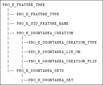
The element tree for the Designated Area feature is documented in the header file ProDesignatedArea.h. The following figure demonstrates the feature element tree structure:
Feature Element Tree for a Designated Area
Image
The following list details special information about the elements in this tree:
•  PRO_E_FEATURE_TYPE—Specifies the feature type, should always have the value PRO_FEAT_DSGNT_AREA.
•  PRO_E_STD_FEATURE_NAME—Specifies the name of the designated area feature.
•  PRO_E_DSGNTAREA_CREATION—Specifies the data used for creation of the designated area. It consists of the following elements:
  PRO_E_DSGNTAREA_CREATION_TYPE—Specifies whether the designated area lies on a solid, a quilt, or on a plane, where the new surface will be constructed from a chain not related to existing surfaces. It can have one of the following values:
  PRO_DSGNTA_CR_SOLID — Specifies that the feature is created on a solid model.
  PRO_DSGNTA_CR_QUILT — Specifies that the feature is created on a selected quilt
  PRO_DSGNTA_CR_AIR — Specifies that the feature is created on a plane from a chain of curves not lying on any model surface
  PRO_E_DSGNTAREA_LIE_ON — Specifies the placement reference of the feature. If the type is PRO_DSGNTA_CR_QUILT, the feature must include the placement quilt. If the type is PRO_DSGNTA_CR_SOLID, it can optionally include a single surface of the solid, which will be the only surface of the solid used in constructing the feature. If you do not specify a single surface, all solid surfaces will be included in the designated area feature references.
  PRO_E_DSGNTAREA_CREATION_FLIP — Specifies the flip option to switch between inside and outside the boundary chains, and can be set to either TRUE or FALSE.
•  PRO_E_DSGNTAREA_SETS—Specifies an array of compound elements of the type PRO_E_DSGNTAREA_SET that contain the designated area boundaries.
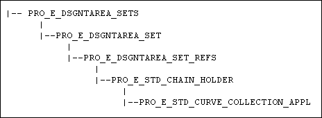
Element Details of PRO_E_DSGNTAREA_SET
PRO_E_DSGNTAREA_SETS
Image
Each PRO_E_DSGNTAREA_SET contains the following element:
PRO_E_DSGNTAREA_SET_REFS — Specifies the set of references to be used for creation of the designated area and consists of the following element:
•  PRO_E_STD_CHAIN_HOLDER — Specifies the set of chains and can consists of one or more of the following element:
  PRO_E_STD_CURVE_COLLECTION_APPL — Specifies the collection of curves to be used as reference. Each curve set must consist of a closed loop. For more information about curve collections, refer to the chapter, User Interface: Curve and Surface Collection.
Accessing Designated Area Properties
The following functions determine the appearance of the designated area by controlling its boundary properties such as the line style and the appearance of the surface.
Functions Introduced:
The function ProDesignatedareaStatusGet() identifies the current status of the geometry of the created designated area. The input value to this function is a quilt from the designated area, or from a data sharing feature referencing the designated area.
The output geometry can have one of the following values:
•  PRO_DSGNTAREA_STATUS_ACTIVE—Specifies that the geometry is active in the indicated model.
•  PRO_DSGNTAREA_STATUS_INACTIVE—Specifies that the geometry is inactive due to geometry features occurring after the designated area feature in the regeneration order.
•  PRO_DSGNTAREA_STATUS_OUT_OF_COPIED_GEOM—Specifies that the parent geometry used from the trimming was cut out from the model.
The function ProDesignatedareaLinestyleGet() returns the line style used for the boundary of the designated area. Use the function ProDesignatedareaLinestyleSet() to set the line style.
The function ProDesignatedareaColorGet() returns the color used for the boundary of the designated area. Use the function ProDesignatedareaColorSet() to set the color.