Consider the following definitions:
|
• |
surface—An ideal geometric representation, that is, an infinite plane. |
|
• |
face—A trimmed surface. A face has one or more contours. |
|
• |
contour—A closed loop on a face. A contour consists of multiple edges. A contour can belong to one face only. |
|
• |
edge—The boundary of a trimmed surface. An edge of a solid is the intersection of two surfaces. The edge belongs to those two surfaces, hence to two contours. An
edge of a datum surface can be either the intersection of two datum surfaces, or the external boundary of the surface. If
the edge is the intersection of two datum surfaces, it will belong to those two surfaces (hence, to two contours). If the
edge is the external boundary of the datum surface, it will belong to that surface alone (hence, to a single contour).
|
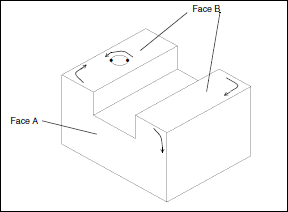
Examples 1 through 5 show some sample parts and list the information about their surfaces, faces, contours, and edges.
Example 1
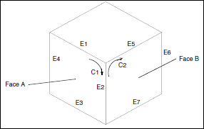
This part has 6 faces.
|
• |
Face A has 1 contour and 4 edges. |
|
• |
Edge E2 is the intersection of faces A and B. |
|
• |
Edge E2 is a component of contours C1 and C2. |
Example 2
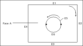
Face A has 2 contours and 6 edges.
Example 3
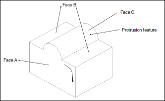
This part was extruded from a rectangular cross section. The feature on the top was added later as an extruded protrusion
in the shape of a semicircle.
|
• |
Face A has 1 contour and 6 edges. |
|
• |
Face B has 2 contours and 8 edges. |
|
• |
Face C has 1 contour and 4 edges. |
Example 4
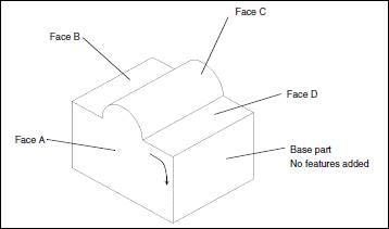
This part was extruded from a cross section identical to Face A. In the Sketcher, the top boundary was sketched with two lines
and an arc. The sketch was then extruded to form the base part, as shown.
|
• |
Face A has 1 contour and 6 edges. |
|
• |
Face B has 1 contour and 4 edges. |
|
• |
Face C has 1 contour and 4 edges. |
|
• |
Face D has 1 contour and 4 edges. |
Example 5
This part was extruded from a rectangular cross section. The slot and hole features were added later.
|
• |
Face A has 1 contour and 8 edges. |
|
• |
Face B has 3 contours and 10 edges. |
